EP1239272A2 - Filtre accordable avec moniteur de longueur d'onde - Google Patents
Filtre accordable avec moniteur de longueur d'onde Download PDFInfo
- Publication number
- EP1239272A2 EP1239272A2 EP02004945A EP02004945A EP1239272A2 EP 1239272 A2 EP1239272 A2 EP 1239272A2 EP 02004945 A EP02004945 A EP 02004945A EP 02004945 A EP02004945 A EP 02004945A EP 1239272 A2 EP1239272 A2 EP 1239272A2
- Authority
- EP
- European Patent Office
- Prior art keywords
- light beam
- wavelength
- tunable filter
- input
- monitor
- Prior art date
- Legal status (The legal status is an assumption and is not a legal conclusion. Google has not performed a legal analysis and makes no representation as to the accuracy of the status listed.)
- Withdrawn
Links
Images


Classifications
-
- G—PHYSICS
- G02—OPTICS
- G02B—OPTICAL ELEMENTS, SYSTEMS OR APPARATUS
- G02B6/00—Light guides; Structural details of arrangements comprising light guides and other optical elements, e.g. couplings
- G02B6/24—Coupling light guides
- G02B6/26—Optical coupling means
- G02B6/28—Optical coupling means having data bus means, i.e. plural waveguides interconnected and providing an inherently bidirectional system by mixing and splitting signals
- G02B6/293—Optical coupling means having data bus means, i.e. plural waveguides interconnected and providing an inherently bidirectional system by mixing and splitting signals with wavelength selective means
- G02B6/29346—Optical coupling means having data bus means, i.e. plural waveguides interconnected and providing an inherently bidirectional system by mixing and splitting signals with wavelength selective means operating by wave or beam interference
- G02B6/29361—Interference filters, e.g. multilayer coatings, thin film filters, dichroic splitters or mirrors based on multilayers, WDM filters
-
- G—PHYSICS
- G01—MEASURING; TESTING
- G01J—MEASUREMENT OF INTENSITY, VELOCITY, SPECTRAL CONTENT, POLARISATION, PHASE OR PULSE CHARACTERISTICS OF INFRARED, VISIBLE OR ULTRAVIOLET LIGHT; COLORIMETRY; RADIATION PYROMETRY
- G01J3/00—Spectrometry; Spectrophotometry; Monochromators; Measuring colours
- G01J3/12—Generating the spectrum; Monochromators
-
- G—PHYSICS
- G01—MEASURING; TESTING
- G01J—MEASUREMENT OF INTENSITY, VELOCITY, SPECTRAL CONTENT, POLARISATION, PHASE OR PULSE CHARACTERISTICS OF INFRARED, VISIBLE OR ULTRAVIOLET LIGHT; COLORIMETRY; RADIATION PYROMETRY
- G01J9/00—Measuring optical phase difference; Determining degree of coherence; Measuring optical wavelength
-
- G—PHYSICS
- G02—OPTICS
- G02B—OPTICAL ELEMENTS, SYSTEMS OR APPARATUS
- G02B6/00—Light guides; Structural details of arrangements comprising light guides and other optical elements, e.g. couplings
- G02B6/24—Coupling light guides
- G02B6/26—Optical coupling means
- G02B6/28—Optical coupling means having data bus means, i.e. plural waveguides interconnected and providing an inherently bidirectional system by mixing and splitting signals
- G02B6/293—Optical coupling means having data bus means, i.e. plural waveguides interconnected and providing an inherently bidirectional system by mixing and splitting signals with wavelength selective means
- G02B6/29379—Optical coupling means having data bus means, i.e. plural waveguides interconnected and providing an inherently bidirectional system by mixing and splitting signals with wavelength selective means characterised by the function or use of the complete device
- G02B6/29395—Optical coupling means having data bus means, i.e. plural waveguides interconnected and providing an inherently bidirectional system by mixing and splitting signals with wavelength selective means characterised by the function or use of the complete device configurable, e.g. tunable or reconfigurable
-
- G—PHYSICS
- G01—MEASURING; TESTING
- G01J—MEASUREMENT OF INTENSITY, VELOCITY, SPECTRAL CONTENT, POLARISATION, PHASE OR PULSE CHARACTERISTICS OF INFRARED, VISIBLE OR ULTRAVIOLET LIGHT; COLORIMETRY; RADIATION PYROMETRY
- G01J3/00—Spectrometry; Spectrophotometry; Monochromators; Measuring colours
- G01J3/12—Generating the spectrum; Monochromators
- G01J2003/1226—Interference filters
- G01J2003/1247—Tuning
-
- G—PHYSICS
- G02—OPTICS
- G02B—OPTICAL ELEMENTS, SYSTEMS OR APPARATUS
- G02B6/00—Light guides; Structural details of arrangements comprising light guides and other optical elements, e.g. couplings
- G02B6/24—Coupling light guides
- G02B6/26—Optical coupling means
- G02B6/28—Optical coupling means having data bus means, i.e. plural waveguides interconnected and providing an inherently bidirectional system by mixing and splitting signals
- G02B6/293—Optical coupling means having data bus means, i.e. plural waveguides interconnected and providing an inherently bidirectional system by mixing and splitting signals with wavelength selective means
- G02B6/29304—Optical coupling means having data bus means, i.e. plural waveguides interconnected and providing an inherently bidirectional system by mixing and splitting signals with wavelength selective means operating by diffraction, e.g. grating
- G02B6/29305—Optical coupling means having data bus means, i.e. plural waveguides interconnected and providing an inherently bidirectional system by mixing and splitting signals with wavelength selective means operating by diffraction, e.g. grating as bulk element, i.e. free space arrangement external to a light guide
- G02B6/2931—Diffractive element operating in reflection
Definitions
- the present invention relates to a tunable filter capable of selectively outputting an input light beam having a predetermined wavelength.
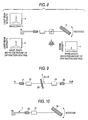
- Fig. 9 shows a conventional tunable filter that can selectively output an input light beam having a predetermined wavelength.
- Numeral 21 is an input side optical fiber.
- An input light beam is input into a bandpass filter 23 via a condensing lens 22.
- An output light beam from the bandpass filter 23 is supplied to an output side optical fiber 25 via an output side condensing lens 24.
- Adielectric film whose thickness is changed in the arrowed direction as shown in FIG.9 is coated on a surface into which the light beam from the bandpass filter 23 is input.
- Thebandpass filter 23 is slidable in the arroweddirection in FIG.9, and can select the wavelength of the to-be-passed light beam by adjusting a thickness of the surface, onto which the incident light beam is irradiated, of the dielectric film.
- Fig. 10 shows another tunable filter that can selectively output an input light beam having a predetermined wavelength.
- Numeral 26 is a two-core optical fiber, and can pass the input light beam and the output light beam.
- a condensing lens 27 is provided commonly to the input light beam and the output light beam, and inputs the light beam in a diffraction grating 28 and outputs the output light beam having the selected wavelength to the output side of the two-core fiber.
- the diffraction grating 28 is rotatable in the arrowed direction of FIG.10, and can select the wavelength of the diffracted light beam by adjusting an angle of the diffraction grating onto which the input light beam is irradiated.
- the wavelength of the to-be-output light beam can be selected by either sliding the bandpass filter or rotating the diffraction grating, but a means for detecting which wavelength of the light beam that is being output is not provided.
- a tunable filter with a wavelength monitor comprising:
- the separator can get a part of a light beam, which is to be monitored, from the reflected light beam of the light beam input from the wavelength selector.
- the wavelength of the light beam to be monitored is the wavelength in vicinity of the wavelength that is selected by the filter.
- the separator can separate a part of a light beam, which is to be monitored, from an output light beam of the wavelength selector by an optical coupler.
- the wavelength of the light beam to be monitored is the wavelength that is selected by the filter.
- the separator can separate a part of a light beam, which is to be monitored, from an output light beam of the wavelength selector by a beam splitter.
- the wavelength of the light beam to be monitored is the wavelength that is selected by the filter.
- the wavelength selector can be constructed as a bandpass filter that can be slid in a direction along which a thickness of a dielectric film is changed.
- the wavelength selector can be constructed as a diffraction grating whose angle to an incident light beam can be adjusted.
- the tunable filter with a wavelength monitor further comprises a reflector for reflecting an output light beam from the wavelength selector, and the reflected light beam from the reflector is input again into the wavelength selector.
- the input light beam is passed through the bandpass filter or the diffraction grating serving as the wavelength selector twice, the bandwidth to be selected can be further narrowed.
- the device can be miniaturized.
- the monitor is constructed by a photodiode, it is possible to monitor the wavelength with a simple structure.
- Fig.1 is a view showing a structure of a first tunable filter with a wavelength monitor.
- Fig.2 is a view showing a structure of a second tunable filter with a wavelength monitor.
- Fig.3 is a view showing a structure of a third tunable filter with a wavelength monitor.
- Fig.4 is a view showing a structure of a fourth tunable filter with a wavelength monitor.
- Fig. 5 is a view showing a structure of a fifth tunable filter with a wavelength monitor.
- Fig.7 is a view illustrating waveforms in operation of the second tunable filter with the wavelength monitor.
- Fig. 8 is a view illustrating waveforms in operation of the fourth tunable filter with the wavelength monitor.
- FIG.9 is a view showing a structure of a tunable filter in the related art.
- FIG.10 is a view showing a structure of another tunable filter in the related art.
- FIG.1 is a view showing a structure of a first tunable filter with a wavelength monitor.
- Numeral 1 is an input side optical fiber.
- An input light beam is input into abandpass filter 3 via an input side condensing lens 2.
- An output light beam from the bandpass filter 3 is supplied to an output side optical fiber 5 via an output side condensing lens 4.
- a dielectric film whose thickness is changed in the arrowed direction in FIG.1 is coated on a surface into which the light beam from the bandpass filter 3 is input.
- the bandpass filter 3 is slidable in the arrowed direction in FIG.1, and can select the wavelength of the to-be-passed light beam by adjusting a thickness of the surface, onto which the incident light beam is irradiated, of the dielectric film.
- Numeral 6 is a wavelength monitor including a photodiode (PD).
- PD photodiode
- a light beam having a wavelength in the vicinity of the wavelength that is selectively transmitted through the bandpass filter 3 to output is reflected by the bandpass filter 3 and then is received by the photodiode (PD).
- the condensing lens must be provided.
- the wavelength of the light beam that is detected by the photodiode (PD) is the wavelength in vicinity of the light beam that is transmitted through the bandpass filter 3. If the relationship between a slide amount of the bandpass filter and the wavelength of the output light beam is measured previously and stored in a table, it is possible to decide which wavelength of the light beam is being output.
- FIG.2 is a view showing a structure of a second tunable filter with a wavelength monitor.
- Numeral 1 is an input side optical fiber.
- the input light beam is input into the bandpass filter 3 via the input side condensing lens 2.
- the output light beam is supplied from the bandpass filter 3 to the output side optical fiber 5 via the output side condensing lens 4.
- the dielectric film whose thickness is changed in the arrowed direction of FIG.2 is coated on the surface into which the light beam from the bandpass filter 3 is input.
- the bandpass filter 3 is slidable in the arrowed direction of FIG.2, and can select the wavelength of the to-be-passed light beam by adjusting the thickness of the surface, onto which the incident light beam is irradiated, of the dielectric film.
- an optical coupler 7 for branching the output light beam from the output side optical fiber 5 is provided in FIG.2.
- the light beam that is branched from the optical coupler 7 by several % is supplied to a monitor port such as the photodiode (PD) in FIG.1 such that the output light beam can be monitored.
- PD photodiode
- the light beam to be monitored has the selected wavelength of the output light beam that is transmitted through the bandpass filter 3.
- the wavelength of the light beam that is detected by the photodiode (PD) is the wavelength of the light beam that is transmitted through the bandpass filter 3. If the relationship between the slide amount of the bandpass filter and the wavelength of the output light beam is measured previously and stored in the table, it is possible to decide which wavelength of the light beam is being output.
- FIG.3 is a view showing a structure of a third tunable filter with a wavelength monitor.
- Numeral 8 is a two-core fiber in which the input side optical fiber and the output side optical fiber are incorporated.
- Numeral 9 is a condensing lens that is common to the input side and the output side, and inputs the input light beam into the bandpass filter 3 and supplies the output light beam from the bandpass filter 3 to the output side optical fiber.
- the dielectric film whose thickness is changed in the arrowed direction of FIG.3 is coated on the surface into which the light beam from the bandpass filter 3 is input.
- the bandpass filter 3 is slidable in the arrowed direction in FIG.3, and can select the wavelength of the to-be-passed light beam by adjusting the thickness of the surface, onto which the incident light beam is irradiated, of the dielectric film.
- the light beam that is transmitted through the bandpass filter 3 is reflected by a mirror 10 and then transmitted through the bandpass filter 3 once again.
- the selectivity of the wavelength (the narrower identification of the bandwidth) can be further enhanced.
- Numeral 6 is a wavelength monitor including the photodiode (PD).
- the light beam having the wavelength in vicinity of the wavelength which is transmitted selectively for the first time and output, is reflected by the bandpass filter 3 and then received by the photodiode (PD).
- the condensing lens must be provided.
- the wavelength of the light beam that is detected by the photodiode (PD) is the wavelength of the light beam that is transmitted through the bandpass filter 3. If the relationship between a variable amount of the bandpass filter and the wavelength of the output light beam is measured previously and stored in the table, it is possible to decide which wavelength of the light beam is being output.
- FIG.4 is a view showing a structure of a fourth tunable filter with a wavelength monitor.
- Numeral 8 is the two-core fiber that contains the input side optical fiber and the output side optical fiber.
- Numeral 9 is the condensing lens that is common to the input side and the output side, and irradiates the input light beam to a diffraction grating 12 via a beam splitter 11 whose branching ratio is variable.
- the diffraction grating 12 is rotatable in the arrowed direction of FIG.4, and can select the wavelength, that is reflected to the beam splitter 11, by adjusting its angle to the input light beam.
- the beam splitter 11 is constructed such that the light beam from the diffraction grating 12 is supplied to the photodiode (PD) by several % and is monitored.
- the wavelength of the light beam that is detected by the photodiode (PD) is the wavelength of the light beam that is diffracted selectively by the diffraction grating 12. If the relationship between a rotation amount of the diffraction grating and the wavelength of the output light beam is measured previously and stored in the table, it is possible to decide which wavelength of the light beam is being output.
- FIG.5 is a view showing a structure of a fifth tunable filter with a wavelength monitor.
- Numeral 8 is a two-core fiber that contains an input side optical fiber and output side optical fiber.
- Numeral 9 is a condensing lens that is common to the input side and the output side, and irradiates the input light beam onto the diffraction grating 12.
- Numeral 13 is a mirror that is rotatable in the arrowed direction of FIG.5.
- the mirror 13 can select the wavelength by adjusting its angle to the input light beam.
- the selectivity of the wavelength can be further enhanced.
- the optical coupler 7 for branching the output light beam from the output side optical fiber is provided in FIG.5.
- the light beam that is branched from the optical coupler 7 by several % is supplied to the monitor port such as the photodiode (PD) in FIG.1 such that the output light beam can be monitored.
- PD photodiode
- the light beam to be monitored has the selected wavelength of the output light beam that is transmitted through the bandpass filter 3.
- the wavelength of the light beam that is detected by the photodiode (PD) is the wavelength of the light beam that is diffracted selectively by the diffraction grating. If the relationship between a rotation amount of the mirror and the wavelength of the output light beam is measured previously and stored in the table, it is possible to decide which wavelength of the light beam is being output.
- FIG.6 is a view illustrating waveforms in operation of the first tunable filter with the wavelength monitor shown in FIG.1.
- a is a view showing the relationship between the wavelength of the input light beam and its light beam intensity.
- “b” is a view showing the relationship between the wavelength (the slide amount of the bandpass filter 3) of the light beam being monitored by the photodiode (PD) and a signal intensity when the bandpass filter 3 is slid.
- c is a view showing the light beam intensity of the output light beam in connection with the slide amount of the bandpass filter 3 when the bandpass filter 3 is slid.
- FIG.7 is a view illustrating waveforms in operation of the second tunable filter with the wavelength monitor.
- a is a view showing the relationship between the wavelength of the input light beam and the light beam intensity.
- “b” is a view showing the wavelength (the slide amount of the bandpass filter 3) of the light beam being monitored by the monitor port and the signal intensity when the bandpass filter 3 is slid.
- c is a view showing the light beam intensity of the output light beam in connection with the slide amount of the bandpass filter 3 when the bandpass filter 3 is slid.
- FIG.8 is a view illustrating waveforms in operation of the fourth tunable filter with the wavelength monitor shown in FIG.4.
- a is a view showing the relationship between the wavelength of the input light beam and the light beam intensity.
- “b” is a view showing the relationship between the wavelength (rotation amount of the diffraction grating 12) of the light beam being monitored by the photodiode (PD) and the signal intensity when the diffraction grating 12 is rotated.
- c is a view showing the light beam intensity of the output light beam in connection with the rotation amount of the diffraction grating 12 when the diffraction grating 12 is rotated.
- wavelength monitoring function is added to the tunable filter, a part of the light beam being transmitted or reflected when the filter is swept can be monitored and thus wavelength information of the input light beam can be obtained from the monitored signal.
- the tunable filter of the present invention can be employed as the tunable filter that is capable of setting automatically the selected wavelength of the filter to the wavelength of the input light beam based on the resultant wavelength information.
- the tunable filter of the present invention can be employed as the simplified wavemeter or the simplified optical spectrum analyzer.
- a tunable filter with a wavelength monitor comprising a wavelength selector, a separator for separating a part of a transmitted light beam or a reflected light beam when a wavelength is swept by the wavelength selector, and a monitor for monitoring a part of a separated light beam. Therefore, it is possible to obtain wavelength information of the light beam source.
- the separator can get a part of a light beam, which is to be monitored, from the reflected light beam of the light beam input from the wavelength selector.
- the wavelength of the light beam to be monitored is the wavelength in vicinity of the wavelength that is selected by the filter.
- the separator can separate a part of a light beam, which is to be monitored, from an output light beam of the wavelength selector by an optical coupler.
- the wavelength of the light beam to be monitored is the wavelength that is selected by the filter.
- the separator can separate a part of a light beam, which is to be monitored, from an output light beam of the wavelength selector by a beam splitter.
- the wavelength of the light beam to be monitored is the wavelength that is selected by the filter.
- the wavelength selector can be constructed as a bandpass filter that can be slid in a direction along which a thickness of a dielectric film is changed.
- the wavelength selector includes a diffraction grating whose angle to an incident light beam can be adjusted.
- a tunable filter with a wavelength monitor further comprises a reflector for reflecting an output light beam from the wavelength selector, and the reflected light beam from the reflector is input again into the wavelength selector.
- the device since a two-core fiber through which an input light beam and an output light beam are passed respectively is employed, the device can be miniaturized.
- the monitor is constructed by a photodiode, it is possible to monitor the wavelength with a simple structure.
Landscapes
- Physics & Mathematics (AREA)
- General Physics & Mathematics (AREA)
- Spectroscopy & Molecular Physics (AREA)
- Optics & Photonics (AREA)
- Mechanical Light Control Or Optical Switches (AREA)
- Spectrometry And Color Measurement (AREA)
- Lasers (AREA)
- Length Measuring Devices By Optical Means (AREA)
- Optical Filters (AREA)
- Diffracting Gratings Or Hologram Optical Elements (AREA)
Applications Claiming Priority (2)
| Application Number | Priority Date | Filing Date | Title |
|---|---|---|---|
| JP2001066689 | 2001-03-09 | ||
| JP2001066689A JP2002267952A (ja) | 2001-03-09 | 2001-03-09 | 波長モニタ付チューナブルフィルタ |
Publications (2)
| Publication Number | Publication Date |
|---|---|
| EP1239272A2 true EP1239272A2 (fr) | 2002-09-11 |
| EP1239272A3 EP1239272A3 (fr) | 2004-03-24 |
Family
ID=18925149
Family Applications (1)
| Application Number | Title | Priority Date | Filing Date |
|---|---|---|---|
| EP02004945A Withdrawn EP1239272A3 (fr) | 2001-03-09 | 2002-03-05 | Filtre accordable avec moniteur de longueur d'onde |
Country Status (4)
| Country | Link |
|---|---|
| US (1) | US20030067601A1 (fr) |
| EP (1) | EP1239272A3 (fr) |
| JP (1) | JP2002267952A (fr) |
| CA (1) | CA2372797A1 (fr) |
Cited By (1)
| Publication number | Priority date | Publication date | Assignee | Title |
|---|---|---|---|---|
| US10267709B2 (en) | 2012-05-07 | 2019-04-23 | Nederlandse Organisatie Voor Toegepast-Natuurwetenschappelijk Onderzoek Tno | Optical sensor interrogation system a method of manufacturing the optical sensor interrogation system |
Families Citing this family (9)
| Publication number | Priority date | Publication date | Assignee | Title |
|---|---|---|---|---|
| JP2002277757A (ja) * | 2001-03-16 | 2002-09-25 | Ando Electric Co Ltd | チューナブルフィルタ |
| US7209230B2 (en) | 2004-06-18 | 2007-04-24 | Luckoff Display Corporation | Hand-held spectra-reflectometer |
| US7233394B2 (en) | 2005-06-20 | 2007-06-19 | Luckoff Display Corporation | Compact spectrometer |
| US7576856B2 (en) * | 2006-01-11 | 2009-08-18 | Baker Hughes Incorporated | Method and apparatus for estimating a property of a fluid downhole |
| US7595876B2 (en) * | 2006-01-11 | 2009-09-29 | Baker Hughes Incorporated | Method and apparatus for estimating a property of a fluid downhole |
| US7897912B2 (en) * | 2006-05-25 | 2011-03-01 | Photo Research, Inc. | Spectral and luminance measuring device employing array and single-channel detectors in combination |
| JP2008159718A (ja) * | 2006-12-21 | 2008-07-10 | Sharp Corp | マルチチップモジュールおよびその製造方法、並びにマルチチップモジュールの搭載構造およびその製造方法 |
| JP2012008116A (ja) * | 2010-05-26 | 2012-01-12 | Sumitomo Electric Ind Ltd | 分光器およびそれを用いたイメージングシステム |
| JP2025179652A (ja) * | 2024-05-28 | 2025-12-10 | 国立大学法人東北大学 | 分光分析装置及び分光分析方法 |
Family Cites Families (4)
| Publication number | Priority date | Publication date | Assignee | Title |
|---|---|---|---|---|
| US5230005A (en) * | 1991-11-05 | 1993-07-20 | The United States Of America As Represented By The Secretary Of The Navy | Electronic tuning of a broadband laser |
| GB2269230A (en) * | 1992-07-31 | 1994-02-02 | Sinar Agritec Ltd | Measuring light wavelength. |
| JPH11242116A (ja) * | 1998-02-25 | 1999-09-07 | Nec Eng Ltd | 波長可変光フィルタ及びこれを組合わせた光増幅器 |
| JPH11351970A (ja) * | 1998-06-10 | 1999-12-24 | Fujitsu Ltd | 波長検出デバイス |
-
2001
- 2001-03-09 JP JP2001066689A patent/JP2002267952A/ja not_active Withdrawn
-
2002
- 2002-02-22 CA CA002372797A patent/CA2372797A1/fr not_active Abandoned
- 2002-03-05 EP EP02004945A patent/EP1239272A3/fr not_active Withdrawn
- 2002-03-07 US US10/092,917 patent/US20030067601A1/en not_active Abandoned
Cited By (2)
| Publication number | Priority date | Publication date | Assignee | Title |
|---|---|---|---|---|
| US10267709B2 (en) | 2012-05-07 | 2019-04-23 | Nederlandse Organisatie Voor Toegepast-Natuurwetenschappelijk Onderzoek Tno | Optical sensor interrogation system a method of manufacturing the optical sensor interrogation system |
| EP2847548B1 (fr) * | 2012-05-07 | 2019-10-23 | Nederlandse Organisatie voor toegepast- natuurwetenschappelijk onderzoek TNO | Système d'interrogation de capteur optique, procédé de fabrication du système d'interrogation de capteur optique |
Also Published As
| Publication number | Publication date |
|---|---|
| CA2372797A1 (fr) | 2002-09-09 |
| US20030067601A1 (en) | 2003-04-10 |
| EP1239272A3 (fr) | 2004-03-24 |
| JP2002267952A (ja) | 2002-09-18 |
Similar Documents
| Publication | Publication Date | Title |
|---|---|---|
| US5623342A (en) | Raman microscope | |
| CN109564157B (zh) | 用于从宽带源产生多通道可调谐照明的系统及方法 | |
| US5747813A (en) | Broadband microspectro-reflectometer | |
| EP1320731B1 (fr) | Dispositifs optiques comprenant une unite de dispersion a reglage de longueur d'onde equipee d'un reseau de diffraction dispersif en volume | |
| JP3322712B2 (ja) | 光チューナの起動方法及び光チューナ | |
| US6246818B1 (en) | Tunable optical filter | |
| US7221452B2 (en) | Tunable optical filter, optical apparatus for use therewith and method utilizing same | |
| US7864423B2 (en) | Spectrally adjustable filter | |
| EP3588025B1 (fr) | Spectromètre à photodiode unique haute résolution à l'aide d'un filtre optique à bande étroite | |
| EP1239272A2 (fr) | Filtre accordable avec moniteur de longueur d'onde | |
| RU2180468C1 (ru) | Мультиплексор со спектральным разделением с упорядоченной волноводной решеткой, снабженный настроечными волноводами, и устройство для настройки такого мультиплексора | |
| US20020080367A1 (en) | Wavelength measuring apparatus and wavelength tunable light source device with built-in wavelength measuring apparatus | |
| WO2003050488A1 (fr) | Appareils de surveillance de puissance spectrale optique utilisant des systemes de detection a multiplexage en frequence | |
| US6177992B1 (en) | Low insertion loss optical monochromator | |
| US7327453B2 (en) | Post dispersion spatially filtered Raman spectrometer | |
| US7041959B1 (en) | System and method for monitoring the performance of dense wavelength division multiplexing optical communications systems | |
| US6836349B2 (en) | Optical performance monitoring device | |
| US20040120721A1 (en) | Wavelength stabilizing control device and method thereof | |
| JP4916407B2 (ja) | 光伝送試験装置 | |
| JPH08297088A (ja) | 分光光度計 | |
| US20020081065A1 (en) | Fabry-perot etalon, wavelength measuring apparatus, and wavelength tunable light source device with built-in wavelength measuring apparatus | |
| US6864980B2 (en) | Linear filter based wavelength locking optical sub-assembly and associated methods | |
| GB2259135A (en) | Colour analysis | |
| US20110129216A1 (en) | Tunable optical filters | |
| TW200411148A (en) | Method and device for wavelength locking and spectrum monitoring |
Legal Events
| Date | Code | Title | Description |
|---|---|---|---|
| PUAI | Public reference made under article 153(3) epc to a published international application that has entered the european phase |
Free format text: ORIGINAL CODE: 0009012 |
|
| AK | Designated contracting states |
Kind code of ref document: A2 Designated state(s): AT BE CH CY DE DK ES FI FR GB GR IE IT LI LU MC NL PT SE TR |
|
| AX | Request for extension of the european patent |
Free format text: AL;LT;LV;MK;RO;SI |
|
| PUAL | Search report despatched |
Free format text: ORIGINAL CODE: 0009013 |
|
| AK | Designated contracting states |
Kind code of ref document: A3 Designated state(s): AT BE CH CY DE DK ES FI FR GB GR IE IT LI LU MC NL PT SE TR |
|
| AX | Request for extension of the european patent |
Extension state: AL LT LV MK RO SI |
|
| RIC1 | Information provided on ipc code assigned before grant |
Ipc: 7G 01J 3/26 B Ipc: 7G 01J 9/00 A |
|
| AKX | Designation fees paid | ||
| REG | Reference to a national code |
Ref country code: DE Ref legal event code: 8566 |
|
| STAA | Information on the status of an ep patent application or granted ep patent |
Free format text: STATUS: THE APPLICATION IS DEEMED TO BE WITHDRAWN |
|
| 18D | Application deemed to be withdrawn |
Effective date: 20041001 |