EP1239493A2 - Dispositif électronique et câble de connexion pour dispositif électronique - Google Patents
Dispositif électronique et câble de connexion pour dispositif électronique Download PDFInfo
- Publication number
- EP1239493A2 EP1239493A2 EP02251465A EP02251465A EP1239493A2 EP 1239493 A2 EP1239493 A2 EP 1239493A2 EP 02251465 A EP02251465 A EP 02251465A EP 02251465 A EP02251465 A EP 02251465A EP 1239493 A2 EP1239493 A2 EP 1239493A2
- Authority
- EP
- European Patent Office
- Prior art keywords
- layer
- signal lines
- disposed
- speed signal
- lines
- Prior art date
- Legal status (The legal status is an assumption and is not a legal conclusion. Google has not performed a legal analysis and makes no representation as to the accuracy of the status listed.)
- Withdrawn
Links
- 230000005540 biological transmission Effects 0.000 claims abstract description 50
- 230000002093 peripheral effect Effects 0.000 claims description 12
- 239000010410 layer Substances 0.000 description 83
- 238000012546 transfer Methods 0.000 description 16
- 238000003780 insertion Methods 0.000 description 13
- 230000037431 insertion Effects 0.000 description 13
- 229910000859 α-Fe Inorganic materials 0.000 description 7
- 239000002184 metal Substances 0.000 description 5
- 238000012545 processing Methods 0.000 description 5
- NIXOWILDQLNWCW-UHFFFAOYSA-N acrylic acid group Chemical group C(C=C)(=O)O NIXOWILDQLNWCW-UHFFFAOYSA-N 0.000 description 3
- 238000010276 construction Methods 0.000 description 3
- 239000000835 fiber Substances 0.000 description 3
- 230000006872 improvement Effects 0.000 description 3
- 230000008878 coupling Effects 0.000 description 2
- 238000010168 coupling process Methods 0.000 description 2
- 238000005859 coupling reaction Methods 0.000 description 2
- 230000000694 effects Effects 0.000 description 2
- 239000000463 material Substances 0.000 description 2
- 230000009467 reduction Effects 0.000 description 2
- 239000011347 resin Substances 0.000 description 2
- 229920005989 resin Polymers 0.000 description 2
- 238000007796 conventional method Methods 0.000 description 1
- 238000001816 cooling Methods 0.000 description 1
- 238000013016 damping Methods 0.000 description 1
- 238000011161 development Methods 0.000 description 1
- 230000006870 function Effects 0.000 description 1
- 239000011810 insulating material Substances 0.000 description 1
- 238000000034 method Methods 0.000 description 1
- 238000012986 modification Methods 0.000 description 1
- 230000004048 modification Effects 0.000 description 1
- 230000003287 optical effect Effects 0.000 description 1
- 238000007639 printing Methods 0.000 description 1
- 230000004044 response Effects 0.000 description 1
- 239000002356 single layer Substances 0.000 description 1
- 125000006850 spacer group Chemical group 0.000 description 1
- 238000009941 weaving Methods 0.000 description 1
Images
Classifications
-
- H—ELECTRICITY
- H01—ELECTRIC ELEMENTS
- H01B—CABLES; CONDUCTORS; INSULATORS; SELECTION OF MATERIALS FOR THEIR CONDUCTIVE, INSULATING OR DIELECTRIC PROPERTIES
- H01B11/00—Communication cables or conductors
- H01B11/02—Cables with twisted pairs or quads
- H01B11/06—Cables with twisted pairs or quads with means for reducing effects of electromagnetic or electrostatic disturbances, e.g. screens
Definitions
- the present invention relates to an electronic device connection cable having a plurality of high-speed signal lines, a plurality of ground lines, and a plurality of low-speed signal lines.
- a video game device, an entertainment device, and similar electronic devices are practically used.
- One of those electronic devices includes a main unit including a central processing unit (CPU) and other electronic components disposed in a case.
- the electronic device has a controller connected to the main unit and controlled by the controller.
- Such an electronic device generally uses a storage device such as a flash memory.
- a storage device is generally provided in the form of a card that can be attached to the main unit of the electronic device.
- Advanced electronic devices deal with a large amount of information and need a high-capacity storage device such as a hard disk drive (HDD).
- HDD hard disk drive
- One technique to meet the above requirement is to connect a peripheral device serving as an external high-capacity storage device to the electronic device and use it instead of the card-type storage device having only limited storage capacity.
- a peripheral device To connect such a peripheral device to a main unit of an electronic device, it is known in the art to use a cable and an interface according to a proper standard such as the ATA (AT Attachment) standard established by the American National Standards Institute (ANSI) or the SCSI (Small Computer System Interface) standard.
- ATA AT Attachment
- SCSI Small Computer System Interface
- Another standard for the interface between a main unit of an electronic device and a peripheral device is the UltraATA/66 (UltraDMA/66) standard.
- the interface according to this standard allows a connection at a rather high speed and at low cost.
- a connector for connecting electronic devices with each other includes 40 pins for data signal lines according to the ATA standard, and a transmission part (cable) includes 40 data signal lines connected to the respective pins and 40 ground lines that are disposed in correspondence with the respective signal lines so as to improve signal quality.
- the 40 ground lines and 40 data signal lines are alternately disposed in a single flat layer. That is, the cable according to this standard includes a total of 80 signal lines that are all disposed in the single flat layer.
- the transmission part has a flat structure in which all signal lines are disposed parallel to one another in the same single layer, the outward appearance of the transmission part may not be good, and it may not be easy to bend the transmission part when the transmission part is connected to an electronic device. Similar problems may also occur in any flat-type cable according to standards other than UltraATA/66.
- each pair of lines is formed by twisting together one data signal line and one ground line, and a plurality of twisted pairs are combined together into a bundle that is circular in cross section.
- this type of transmission part some portions of data signal lines are brought into proximity with one another. This may cause crosstalk noise to be generated among data signal lines, and thus this type of transmission part is not used in practical applications in which it is needed to transmit data signals at a high speed.
- twisting lines makes it difficult to bend the transmission part and thus it is not easy to handle it.
- an electronic device connection cable comprising a transmission part including a plurality of high-speed signal lines and a plurality of ground lines; and a tube-shaped sheath in which the transmission part is disposed such that the outer surface of the transmission part is covered with the sheath; wherein the high-speed signal lines and the ground lines are disposed such that no interference occurs among signals traveling through the high-speed signal lines.
- the high-speed signal line refers to a data signal line or the like for transferring data at a high speed in synchronization with a clock frequency to read or write the data.
- Interference between signals refers to a state in which a signal traveling through a signal line exerts so great influence on a signal traveling through another signal line that the signal is not transmitted correctly.
- the high-speed signal lines and the ground lines are arranged so that no interference occurs among signals transmitted through the high-speed signal lines and noise due to crosstalk among the high-speed signal lines is suppressed to a very low level thereby ensuring that data is transmitted between electronic devices in a highly reliable fashion.
- the electronic device connection cable can be easily bent in any desired direction, because the electronic device connection cable is disposed within a sheath having the shape of a tube. This makes it possible to easily connect the electronic device connection cable to a device.
- the "tube" shape refers to a shape that is circular, elliptic, or a polygonal in cross section. Because the transmission part includes no twisted pair of lines, the transmission part is soft enough to easily bend. This makes it possible to easily handle the transmission part.
- the transmission part includes a plurality of high-speed signal lines, a plurality of ground lines, and a plurality of low-speed signal lines
- the sheath is formed into the shape of a tube within which the transmission part is disposed such that the surface of the transmission part is covered with the sheath, wherein high-speed signal lines and ground lines are alternately disposed in a first layer located at an outermost position in the transmission part.
- the "low-speed signal line” refers to a data signal line used to transfer data, such as a signal for controlling an access indicator to indicate whether an electronic device is being accessed by another electronic device, at a rather low transfer rate.
- any two high-speed signal lines are not disposed at directly adjacent locations, and thus noise due to crosstalk among the high-speed signal lines is suppressed to a very low level thereby ensuring that data is transferred between electronic devices in a highly reliable fashion. Furthermore, because the high-speed signal lines are disposed in the first layer disposed at the outermost locations where coupling among high-speed data signal lines is lower than in any other layer, noise due to crosstalk can be suppressed to a lower level than can be achieved when the high-speed signal lines are disposed in an inner layer.
- the sheath is formed so as to have the shape of a tube having no flat surface portion, the transmission part can be easily bent in any desired direction. This results in an improvement in ease of handling.
- the transmission part includes, in addition to the first. layer described above, a second layer radially inwardly adjacent to the first layer and a third layer radially inwardly adjacent to the second layer, wherein in a case where the total number of high-speed signal lines included in the transmission part is greater than a number of high-speed signal lines that can be disposed in the first layer, high-speed signal lines that cannot be disposed in the first layer are disposed in the third layer such that high-speed signal lines and ground lines are located alternately.
- the third layer and the first layer are not disposed at directly adjacent locations and because, also in the third layer, high-speed signal lines and ground lines are alternately disposed, any two high-speed signal lines are not disposed at directly adjacent locations and thus noise due to crosstalk among the high-speed signal lines is suppressed to a very low level. Furthermore, because some of the high-speed signal lines are disposed in the third layer, the number of signal lines disposed in the first layer can be reduced, and thus the diameter of the transmission part can be reduced. This makes it possible to bend the transmission part more easily. Thus, the transmission part can be handled more easily.
- the high-speed signal lines include high-speed data signal lines and clock lines; and, in the first layer at the outermost location in the transmission part, high-speed data signal lines and ground lines are alternately disposed, wherein in a case in which there are a greater number of high-speed data signal lines than can be disposed in the first layer, high-speed data signal lines that cannot be disposed in the first layer are disposed in the third layer such that high-speed data signal lines and ground lines are alternately disposed.
- crosstalk noise among the high-speed data signal lines is suppressed to a very low level when data is transferred through the high-speed data signal lines at a high transfer rate. This ensures high reliability in transferring of data.
- the transmission part includes 18 high-speed signal lines, 20 ground lines, and 22 low-speed signal lines.
- the ground lines are used to suppress crosstalk noise among the high-speed signal lines. Therefore, it is not needed to dispose a ground line between low-speed signal lines, because no significant crosstalk noise occurs among low-speed signal lines.
- this structure needs only 20 ground lines disposed alternately with the 18 high-speed signal lines.
- the high-speed signal lines include 16 high-speed data signal lines and 2 clock lines.
- the high-speed signal lines include 16 high-speed data signal lines and 2 clock lines.
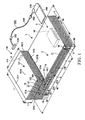
- Fig. 1 is a perspective view of an electronic device according to the embodiment of the present invention.
- This electronic device includes an entertainment device 1 that is a main unit of the electronic device, a hard disk drive (HDD) 100 that is a peripheral unit of the electronic device, and an electronic device connection cable 200 connecting the entertainment device 1 and the hard disk drive 100 to each other.
- an entertainment device 1 that is a main unit of the electronic device
- a hard disk drive (HDD) 100 that is a peripheral unit of the electronic device
- an electronic device connection cable 200 connecting the entertainment device 1 and the hard disk drive 100 to each other.
- the entertainment device 1 reads a game program stored on an optical disk or the like and executes it in accordance with a command issued by a user (game player).
- execution of a game program refers to an operation of controlling progress of a game while controlling an image and a voice/sound.
- the main unit 2 includes a disk drive 11, a power supply unit (not shown), a mother board (not shown), and an input/output signal control board (not shown).
- the mother board includes a control system including a central processing unit (CPU) and peripheral devices thereof, a graphic system including an image processing unit for drawing an image, and a sound system including an audio processing unit for generating a musical sound or a sound effect.
- the case 3 includes a center chassis 4 on which the main unit 2 is constructed, an upper case 5, and a lower case 6, wherein the center chassis on which the main unit 2 is constructed is disposed between the upper case 5 and the lower case 6.
- the case 3 has a rectangular shape when viewed from above and a shape similar to a character of "L" when viewed from the front side.
- the disk drive 11 is disposed in the upper case 5, on a front and right side thereof (as viewed from front).
- the disk drive 11 is used to drive a storage medium such as a CD-ROM or a DVD-ROM on which an application program such as a video game program is stored.
- a front end portion of a disk tray 11B of the disk drive 11 is exposed at the front side of the case 3.
- a power switch 16 serving as control means and a tray switch 17 for controlling the operation of moving out and back the disk tray 11B from/into the upper case 5 are disposed on the front panel.
- Each slot unit 18 is disposed in the upper case 5 on the left side thereof (as viewed from front) such that slots of the respective slot units 18 are exposed via the front panel.
- Each slot unit 18 includes a memory card insertion part 61 disposed at an upper location and a controller connection part 62 disposed at a lower location.
- Each memory card insertion part 61 has an insertion hole 61A in the form of a thin rectangle extending in a horizontal direction.
- a shutter 61B is disposed on each memory card insertion part 61 so as to protect connection terminals disposed inside the memory card insertion part 61.
- Each controller connection part 62 provides an input/output terminal for inputting/outputting a signal.
- a connection terminal disposed at an end of a controller cable (not shown) extending from a controller (not shown) serving as a control device is connected to either one of controller connection parts 62.
- Each controller connection part 62 has an insertion hole 62A in the form of a thin rectangle extending in a horizontal direction, wherein lower corners are rounded while upper corners are not rounded. Rounding the lower corners of each insertion hole 62A prevents the connection terminals of the controller from being connected in an upside-down fashion by mistake.
- the insertion hole 62A has a shape different from the shape of the insertion hole 61A of the memory card insertion part 61 so that an external auxiliary storage device cannot be inserted into the wrong insertion hole 62A by mistake.
- the provision of the two controller connection parts 62 allows two controllers to be connected to the entertainment device 1 thereby allowing two players to enjoy a fighting/competing game or the like.
- the result of an operation performed in accordance with a command issued from a controller connected to each controller connection part 62 is stored in an external auxiliary storage device inserted in the memory card insertion part 61 disposed above the controller connection part 62.
- a PC card slot unit 70 is disposed in the upper case 5 at a rear and left (right when viewed from front) side such that a slot of the PC card slot unit 70 is exposed via a rear panel.
- the PC card slot unit 70 is electrically connected to the mother board of the main unit 2.
- a PC card serving as a card-type peripheral unit according to the PCMCIA (Personal Computer Memory Card International Association) standard or the JEIDA (Japanese Electronic Industry Development Association) standard can be inserted into the PC card slot unit 70.
- the PC card is electrically connected to the main unit 2.
- the PC card may have various functions.
- the PC card may be capable of recognizing a signal according to the ATA standard, or may be capable of recognizing a LAN signal that allows a connection between computers.
- the data transfer terminals 19 are compliant with the IEEE (Institute of Electrical and Electronic Engineers)-1394 standard.
- An end of a cable, the other end of which is connected to a device such as a digital cameral or a video deck, can be connected to the data transmission terminals 19 so that data such as video/audio data can be transferred from the digital camera or the video deck to the entertainment device 1.
- the two external device connection terminals 20 are compliant with the USB (Universal Serial Bus) standard.
- Various types of devices can be connected to either one of external device connection terminals 20.
- examples of devices that can be connected to the external device connection terminals 20 include an input device such as a keyboard, a pointing device such as a mouse, a printing device such as a printer, and an external storage device using a magneto-optical disk, a magnetic medium, or the like.
- An opening 6A in the form of a slit extending in a longitudinal direction of the lower case 6 is formed in the front panel of the lower case 6 so that cooling air is supplied into the inside of the entertainment device I via the opening 6A.
- the entertainment device 1 is placed such that the lower surface with a greatest area of the lower case 6 faces toward a plane on the entertainment device 1 is placed.
- vibration isolator 6B made of rubber are. disposed at proper locations on the lower surface of the lower case 6.
- a peripheral unit such as a hard disk drive 100 is placed on the upper surface of the upper case 5 of the entertainment device 1, as shown in Fig. 1.
- the hard disk drive 100 includes a case 101 having the general shape of a box and a main part 102 disposed inside the case 101.
- the main part 102 of the hard disk drive includes, in the inside thereof, a circuit board (not shown) for controlling an operation of the hard disk drive and an operation of accessing to a peripheral device.
- the circuit board includes a male connector 111 having 40 pins according to the ATA standard.
- the case 101 includes a first outer plate 101A and a second outer plate 101B, both having a flat rectangular shape and located at opposite positions.
- the case 101 further includes a third outer plate 101C, a fourth outer plate 101D, a fifth outer plate 101E, and a six outer plate 101F wherein edges portions of the respective first and second outer plates 101A and 101B are connected via the third, fourth, fifth, and sixth outer plates 101C, 101D, 101E, and 101F.
- the outer plates 101A to 101F define an outer surface of the case 101. These outer plates 101A to 101F are firmly connected to one another with screws (not shown).
- the first outer plate 101A of the hard disk drive 100 becomes parallel with the upper surface of the upper case 5 of the entertainment device 1.
- the first outer plate 101A has a depth L1 equal to the depth M1 of the upper case 5 and has a front width L2 smaller than the with M2 of the upper case 5.
- the depth L1 of the first outer plate 101A is greater than the width L2.
- the second outer plate 101B located opposite the first outer plate 101A serves as a bottom plate that directly faces a plane (the upper surface of the upper case 5 in the example shown in Fig. 1) on which the hard disk drive 100 is placed.
- the second outer plate 101B has a flat rectangular shape with a depth equal to L1 and a width equal to L2.
- Vibration-isolating protrusions are formed at four comers on the lower surface of the second outer plate 101B.
- the vibration-isolating protrusions are constructed into the shape of a thin flat plate using a material such as rubber having the capability of damping vibrations, and fitted into recesses (not shown) formed on the second outer plate 101B.
- the third to sixth outer plates 101C to 101F are disposed such that they extends in a direction perpendicular to both the first outer plate 101A and the second outer plate 101B.
- the third outer plate 101C serves as a front panel of the case 101, wherein the third outer plate has a width equal to L3 and a length equal to L2.
- the length L2 is set to be greater than the width L3.
- an access indicator 104 for indicating whether the hard disk drive 100 is accessed by the central processing unit of the entertainment device 1 and a power indicator 105 for indicating whether the power is on or off are disposed at locations close to each other.
- the access indicator 104 includes a mark 104A and a lamp 104B.
- the mark 104A are formed on the surface 10 and the lamp unit 104B is disposed in a hole 10A.
- the lamp unit 104B includes a transparent acrylic member 104B1 embedded in the hole 10A and a lamp such as a light emitting diode disposed inside the case 101 such that the transparent acrylic member 104B1 is illuminated with light emitted from the lamp.
- the power indicator 105 includes a mark 105A and a lamp unit 105B.
- the mark 105A is formed on the surface 10, and the lamp unit 105B is disposed in a hole 10A.
- the lamp unit 105B includes a transparent acrylic member and a lamp.
- the fifth outer plate 101E extends in a direction perpendicular to the fourth outer plate 101D and parallel with the third outer plate 101C.
- the fifth outer plate 101E has a width equal to L3 and a length equal to L2.
- a power switch and a power terminal via which DC power is supplied from an AC adapter are disposed on the fifth outer plate 101E.
- the male connector 111 described above is exposed via the fifth outer plate 101E.
- the sixth outer plate 10 IF extends in a direction parallel with the fourth outer plate 101D and perpendicular to the outer plates 101A, 101B, 101C, and 101E.
- the sixth outer plate 101F has a width equal to L3 and a length equal to L1.
- the electronic device connection cable 200 includes a main part 210 having a circular shape in cross section, a first female connector 220 disposed on an end of the main part 210 of the cable, and a second female connector 230 disposed on the other end of the main unit 210 of the cable.
- a ferrite core 250 is disposed on the main part 210 of the cable.
- a ferrite core 260 is disposed on the main part 210 of the cable, near the second female connector 230.
- Those ferrite cores 250 and 260 serve as noise filters.
- the second female connector 230 is connected to a PC card 240.
- the first female connector 220 has 40 pins. These pins are compliant with the UltraATA/66 standard so that the first female connector 220 can be connected with the male connector 111 of the hard disk drive 100.
- the second female connector 230 connectable to a PC card 240 has a shape, in cross section, similar to a character "L".
- the axial direction of the main part 210 of the cable is perpendicular to a direction in which the PC card 240 connected with the second female connector 230 is inserted into the entertainment device 1. This makes it possible to easily connect the hard disk drive 100 to the entertainment device 1 without causing the main part 210 of the cable to have undesirable slack.
- the PC card 240 capable of recognizing signals according to the UltraATA/66 standard is inserted into the PC card slot unit 70 when it is used.
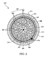
- Fig. 2 is a cross-sectional view of the main part 210 of the cable.
- the main part 210 of the cable is circular in cross section and includes a transmission part 211 and a tube-shaped sheath 212, wherein the surface of the transmission part 211 is covered with the sheath 212.
- the transmission part 211 includes an interleaving fiber core 311 located at the center of the transmission part 211, a bundle 300 of 60 signal lines that are substantially equal in diameter to each other and that are uniformly disposed around the interleaving fiber core 311, a tape 312 disposed around the bundle 300 of signal lines, a woven metal shield 313 disposed outside the tape 312, and a drain wire 314 serving as a ground wire disposed between the tape and the woven metal shield 313.
- the sheath 212 described above is made of a resin. With the resin sheath 212, the outer surface of the woven metal shield 313 is covered.
- the bundle 300 of signal lines includes high-speed signal lines 301 including 16 high-speed data signal lines 302 (denoted by “H” in circles in Fig. 2) and 2 clock lines 303 (denoted by “C” in circles in Fig. 2), 22 low-speed signal lines 304 (denoted by “L” in circles in Fig. 2), and 20 ground lines 305 (denoted by "G” in circles in Fig. 2).
- Each of the signal lines 302 to 305 includes a conductive wire located at the center thereof and covered with an insulating material.
- the woven metal shield 313 is produced by weaving thin conductive wires into the form of a mesh.
- the bundle 300 of signal lines is covered with the woven metal shield 313 to prevent generation of noise.
- the main part 210 of the cable can be regarded as having a structure obtained by removing 20 ground lines from the transmission part including 80 signal lines according to the ATA standard and combining remaining 60 lines 302 to 305 including 20 ground lines 305 and 40 data signal lines 302 to 304 into a bundle.
- the 40 signal lines are connected to the respective 40 ATA-compliant pins of the respective female connectors 220 and 230. That is, the female connectors 220 and 230 located at the respective ends includes pins corresponding to the 40 data signal lines 302 to 304.
- the 16 high-speed data signal lines 302 are used to parallely transfer respective bits of 16-bit data in synchronization with a clock frequency that will be described later. This allows data to be transmitted at a higher rate than can be by serial transmission.
- the two clock lines 303 are used to transfer a clock signal (clock frequency) generated by a clock generator disposed on the mother board of the entertainment device 1.
- the 22 low-speed signal lines 304 are used to transfer data, such as a signal for controlling the access indicator 104 to indicate whether the hard disk drive 100 is being accessed, at a rather low transmission rate between the entertainment device 1 and the hard disk drive 100.
- signal lines 302 to 305 are disposed into a bundle 300 so as to have the overall shape of a circle in cross section.
- the respective signal lines 302 to 305 are disposed at substantially symmetrical locations in cross section.
- the bundle 300 of signal lines has a multilayer structure in which the signal lines 302 to 305 are disposed.
- signal lines are annularly disposed.
- signal lines are disposed in respective layers such that each layer extends along a circumference.
- the respective layers extend along corresponding circumferences of concentric circles.
- the bundle 300 of signal lines includes a first layer 361 at an outermost location in which 24 signal lines are disposed, a second layer 362 which is radially inwardly adjacent to the first layer 361 and in which 18 signal lines are disposed, a third layer 363 which is radially inwardly adjacent to the second layer 362 and in which 12 signal lines are disposed, and a fourth layer 364 which is radially inwardly adjacent to the third layer 363 and in which six signal lines are disposed.
- the first layer 361 includes a total of 24 signal lines including 12 high-speed data signal lines 302 and 12 ground lines 305, which are alternately disposed. More specifically, in the first layer 361, a high-speed data signal line 302 is disposed at the top in Fig. 2, and a ground line 305, a high-speed data signal line 302, a ground line 305, a high-speed data signal line 302 and so on are disposed into a clockwise direction from the high-speed signal line 302 at the top.
- the second layer 362 includes a total of 18 signal lines including 16 low-speed signal lines 304 and two ground lines 305, which are alternately disposed. More specifically, a low-speed signal line 304 is disposed inwardly adjacent to the high-speed data signal line 302 at the top in Fig. 2, and four low-speed signal lines 304, a ground line 305, four low-speed signal lines 304, a ground line 305, and seven low-speed signal lines are disposed in the clockwise direction from the low-speed signal line 304 at the top.
- the third layer 363 includes a total of 12 signal lines including high-speed signal lines 301 including four high-speed data signal line 302 and two clock lines 303 and six ground lines 305, which are alternately disposed. More specifically, in the third layer 363, a high-speed data signal line 302 is disposed radially inwardly adjacent to the low-speed signal line 304 that is disposed inwardly adjacent to the high-speed data signal line 302 at the top in Fig.
- a ground line 305, a high-speed data signal line 302, a ground line 305, a clock line 303, a ground line 305, a high-speed data signal line 302, a ground line 305, a high-speed data signal line 302, a ground line 305, a clock line 303, and a ground line 305 are disposed in the clockwise direction from the high-speed data signal line 302 at the top.
- the fourth layer 364 includes a total of six low-speed signal lines 304 disposed around the core 311.
- the present invention has been described above with reference to preferred embodiments, the invention is not limited to those embodiments. Various modifications and improvements are possible without departing from the spirit and scope of the present invention.
- two ferrite cores 250 and 260 are used in the embodiments described above, an arbitrary number of ferrite cores may be used.
- the ferrite cores are not necessarily needed if noise can be suppressed to a sufficiently low level without using the ferrite cores.
- the drain wire 314 used in the embodiments described above may be removed if similar effects can be achieved using other means such as the ground lines 305.
- the interleaving core 311 made of fiber and the tape 312 made of paper are employed. Alternatively, they may be formed of different materials.
- 12 high-speed data signal lines 302 and 12 ground lines 305 are alternately disposed in the first layer 361.
- 18 high-speed signal lines 301 and 18 ground lines 305 may be alternately disposed.
- the number of signal lines disposed in the first layer 361 is not limited to a particular value but may be set to an arbitrary value taking into account the size of the main part 210 of the cable and noise that is generated, as long as high-speed signal lines 301 and ground lines 305 are alternately disposed.
- the clock lines 303 are disposed in the third layer 362.
- the clock lines 303 may be disposed in the first layer 361.
- two ground lines 305 are disposed at particular locations in the second layer 362. Instead, they may be located at other locations in the second layer 362 or in the fourth layer 364.
- the locations at which the high-speed signal lines 301 and the ground line 305 are disposed in the first layer 361 and the third layer 363 are not limited to those employed in the embodiments described above.
- the locations of other signal lines 303 and 304 may be arbitrarily selected, as long as the signal lines 301 and 305 are alternately disposed.
- the signal lines 302 to 305 are combined together into the bundle 300 that is circular in cross section such that the signal lines 302 to 305 are disposed at substantially symmetrical locations.
- the signal lines 302 to 305 may be combined together into a bundle that is elliptic in cross section. That is, what is essential is to combine together the signal lines 302 to 305 into a single bundle 300 that is not flat in cross section.
- the arrangement of the signal lines 302 to 305 employed in the embodiments described above is more advantageous in that the main part 210 of the cable can be formed so as to have a smaller size and to make it easier to use the cable.
- ground lines 305 are employed.
- a greater number of ground lines 305 may be used, as long as the resultant increase in the size of the main part 210 of the cable does not cause the main part 210 of the cable to become too difficult to handle.
- the number of high-speed data signal lines 302 may be set to an arbitrary value such as 32, for example, in response to a revision of the interface standard to an up-graded version.
- the numbers of low-speed signal lines 304 and ground lines 305 may also be modified as required.
- the numbers of respective signal lines may also be selected so as to meet any other cable standard.
- the female connector 220 is disposed on an end of the electronic device connection cable 200 so that the female connector 220 can be connected with the male connector 111 disposed on the hard disk drive 100.
- one end of the electronic device connection cable 200 may be connected directly to the hard disk drive 100.
- the electronic device connection cable 200 is used to connect external electric devices with each other.
- the electronic device connection cable 200 may also be used to connect internal parts located inside an electronic device with each other.
- the electronic device connection cable 200 is very advantageous in particular when it is used to connect external electronic devices with each other, because the electronic device connection cable 200, which is formed to be circular in cross section and which can be easily handled, can be used to connect devices regardless of wherever the devices are placed depending on the situation in which the devices are used.
- the electronic device connection cable 200 is used for the connection with the hard disk drive 100.
- the electronic device connection cable 200 may also be used for connection with other types of electronic devices capable of recognizing other types of digital data, such as a CD-ROM drive, a DVD (Digital Versatile Disk) drive, a CD-RW (CD-Rewritable) drive, or a digital tuner.
- the high-speed data signal lines 302 and the ground lines 305 are alternately disposed in the first layer 361.
- a low-speed signal line 304 or a string-shaped spacer may be disposed between two high-speed data signal lines 302.
- two or more ground lines 305 are disposed at successive adjacent locations. That is, what is essential is to dispose signal lines such that no interference occurs among signals traveling through the high-speed data signal lines 302.
- the sheath 212 is formed so as to have a tube shape.
- the sheath 212 may be formed into another shape such as a polygon in cross section. That is, what is essential is that the sheath 212 can combine together the signal lines 302 and 304 and the ground lines 305 into a single bundle such that the surface of the resultant bundle is covered with the sheath 212.
- the second female connector 230 is formed so as to have a shape similar to a character "L" in cross section.
- the second female connector 230 may be formed into another shape such as a straight shape as required.
- the electronic device connection cable according to any embodiment of the present invention makes it possible to transfer data between electronic devices without encountering significant crosstalk noise due to interference among signals traveling through high-speed signal lines. Furthermore, unlike a flat-type cable that can be bent only along a line in the flat plane of the cable, the electronic device connection cable according to any embodiment of the present invention can be easily bent in a desired arbitrary direction, because the electronic device connection cable is disposed within a sheath having the shape of a tube. This makes it possible to easily connect the electronic device connection cable to a device.
- the electronic device connection cable comprises a plurality of signal lines including one or more high-speed signal lines and at least either a ground lines or a low-speed signal line.
- the signal lines are disposed in a multilayer structure including two or more layers.
- the multilayer structure includes a layer including one or more high-speed signal lines and a layer including no high-speed signal line, wherein the layer including one or more high-speed signal lines and the layer including no high-speed signal line are located adjacent each other.
- the high-speed signal lines and the ground lines are alternately disposed, or the high-speed signal lines and the ground lines or low-speed signal lines are alternately disposed.
- signal lines may be annularly disposed.
- the layer including the high-speed signal line is disposed at an outermost location in the multilayer structure.
- the multilayer structure may includes: a first layer disposed at an outermost location and including a high-speed signal line; a second layer disposed inwardly adjacent the first layer and including no high-speed signal line; and a third layer disposed inwardly adjacent the second layer and including a high-speed signal line.
- the data cable comprises: a plurality of signal lines including a high-speed signal line, a ground line, and a low-speed signal line.
- the signal lines are disposed in a multilayer structure including at least two layers.
- the multilayer structure includes: a layer including the high-speed signal line in which high-speed signal lines and ground lines or low-speed signal lines are alternately disposed; and a layer including no high-speed signal line, wherein the layer including one or more high-speed signal lines and the line including no high-speed signal line are located adjacent each other.
- signal lines are annularly disposed.
- the layer including the high-speed signal line may be disposed at an outermost location in the multilayer structure.
Landscapes
- Physics & Mathematics (AREA)
- Electromagnetism (AREA)
- Details Of Connecting Devices For Male And Female Coupling (AREA)
- Insulated Conductors (AREA)
Applications Claiming Priority (2)
| Application Number | Priority Date | Filing Date | Title |
|---|---|---|---|
| JP2001067617A JP3964145B2 (ja) | 2001-03-09 | 2001-03-09 | 電子機器接続ケーブル |
| JP2001067617 | 2001-03-09 |
Publications (2)
| Publication Number | Publication Date |
|---|---|
| EP1239493A2 true EP1239493A2 (fr) | 2002-09-11 |
| EP1239493A3 EP1239493A3 (fr) | 2003-09-17 |
Family
ID=18925941
Family Applications (1)
| Application Number | Title | Priority Date | Filing Date |
|---|---|---|---|
| EP02251465A Withdrawn EP1239493A3 (fr) | 2001-03-09 | 2002-03-01 | Dispositif électronique et câble de connexion pour dispositif électronique |
Country Status (3)
| Country | Link |
|---|---|
| US (1) | US6674010B2 (fr) |
| EP (1) | EP1239493A3 (fr) |
| JP (1) | JP3964145B2 (fr) |
Families Citing this family (20)
| Publication number | Priority date | Publication date | Assignee | Title |
|---|---|---|---|---|
| DE60319809T2 (de) * | 2002-02-01 | 2009-04-23 | Datalogic Scanning, Inc., Eugene | Systeme und verfahren zum datenlesen und eas-etikett-erfassen und -deaktivieren an der kasse |
| US7193149B2 (en) * | 2002-05-17 | 2007-03-20 | Northern Information Technology, Inc. | System handling video, control signals and power |
| JP2004146354A (ja) * | 2002-08-27 | 2004-05-20 | Canon Inc | シールドケーブル |
| US6867362B2 (en) * | 2003-03-07 | 2005-03-15 | Hewlett-Packard Development Company, L.P. | Cable extension for reducing EMI emissions |
| TW200421103A (en) * | 2003-04-10 | 2004-10-16 | Benq Corp | Connecting wire for universal serial bus interface |
| US6974911B2 (en) * | 2003-05-09 | 2005-12-13 | Electec Limited | Modular wiring system |
| US20050023026A1 (en) * | 2003-07-28 | 2005-02-03 | Wilson Chen | Network cable |
| DE202005005007U1 (de) * | 2004-05-14 | 2005-07-28 | TOPOWER COMPUTER INDUSTRIAL CO., LTD., Xindian | Verbessertes Stromübertragungskabel |
| US7292449B2 (en) * | 2004-12-13 | 2007-11-06 | Lexmark International, Inc. | Virtual ground return for reduction of radiated emissions |
| US20060137890A1 (en) * | 2004-12-28 | 2006-06-29 | International Business Machines Corporation | Apparatus and methods for unshielded twisted wire pair radiated emission suppression |
| WO2011085021A2 (fr) * | 2010-01-05 | 2011-07-14 | Belden Inc. | Câble multimédia |
| US20130062115A1 (en) * | 2011-09-08 | 2013-03-14 | Wan-Yu Chang | Outdoor control cable |
| US9164543B2 (en) * | 2011-12-09 | 2015-10-20 | Kenu, Inc. | Leash for an electronic device |
| CN105470668B (zh) * | 2014-09-12 | 2018-08-10 | 富士康(昆山)电脑接插件有限公司 | 线缆及设置该线缆的线缆连接器组件 |
| US9508467B2 (en) * | 2015-01-30 | 2016-11-29 | Yfc-Boneagle Electric Co., Ltd. | Cable for integrated data transmission and power supply |
| TW201712694A (zh) * | 2015-07-22 | 2017-04-01 | 科慕Fc有限責任公司 | 用於超高速資料傳輸之usb電纜 |
| CN106601364A (zh) * | 2015-10-19 | 2017-04-26 | 富士康(昆山)电脑接插件有限公司 | USB-Type C线缆 |
| CN105702327A (zh) * | 2016-01-19 | 2016-06-22 | 富士康(昆山)电脑接插件有限公司 | 线缆及其线缆连接器组件 |
| JP7468265B2 (ja) * | 2020-09-15 | 2024-04-16 | 株式会社プロテリアル | ケーブル |
| CN116364348A (zh) * | 2021-12-27 | 2023-06-30 | 北京字跳网络技术有限公司 | 线束及具有其的头戴设备 |
Citations (3)
| Publication number | Priority date | Publication date | Assignee | Title |
|---|---|---|---|---|
| EP0182435A2 (fr) | 1984-11-13 | 1986-05-28 | E.I. Du Pont De Nemours And Company | Câble de transmission contenant des couches concentriques de conducteurs |
| US5834699A (en) | 1996-02-21 | 1998-11-10 | The Whitaker Corporation | Cable with spaced helices |
| FR2769120A1 (fr) | 1997-09-29 | 1999-04-02 | Whitaker Corp | Cable electrique, notamment a usage medical |
Family Cites Families (6)
| Publication number | Priority date | Publication date | Assignee | Title |
|---|---|---|---|---|
| US5504540A (en) * | 1987-09-11 | 1996-04-02 | Cybex Computer Products Corporation | Conductor arrangement for VGA video cables |
| US5268676A (en) * | 1987-09-11 | 1993-12-07 | Cybex Corporation | Computer-monitor extended range communications link |
| US5821466A (en) * | 1996-12-23 | 1998-10-13 | Cable Design Technologies, Inc. | Multiple twisted pair data cable with geometrically concentric cable groups |
| KR100229603B1 (ko) * | 1997-04-15 | 1999-11-15 | 윤종용 | 적외선 송수신용 케이블을 갖는 컴퓨터 시스템 |
| US6124551A (en) * | 1999-04-15 | 2000-09-26 | Adaptec, Inc. | Ultra thin and flexible SCSI cable and method for making the same |
| US6580034B2 (en) * | 2001-03-30 | 2003-06-17 | The Ludlow Company Lp | Flexible interconnect cable with ribbonized ends |
-
2001
- 2001-03-09 JP JP2001067617A patent/JP3964145B2/ja not_active Expired - Fee Related
-
2002
- 2002-03-01 EP EP02251465A patent/EP1239493A3/fr not_active Withdrawn
- 2002-03-08 US US10/094,071 patent/US6674010B2/en not_active Expired - Fee Related
Patent Citations (3)
| Publication number | Priority date | Publication date | Assignee | Title |
|---|---|---|---|---|
| EP0182435A2 (fr) | 1984-11-13 | 1986-05-28 | E.I. Du Pont De Nemours And Company | Câble de transmission contenant des couches concentriques de conducteurs |
| US5834699A (en) | 1996-02-21 | 1998-11-10 | The Whitaker Corporation | Cable with spaced helices |
| FR2769120A1 (fr) | 1997-09-29 | 1999-04-02 | Whitaker Corp | Cable electrique, notamment a usage medical |
Also Published As
| Publication number | Publication date |
|---|---|
| JP3964145B2 (ja) | 2007-08-22 |
| JP2002270050A (ja) | 2002-09-20 |
| EP1239493A3 (fr) | 2003-09-17 |
| US20020177357A1 (en) | 2002-11-28 |
| US6674010B2 (en) | 2004-01-06 |
Similar Documents
| Publication | Publication Date | Title |
|---|---|---|
| US6674010B2 (en) | Electronic device connection cable and electronic device | |
| US7393247B1 (en) | Architectures for external SATA-based flash memory devices | |
| US8215983B2 (en) | Electronic device | |
| US6567870B1 (en) | Apparatus and method for stacking cards for a computer | |
| JP5185204B2 (ja) | ソケット、プラグ、及びコネクタ装置 | |
| US6859854B2 (en) | Universal storage interface bus | |
| JP4879943B2 (ja) | ソケットコネクタ | |
| US6761580B2 (en) | Intelligent universal connector | |
| US6466434B1 (en) | Disk assembly incorporating therein usb connector and computer case having therein same | |
| JP2001148578A (ja) | 電子機器用筐体および電子機器 | |
| US6642614B1 (en) | Multi-functional memory chip connector | |
| US6580605B1 (en) | Electronic equipment and housing for accommodating the same | |
| CN1197209C (zh) | 连接件及其制造方法 | |
| US20090190297A1 (en) | Motherboard expansion device | |
| JP3145526U (ja) | ソケットコネクタ | |
| CN1183461C (zh) | 电子设备通信系统及中继器 | |
| KR100746454B1 (ko) | 중계기 | |
| JP3077518U (ja) | Usb接続器を結合したディスク装置及びそのコンピュータ本体 | |
| JP2001291562A (ja) | コネクタおよびその製造方法 | |
| JP3476068B2 (ja) | 電子機器 | |
| JP2001352179A (ja) | 電子機器の付属装置 | |
| KR20020057551A (ko) | 컴팩트플래쉬어댑터 및 휴대용 데이터처리장치 | |
| JP3604364B2 (ja) | 電子機器 | |
| JP2000070547A (ja) | ゲーム機 | |
| CN2480909Y (zh) | 共构于光学储存装置壳体内的通用性串行总线集线器构造 |
Legal Events
| Date | Code | Title | Description |
|---|---|---|---|
| PUAI | Public reference made under article 153(3) epc to a published international application that has entered the european phase |
Free format text: ORIGINAL CODE: 0009012 |
|
| AK | Designated contracting states |
Kind code of ref document: A2 Designated state(s): AT BE CH CY DE DK ES FI FR GB GR IE IT LI LU MC NL PT SE TR |
|
| AX | Request for extension of the european patent |
Free format text: AL;LT;LV;MK;RO;SI |
|
| PUAL | Search report despatched |
Free format text: ORIGINAL CODE: 0009013 |
|
| AK | Designated contracting states |
Kind code of ref document: A3 Designated state(s): AT BE CH CY DE DK ES FI FR GB GR IE IT LI LU MC NL PT SE TR |
|
| AX | Request for extension of the european patent |
Extension state: AL LT LV MK RO SI |
|
| 17P | Request for examination filed |
Effective date: 20040217 |
|
| AKX | Designation fees paid |
Designated state(s): DE ES FR GB IT |
|
| 17Q | First examination report despatched |
Effective date: 20090518 |
|
| RAP1 | Party data changed (applicant data changed or rights of an application transferred) |
Owner name: SONY COMPUTER ENTERTAINMENT INCORPORATED |
|
| RAP1 | Party data changed (applicant data changed or rights of an application transferred) |
Owner name: SONY COMPUTER ENTERTAINMENT INC. |
|
| STAA | Information on the status of an ep patent application or granted ep patent |
Free format text: STATUS: THE APPLICATION IS DEEMED TO BE WITHDRAWN |
|
| 18D | Application deemed to be withdrawn |
Effective date: 20131001 |