EP1239530A2 - Assemblage de piles à combustible à électrolyte polymère solide, empilement de piles à combustible et procédé pour la fourniture de gaz de réaction dans l'assemblage des piles à combustible - Google Patents
Assemblage de piles à combustible à électrolyte polymère solide, empilement de piles à combustible et procédé pour la fourniture de gaz de réaction dans l'assemblage des piles à combustible Download PDFInfo
- Publication number
- EP1239530A2 EP1239530A2 EP02004962A EP02004962A EP1239530A2 EP 1239530 A2 EP1239530 A2 EP 1239530A2 EP 02004962 A EP02004962 A EP 02004962A EP 02004962 A EP02004962 A EP 02004962A EP 1239530 A2 EP1239530 A2 EP 1239530A2
- Authority
- EP
- European Patent Office
- Prior art keywords
- reaction gas
- passages
- unit cells
- gas passages
- cell assembly
- Prior art date
- Legal status (The legal status is an assumption and is not a legal conclusion. Google has not performed a legal analysis and makes no representation as to the accuracy of the status listed.)
- Granted
Links
- 239000012495 reaction gas Substances 0.000 title claims description 87
- 239000000446 fuel Substances 0.000 title claims description 67
- 239000007787 solid Substances 0.000 title claims description 44
- 239000005518 polymer electrolyte Substances 0.000 title claims description 43
- 238000000034 method Methods 0.000 title claims description 10
- 239000007789 gas Substances 0.000 claims abstract description 145
- 230000001590 oxidative effect Effects 0.000 claims abstract description 132
- 239000002737 fuel gas Substances 0.000 claims abstract description 84
- 239000002826 coolant Substances 0.000 claims description 83
- 239000012528 membrane Substances 0.000 claims description 25
- 238000006243 chemical reaction Methods 0.000 claims description 16
- 238000004891 communication Methods 0.000 claims description 10
- 230000000712 assembly Effects 0.000 claims description 9
- 238000000429 assembly Methods 0.000 claims description 9
- 238000001816 cooling Methods 0.000 claims description 9
- 238000007599 discharging Methods 0.000 claims description 7
- 239000004215 Carbon black (E152) Substances 0.000 claims description 6
- 229930195733 hydrocarbon Natural products 0.000 claims description 6
- 150000002430 hydrocarbons Chemical class 0.000 claims description 6
- 229910052751 metal Inorganic materials 0.000 claims description 6
- 239000002184 metal Substances 0.000 claims description 6
- YCKRFDGAMUMZLT-UHFFFAOYSA-N Fluorine atom Chemical compound [F] YCKRFDGAMUMZLT-UHFFFAOYSA-N 0.000 claims description 4
- 229910052731 fluorine Inorganic materials 0.000 claims description 4
- 239000011737 fluorine Substances 0.000 claims description 4
- 210000004027 cell Anatomy 0.000 description 205
- XLYOFNOQVPJJNP-UHFFFAOYSA-N water Substances O XLYOFNOQVPJJNP-UHFFFAOYSA-N 0.000 description 15
- 239000003792 electrolyte Substances 0.000 description 10
- 238000010248 power generation Methods 0.000 description 10
- 239000001257 hydrogen Substances 0.000 description 7
- 229910052739 hydrogen Inorganic materials 0.000 description 7
- UFHFLCQGNIYNRP-UHFFFAOYSA-N Hydrogen Chemical compound [H][H] UFHFLCQGNIYNRP-UHFFFAOYSA-N 0.000 description 5
- QVGXLLKOCUKJST-UHFFFAOYSA-N atomic oxygen Chemical compound [O] QVGXLLKOCUKJST-UHFFFAOYSA-N 0.000 description 5
- 239000003054 catalyst Substances 0.000 description 5
- 239000001301 oxygen Substances 0.000 description 5
- 229910052760 oxygen Inorganic materials 0.000 description 5
- 238000009792 diffusion process Methods 0.000 description 4
- 238000004519 manufacturing process Methods 0.000 description 4
- OKTJSMMVPCPJKN-UHFFFAOYSA-N Carbon Chemical compound [C] OKTJSMMVPCPJKN-UHFFFAOYSA-N 0.000 description 3
- LYCAIKOWRPUZTN-UHFFFAOYSA-N Ethylene glycol Chemical compound OCCO LYCAIKOWRPUZTN-UHFFFAOYSA-N 0.000 description 3
- 229910052799 carbon Inorganic materials 0.000 description 3
- 238000010586 diagram Methods 0.000 description 3
- 238000003487 electrochemical reaction Methods 0.000 description 3
- 210000003850 cellular structure Anatomy 0.000 description 2
- 238000009826 distribution Methods 0.000 description 2
- 230000000694 effects Effects 0.000 description 2
- 229920000642 polymer Polymers 0.000 description 2
- 206010016807 Fluid retention Diseases 0.000 description 1
- 238000005341 cation exchange Methods 0.000 description 1
- 238000001035 drying Methods 0.000 description 1
- 150000002431 hydrogen Chemical class 0.000 description 1
- -1 hydrogen ions Chemical class 0.000 description 1
- 239000003014 ion exchange membrane Substances 0.000 description 1
- 238000005304 joining Methods 0.000 description 1
- 238000012986 modification Methods 0.000 description 1
- 230000004048 modification Effects 0.000 description 1
- 229910000510 noble metal Inorganic materials 0.000 description 1
- 239000003921 oil Substances 0.000 description 1
- 230000036647 reaction Effects 0.000 description 1
Images






Classifications
-
- H—ELECTRICITY
- H01—ELECTRIC ELEMENTS
- H01M—PROCESSES OR MEANS, e.g. BATTERIES, FOR THE DIRECT CONVERSION OF CHEMICAL ENERGY INTO ELECTRICAL ENERGY
- H01M8/00—Fuel cells; Manufacture thereof
- H01M8/24—Grouping of fuel cells, e.g. stacking of fuel cells
- H01M8/241—Grouping of fuel cells, e.g. stacking of fuel cells with solid or matrix-supported electrolytes
-
- H—ELECTRICITY
- H01—ELECTRIC ELEMENTS
- H01M—PROCESSES OR MEANS, e.g. BATTERIES, FOR THE DIRECT CONVERSION OF CHEMICAL ENERGY INTO ELECTRICAL ENERGY
- H01M8/00—Fuel cells; Manufacture thereof
- H01M8/02—Details
- H01M8/0202—Collectors; Separators, e.g. bipolar separators; Interconnectors
- H01M8/0258—Collectors; Separators, e.g. bipolar separators; Interconnectors characterised by the configuration of channels, e.g. by the flow field of the reactant or coolant
-
- H—ELECTRICITY
- H01—ELECTRIC ELEMENTS
- H01M—PROCESSES OR MEANS, e.g. BATTERIES, FOR THE DIRECT CONVERSION OF CHEMICAL ENERGY INTO ELECTRICAL ENERGY
- H01M8/00—Fuel cells; Manufacture thereof
- H01M8/02—Details
- H01M8/0202—Collectors; Separators, e.g. bipolar separators; Interconnectors
- H01M8/0267—Collectors; Separators, e.g. bipolar separators; Interconnectors having heating or cooling means, e.g. heaters or coolant flow channels
-
- H—ELECTRICITY
- H01—ELECTRIC ELEMENTS
- H01M—PROCESSES OR MEANS, e.g. BATTERIES, FOR THE DIRECT CONVERSION OF CHEMICAL ENERGY INTO ELECTRICAL ENERGY
- H01M8/00—Fuel cells; Manufacture thereof
- H01M8/10—Fuel cells with solid electrolytes
- H01M8/1007—Fuel cells with solid electrolytes with both reactants being gaseous or vaporised
-
- H—ELECTRICITY
- H01—ELECTRIC ELEMENTS
- H01M—PROCESSES OR MEANS, e.g. BATTERIES, FOR THE DIRECT CONVERSION OF CHEMICAL ENERGY INTO ELECTRICAL ENERGY
- H01M8/00—Fuel cells; Manufacture thereof
- H01M8/24—Grouping of fuel cells, e.g. stacking of fuel cells
- H01M8/2457—Grouping of fuel cells, e.g. stacking of fuel cells with both reactants being gaseous or vaporised
-
- H—ELECTRICITY
- H01—ELECTRIC ELEMENTS
- H01M—PROCESSES OR MEANS, e.g. BATTERIES, FOR THE DIRECT CONVERSION OF CHEMICAL ENERGY INTO ELECTRICAL ENERGY
- H01M8/00—Fuel cells; Manufacture thereof
- H01M8/24—Grouping of fuel cells, e.g. stacking of fuel cells
- H01M8/2465—Details of groupings of fuel cells
- H01M8/2483—Details of groupings of fuel cells characterised by internal manifolds
-
- H—ELECTRICITY
- H01—ELECTRIC ELEMENTS
- H01M—PROCESSES OR MEANS, e.g. BATTERIES, FOR THE DIRECT CONVERSION OF CHEMICAL ENERGY INTO ELECTRICAL ENERGY
- H01M2300/00—Electrolytes
- H01M2300/0017—Non-aqueous electrolytes
- H01M2300/0065—Solid electrolytes
- H01M2300/0082—Organic polymers
-
- H—ELECTRICITY
- H01—ELECTRIC ELEMENTS
- H01M—PROCESSES OR MEANS, e.g. BATTERIES, FOR THE DIRECT CONVERSION OF CHEMICAL ENERGY INTO ELECTRICAL ENERGY
- H01M8/00—Fuel cells; Manufacture thereof
- H01M8/02—Details
- H01M8/0202—Collectors; Separators, e.g. bipolar separators; Interconnectors
-
- H—ELECTRICITY
- H01—ELECTRIC ELEMENTS
- H01M—PROCESSES OR MEANS, e.g. BATTERIES, FOR THE DIRECT CONVERSION OF CHEMICAL ENERGY INTO ELECTRICAL ENERGY
- H01M8/00—Fuel cells; Manufacture thereof
- H01M8/04—Auxiliary arrangements, e.g. for control of pressure or for circulation of fluids
- H01M8/04007—Auxiliary arrangements, e.g. for control of pressure or for circulation of fluids related to heat exchange
-
- H—ELECTRICITY
- H01—ELECTRIC ELEMENTS
- H01M—PROCESSES OR MEANS, e.g. BATTERIES, FOR THE DIRECT CONVERSION OF CHEMICAL ENERGY INTO ELECTRICAL ENERGY
- H01M8/00—Fuel cells; Manufacture thereof
- H01M8/10—Fuel cells with solid electrolytes
- H01M8/1016—Fuel cells with solid electrolytes characterised by the electrolyte material
- H01M8/1018—Polymeric electrolyte materials
- H01M8/102—Polymeric electrolyte materials characterised by the chemical structure of the main chain of the ion-conducting polymer
- H01M8/1023—Polymeric electrolyte materials characterised by the chemical structure of the main chain of the ion-conducting polymer having only carbon, e.g. polyarylenes, polystyrenes or polybutadiene-styrenes
-
- H—ELECTRICITY
- H01—ELECTRIC ELEMENTS
- H01M—PROCESSES OR MEANS, e.g. BATTERIES, FOR THE DIRECT CONVERSION OF CHEMICAL ENERGY INTO ELECTRICAL ENERGY
- H01M8/00—Fuel cells; Manufacture thereof
- H01M8/10—Fuel cells with solid electrolytes
- H01M8/1016—Fuel cells with solid electrolytes characterised by the electrolyte material
- H01M8/1018—Polymeric electrolyte materials
- H01M8/1039—Polymeric electrolyte materials halogenated, e.g. sulfonated polyvinylidene fluorides
-
- H—ELECTRICITY
- H01—ELECTRIC ELEMENTS
- H01M—PROCESSES OR MEANS, e.g. BATTERIES, FOR THE DIRECT CONVERSION OF CHEMICAL ENERGY INTO ELECTRICAL ENERGY
- H01M8/00—Fuel cells; Manufacture thereof
- H01M8/24—Grouping of fuel cells, e.g. stacking of fuel cells
- H01M8/2465—Details of groupings of fuel cells
-
- H—ELECTRICITY
- H01—ELECTRIC ELEMENTS
- H01M—PROCESSES OR MEANS, e.g. BATTERIES, FOR THE DIRECT CONVERSION OF CHEMICAL ENERGY INTO ELECTRICAL ENERGY
- H01M8/00—Fuel cells; Manufacture thereof
- H01M8/24—Grouping of fuel cells, e.g. stacking of fuel cells
- H01M8/249—Grouping of fuel cells, e.g. stacking of fuel cells comprising two or more groupings of fuel cells, e.g. modular assemblies
- H01M8/2495—Grouping of fuel cells, e.g. stacking of fuel cells comprising two or more groupings of fuel cells, e.g. modular assemblies of fuel cells of different types
-
- Y—GENERAL TAGGING OF NEW TECHNOLOGICAL DEVELOPMENTS; GENERAL TAGGING OF CROSS-SECTIONAL TECHNOLOGIES SPANNING OVER SEVERAL SECTIONS OF THE IPC; TECHNICAL SUBJECTS COVERED BY FORMER USPC CROSS-REFERENCE ART COLLECTIONS [XRACs] AND DIGESTS
- Y02—TECHNOLOGIES OR APPLICATIONS FOR MITIGATION OR ADAPTATION AGAINST CLIMATE CHANGE
- Y02E—REDUCTION OF GREENHOUSE GAS [GHG] EMISSIONS, RELATED TO ENERGY GENERATION, TRANSMISSION OR DISTRIBUTION
- Y02E60/00—Enabling technologies; Technologies with a potential or indirect contribution to GHG emissions mitigation
- Y02E60/30—Hydrogen technology
- Y02E60/50—Fuel cells
Definitions
- the present invention relates to a solid polymer electrolyte fuel cell assembly including a plurality of unit cells stacked to each other, wherein each of the unit cells integrally has a unified body formed by holding a solid polymer electrolyte membrane between an anode and a cathode; a fuel cell stack obtained by stacking a plurality of sets of the solid polymer type cell assemblies to each other; and a method of supplying a reaction gas in the fuel cell.
- a solid polymer electrolyte fuel cell includes a unit cell (unit power generation cell) formed by disposing an anode and a cathode, each of which is mainly made from carbon, on both sides of an electrolyte membrane composed of a polymer ion exchange membrane (cation exchange membrane), to form a unified body (membrane-electrode assembly ), and holding the unified body between separators (bipolar plates).
- the solid polymer electrolyte fuel cell is generally used in the form of a fuel cell stack composed of a stack of a specific number of the unit cells.
- a fuel gas for example, a gas mainly containing hydrogen (hereinafter, referred to as "hydrogen containing gas”)
- hydrogen in the hydrogen containing gas is ionized on the catalyst electrode and is migrated to the cathode via the electrolyte; and electrons generated by such cell reaction are taken to an external circuit, to be used as electric energy in the form of a direct current.
- an oxidizing gas for example, a gas mainly containing oxygen or air (hereinafter, referred to as “oxygen containing gas”
- oxygen containing gas a gas mainly containing oxygen or air
- the former cell structure has a problem that if the size of each unit cell becomes large, the whole size of the fuel cell stack becomes also large, and such a large-sized fuel cell stack is unsuitable as an on-vehicle power source. Accordingly, the latter cell structure for stacking a large number of relatively compact unit cells to each other has been generally adopted; however, such a structure also presents an inconvenience that as the number of the stacked unit cells becomes larger, the temperature distribution tends to be generated in the stack direction and also the drainage characteristic of water produced by the electrochemical reaction is degraded, thereby failing to ensure a desired power generation performance.
- Another object of the present invention is to provide a method of supplying a reaction gas in a fuel cell, which is capable of making each unit cell effectively generate a power, and improving the drainage characteristic or the like.
- a solid polymer electrolyte fuel cell assembly including a plurality of unit cells stacked to each other, characterized in that each of the plurality of units cells integrally has a unified body formed by holding a solid polymer electrolyte membrane between an anode and a cathode, and also has one of a plurality of sets of reaction gas passages adapted for allowing at least one of a fuel gas and an oxidizing gas to flow in the unit cells in parallel with respect to the stacking direction of the unit cells and in the same flow direction.
- the fuel cell stack can be assembled with each cell assembly taken as a handling unit. Accordingly, at the time of assembly of the fuel cell stack, works of handling the components of the fuel cell stack can be effectively improved as compared with works of handing the components of a conventional fuel cell stack which is assembled with each of the unit cells taken as a handling unit.
- two sets of coolant passages for cooling the cell assembly may be disposed on both sides of the plurality of unit cells in the stacking direction of the unit cells in such a manner as to hold the unit cells therebetween.
- the cooling structure of the present invention can be effectively simplified, thereby making it possible to easily reduce the size and weight of the whole cell assembly.
- Each of the two sets of coolant passages may be configured to extend linearly along a plane direction of the unit cells. With this configuration, the configuration of each set of the coolant passages can be simplified.
- At least two of the unit cells may have structures different from each other.
- this configuration it is possible to adopt a structure optimum for reaction for each unit cell.
- the cross-sections of at least two, provided in the at least two unit cells, of the plurality of sets of reaction gas passages for allowing at least one of the fuel gas and oxidizing gas to flow therethrough may be different from each other.
- the cross-sections of the at least two sets of reaction gas passages provided in the at least two unit cells may be made different from each other by making the depths, widths, or the number of one of the at least two sets of reaction gas passages different from the depth, widths, or the number of another of the at least two sets of reaction gas passages.
- the depths of the passages shallow, it is possible to make each unit cell thin, and hence to miniaturize the whole cell assembly; and by making the widths of the passages narrow or reducing the number of the passages, it is possible to increase the contact area between the unit cells and hence to lower the contact resistance.
- the cross-sections of one, disposed in proximity to the coolant passages, of the at least two sets of reaction gas passages may be smaller than another, disposed apart from the coolant passages, of the at least two sets of reaction gas passages. Since the temperature of the reaction gas passages disposed in proximity of the coolant passages is lower than that of the reaction gas passages apart from the coolant passages, the amount of water produced in the former reaction gas passages becomes larger than that of water produced in the latter reaction gas passages; however, according to this configuration, since the cross-sections of the former reaction gas passages are smaller than those of the latter reaction gas passages, the flow velocity of the reaction gas in the former reaction gas passages becomes higher, with a result that the drainage characteristic of water produced in the former reaction gas passages can be effectively improved.
- a choked portion may be provided in one, disposed apart from the coolant passages, of the at least two sets of reaction gas passages in order to make the flow rate of the one of the at least two sets of reaction gas passages smaller than the flow rate of another, disposed in proximity to the coolant passages, of the at least two sets of reaction gas passages.
- the at least two unit cells may have unified bodies different from each other.
- one, disposed in proximity to the coolant passages, of the unified bodies may include a fluorine based membrane
- another, disposed apart from the coolant passages, of the unified bodies may include a hydrocarbon based membrane.
- Each separator interposed between adjacent two of the unified bodies may have, in a plane thereof, a reaction gas supplying communication hole and a reaction gas discharging communication hole for supplying and discharging the reaction gas to and from the reaction gas passages in each of the unit cells.
- Each separator interposed between adjacent two of the unified bodies may be formed of a metal plate having a shape of projections and depressions for forming the reaction gas passages.
- the separator may have, on the side facing to one of the adjacent two of the unified bodies, a set of fuel gas passages as the reaction gas passages of one kind, and also have, on the side facing to the other of the adjacent two of the unified bodies, a set of oxidizing gas passages as the reaction gas passages of the other kind.
- the flow direction of a set of fuel gas passages as the reaction gas passages of one kind along the reaction plane of the unit cell may be opposite to the flow direction of a set of oxidizing gas passages as the reaction gas passages of the other kind along the reaction plane of the unit cell.
- Sets of fuel gas passages may be provided in the plurality of unit cells in such a manner as to be communicated to each other in series, and sets of oxidizing gas passages may be provided in the plurality of unit cells in such a manner as to be communicated to each other in parallel.
- a set of fuel gas passages may be configured to extend linearly along the reaction plane of the unit cell, and a set of oxidizing gas passages may be configured to extend linearly along the reaction plane of the unit cell.
- a fuel cell stack including a plurality of sets of cell assemblies stuck to each other, characterized in the solid polymer electrolyte fuel cell assembly includes a plurality of unit cells stacked to each other, wherein each of the plurality of units cells integrally has a unified body formed by holding a solid polymer electrolyte membrane between an anode and a cathode, and also has one of a plurality of sets of reaction gas passages adapted for allowing at least one of a fuel gas and an oxidizing gas to flow in the unit cells in parallel with respect to the stacking direction of the unit cells and in the same flow direction.
- the fuel cell stack can obtain a desirable power generation performance as a whole.
- the at least two of the unit cells may have structures different from each other.
- a method of supplying a reaction gas in a fuel cell which is applied to a solid polymer electrolyte fuel cell assembly.
- the cell assembly includes a plurality of unit cells stacked to each other, wherein each of the plurality of units cells integrally has a unified body formed by holding a solid polymer electrolyte membrane between an anode and a cathode, and also has one of a plurality of sets of reaction gas passages adapted for allowing at least one of a fuel gas and an oxidizing gas to flow in the unit cells in parallel with respect to the stacking direction of the unit cells and in the same flow direction.
- the above method is characterized in that the reaction gas is supplied in parallel from reaction gas supplying communication holes into sets of reaction gas passages of the unit cells and is made to flow in the sets of reaction gas passages to be used for reaction, and the spent reaction gas is discharged into reaction gas discharging communication holes.
- two sets of coolant passages may be disposed on both sides of the plurality of unit cells in the stacking direction of the unit cells in such a manner as to hold the unit cells therebetween, and the cross-sections of a set of the reaction gas passages disposed in proximity to the coolant passages may be larger in flow rate and/or flow velocity than another set of the reaction gas passages disposed apart from the coolant passages.
- FIG. 1 is an exploded perspective view of an essential portion of a solid polymer electrolyte fuel cell assembly 10 according to a first embodiment of the present invention
- FIG. 2 is a schematic perspective view of a fuel cell stack 12 obtained by stacking a plurality of sets of the cell assemblies 10 to each other.
- the cell assembly 10 is formed by stacking a first unit cell 14 and a second unit cell 16 to each other.
- the first unit cell 14 has a first unified body 18, and the second unit cell 16 has a second unified body 20.
- the first unified body 18 has a solid polymer electrolyte membrane 22a, and a cathode 24a and an anode 26a which are disposed with the electrolyte membrane 22a put therebetween
- the second unified body 20 has a solid polymer electrolyte membrane 22b, and a cathode 24b and an anode 26b which are disposed with the electrolyte membrane 22b put therebetween.
- Each of the cathodes 24a and 24b and the anodes 26a and 26b is formed by joining a noble metal based catalyst electrode layer onto a base member mainly made from carbon, and is provided, on its surface, with a gas diffusion layer formed of a porous layer, for example, a porous carbon paper.
- a first separator 28 is disposed on the anode 26a side of the first unified body 18; a second separator 30 is disposed on the cathode 24b side of the second unified body 20; and an intermediate separator 32 is disposed between the first and second unified bodies 18 and 20.
- each of the first and second unified bodies 18 and 20, the first and second separators 28 and 30, and the intermediate separator 32 has, at one edge in the long-side direction, an oxidizing gas inlet 36a, a fuel gas outlet 42b, and a coolant inlet 44a.
- the oxidizing gas inlet 36a allows an oxidizing gas (reaction gas) such as an oxygen containing gas or air to pass therethrough.
- the fuel gas outlet 42b allows a fuel gas (reaction gas) such as a hydrogen containing gas to pass therethrough.
- the coolant inlet 44a allows a coolant to pass therethrough.
- the oxidizing gas inlets 36a (fuel gas outlets 42b, and coolant inlets 44a) provided in the cell components 18, 20, 28, 30, and 32 are communicated to each other in the stacking direction (shown by an arrow A) of the first and second unit cells 14 and 16.
- each of the first and second unified bodies 18 and 20, the first and second separators 28 and 30, and the intermediate separator 32 has, at the other edge in the long-side direction, a coolant outlet 44b, a fuel gas inlet 42a, and an oxidizing gas outlet 36b.
- the coolant outlets 44b fuel gas inlets 42a, and oxidizing gas outlets 36b provided in the cell components 18, 20, 28, 30, and 32 are communicated to each other in the direction A.
- the first separator 28 is configured as a metal sheet. A portion, facing to a reaction plane (power generation plane) of the first unified body 18, of the metal sheet is formed into a shape of projections and depressions, for example, into a corrugated shape for forming passages. To be more specific, as shown in FIGS. 3 and 4, the first separator 28 has, on the side facing to the anode 26a of the first unified body 18, a plurality of fuel gas passages (reaction gas passages) 46.
- the fuel gas passages 46 linearly extend in the long-side direction (shown by an arrow B). The one-ends of the fuel gas passages 46 are communicated to the fuel gas inlet 42a and the other ends thereof are communicated to the fuel gas outlet 42b.
- the first separator 28 also has, on the side opposite to the side having the fuel gas passage 46, a plurality of coolant passages 48.
- the coolant passages 48 linearly extend in the long-side direction (shown by the arrow B).
- the one-ends of the coolant passages 48 are communicated to the coolant inlet 44a, and the other ends thereof are communicated to the coolant outlet 44b.
- the second separator 30 is configured as being substantially similar to the first separator 28.
- the second separator 30 has, on the side facing to the cathode 24b of the second unified body 20, a plurality of oxidizing gas passages (reaction gas passages) 52.
- the oxidizing gas passages 52 linearly extend in the long-side direction (shown by the arrow B).
- the one-ends of the oxidizing gas passages 52 are communicated to the oxidizing gas inlet 36a and the other ends thereof are communicated to the oxidizing gas outlet 36b.
- the second separator 30 also has, on the side opposite to the side having the oxidizing gas passage 52, a plurality of coolant passages 54.
- the coolant passages 54 linearly extend in the long-side direction (shown by the arrow B).
- the one-ends of the coolant passages 54 are communicated to the coolant inlet 44a and the other ends thereof are communicated to the coolant outlet 44b.
- the intermediate separator 32 is configured as being substantially similar to the first and second separators 28 and 30.
- the intermediate separator 32 has, on the side facing to the cathode 24a of the first unified body 18, a plurality of oxidizing gas passages (reaction gas passages) 56.
- the oxidizing gas passages 56 linearly extend in the long-side direction (shown by the arrow B).
- the one-ends of the oxidizing gas passages 56 are communicated to the oxidizing gas inlet 36a and the other ends thereof are communicated to the oxidizing gas outlet 36b.
- the intermediate separator 32 also has, on the side facing to the anode 26b of the second unified body 20, a plurality of fuel gas passages (reaction gas passages) 58.
- the fuel gas passages 58 linearly extend in the long-side direction (shown by the arrow B).
- the one-ends of the fuel gas passages 58 are communicated to the fuel gas inlet 42a and the other ends thereof are communicated to the fuel gas outlet 42b.
- a portion, communicated to the oxidizing gas inlet 36a, of the one-ends of the oxidizing gas passages 56 is choked, to form a choked portion 59a
- a portion, communicated to the oxidizing gas outlet 36b, of the other ends of the oxidizing gas passages 56 is choked, to form a choked portion 59b (see FIG. 1).
- a specific number of sets of the cell assemblies 10 configured as described above are, as shown in FIG. 2, are stacked to each other in the direction A by means of fixing means (not shown). End plates 62a and 62b are disposed, via current collecting electrodes 60a and 60b, on both ends of the sets of the cell assemblies 10 in the direction A, followed by fastening of the end plates 62a and 62b by means of tie rods (not shown) or the like, to obtain a fuel cell stack 12.
- the end plate 62a has, at one edge in the long-side direction, an oxidizing gas supply port 64a communicated to the oxidizing gas inlets 36a, a fuel gas discharge port 66b communicated to the fuel gas outlets 42b, and a coolant supply port 68a communicated to the coolant inlets 44a.
- the end plate 62a also has, at the other edge in the long-side direction, a coolant discharge port 68b communicated to the coolant outlets 44b, a fuel gas supply port 66a communicated to the fuel gas inlets 42a, and an oxidizing gas discharge port 64b communicated to the oxidizing gas outlets 36b.
- a fuel gas such as a hydrogen containing gas is supplied from the fuel gas supply port 66a
- an oxidizing gas such as air or an oxygen containing gas is supplied from the oxidizing gas supply port 64a
- a coolant such as pure water, ethylene glycol, or oil is supplied from the coolant supply port 68a, so that the fuel gas, oxidizing gas, and coolant are supplied to the plurality of sets of cell assemblies 10 stacked to each other in the direction A.
- part of the oxidizing gas supplied to the oxidizing gas inlets 36a communicated to each other in the direction A is introduced in the plurality of oxidizing gas passages 56 provided in the intermediate separator 32, to move along the cathode 24a of the first unified body 18.
- part of the fuel gas supplied to the fuel gas inlets 42a communicated to each other in the direction A is introduced in the plurality of fuel gas passages 46 provided in the first separator 28, to move along the anode 26a of the first unified body 18 in the direction opposed to the flow direction of the oxidizing gas. Accordingly, in the first unified body 18, the oxidizing gas supplied to the cathode 24a and the fuel gas supplied to the anode 26a are consumed by electrochemical reaction in the catalyst layers of the electrodes, to result in power generation.
- Another part of the oxidizing gas supplied to the oxidizing gas inlets 36a is introduced in the plurality of oxidizing gas passages 52 formed in the second separator 30, to move along the cathode 24b of the second unified body 20, whereas another part of the fuel gas supplied to the fuel gas inlets 42a is introduced in the plurality of fuel gas passages 58 provided in the intermediate separator 32, to move along the anode 26b of the second unified body 20.
- part of the coolant supplied to the coolant inlets 44a communicated to each other in the direction A flows in the coolant passages 48 formed in the first separator 28, to be discharged from the coolant outlet 44b of the first separator 28, whereas another part of the coolant supplied to the coolant inlets 44a flows in the coolant passages 54 formed in the second separator 30, to be discharged from the coolant outlet 44b of the second separator 30.
- the fuel cell stack 12 can be assembled with each cell assembly 10 taken as a handling unit. Accordingly, at the time of assembly of the fuel cell stack 12, works of handling the components of the fuel cell stack 12 can be effectively improved as compared with works of handing the components of a conventional fuel cell stack which is assembled with each of the unit cells 14 and 16 taken as a handling unit.
- the cell assembly 10 has a so-called thinned-out cooling structure in which the coolant passages 48 and 54 are provided in such a manner as to hold the first and second unit cells 14 and 16 therebetween, that is, no coolant passages are provided between the first and second unified bodies 18 and 20. Accordingly, as compared with a cooling structure in which coolant passages are provided for each of the unit cells 14 and 16, the cooling structure in this embodiment can be effectively simplified, to thereby obtain an effect of easily reducing the size and weight of the whole cell assembly 10.
- the above-described cooling structure of the cell assembly 10 will be more fully described below.
- the coolant passages 54 are disposed in proximity to the oxidizing gas passages 52 of the second separator 30, whereas the coolant passages 48 are disposed apart from the oxidizing gas passages 56 of the intermediate separator 32. Accordingly, the oxidizing gas passages 52 of the second separator 30 are cooled by the coolant to become a low temperature side, whereas the oxidizing gas passages 56 of the intermediate separator 32 are less cooled to become a high temperature side, so that there occurs a difference in temperature environment between the first and second unit cells 14 and 16. This may causes an inconvenience that water is produced in the oxidizing gas passages 52 of the second separator 30 on the low temperature side and is accumulated in the passages, gas diffusion layer, or catalyst layer, tending to block the oxidizing gas passages 52.
- choked portions 59a and 59b are respectively provided at the portions communicated to the oxidizing gas inlet 36a and the oxidizing gas outlet 36b of the oxidizing gas passages 56 provided in the intermediate separator 32 on the high temperature side, the flow rate of the oxidizing gas in the oxidizing gas passages 52 of the second separator 30 becomes larger than that in the oxidizing gas passages 56 of the intermediate separator 32.
- the first embodiment it is possible to positively discharge the water produced in the oxidizing gas passages 52 of the second separator 30 on the low temperature side, and hence to equalize the humidity in the second unit cell 16 to that in the first unit cell 14. This is effective to equalize the current density distribution in the second unit cell 16 to that in the first unit cell 14 and hence to reduce a concentration overpotential. Further, since the flow rate and flow velocity of the oxidizing gas flowing in the intermediate separator 32 on the high temperature side are reduced, it is possible to prevent drying of the first unified body 18.
- the cross-sections of the oxidizing gas passages 52 can be set to be different from those of the oxidizing gas passages 56.
- the cross-sections of the passages can be altered by changing the depths or widths or the number of the passages. With this configuration, the flow velocity of the oxidizing gas in the oxidizing gas passages 52 can be made higher than that of the oxidizing gas in the oxidizing gas passages 56.
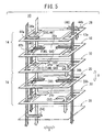
- the flow velocity of the oxidizing gas in the oxidizing gas passages 52 are made higher than that of the oxidizing gas in the oxidizing gas passages 52 by setting the cross-sections of the oxidizing gas passages 52 to be smaller than those of the oxidizing gas passages 56 as shown in FIG. 6. With this configuration, it is possible to effectively improve the drainage characteristic of water liable to be produced in a large amount in the oxidizing gas passages 52 on the low temperature side.
- each of oxidizing gas passages 52a provided in a plate-like second separator 30a may be set to be smaller than that of each of oxidizing gas passages 56a provided in a plate-like intermediate separator 32a. Further, it is possible to make the first and second unit cells 14 and 16 thin, and hence to easily miniaturize the whole cell assembly 10.
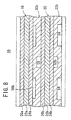
- each of oxidizing gas passages 52b provided in a plate-like second separator 30b may be set to be smaller than that of each of oxidizing gas passages 56b provided in a plate-like intermediate separator 32b. Further, it is possible to increase the contact area between the first and second unit cells 14 and 16, and hence to reduce the contact resistance.
- the number of oxidizing gas passages 52c provided in a plate-like second separator 30c may be set to be smaller than that of oxidizing gas passages 56c provided in a plate-like intermediate separator 32c. Further, like the example shown in FIG. 8, it is possible to effectively increase the contact area between the first and second unit cells 14 and 16.
- the whole size of the fuel cell stack 12 can be easily reduced by miniaturizing each cell assembly 10.
- the miniaturization of the cell assembly 10 is achieved as follows. Firstly, since each of the first and second separators 28 and 30 and the intermediate separator 32 is configured as the metal sheet formed into a corrugated shape (having projections and depressions), the separators can be thinned, with a result that the whole cell assembly 10 can be thinned.
- the intermediate separator 32 has, on the side facing to the first unified body 18, the oxidizing gas passages 56 and also has, on the side facing to the second unified body 20, the fuel gas passages 58 (see FIG. 3), the structure of the intermediate separator 32 is thinner than a separator structure in which the oxidizing gas passages 56 and the fuel gas passages 58 are individually provided in two separators. As a result, it is possible to miniaturize the whole cell assembly 10.
- each of the first and second separators 28 and 30 and the intermediate separator 32 has the oxidizing gas inlet 36a, the oxidizing gas outlet 36b, the fuel gas inlet 42a, and the fuel gas outlet 42b, wherein the oxidizing gas inlets 36a (oxidizing gas outlets 36b, fuel gas inlets 42a, and fuel gas outlets 42b) provided in the separators 28, 30 and 32 are communicated to each other in the stacking direction of the first and second unit cells 14 and 16, and accordingly, it is possible to eliminate the need of provision of a separate manifold (external manifold) outside the cell assembly 10 and also eliminate the need of provision of a seal structure used for the external manifold, and hence to miniaturize the cell assembly 10 and simplify the configuration of the cell assembly 10.
- a separate manifold external manifold
- FIG. 10 is an exploded perspective view of an essential portion of a cell assembly 80 according to a second embodiment of the present invention.
- parts corresponding to those in the cell assembly 10 according to the first embodiment are designated by the same reference numerals and the overlapping description thereof is omitted. The same is true for the following third and later embodiments.
- the cell assembly 80 includes a first unified body 82 and a second unified body 84.
- the first unified body 82 has a hydrocarbon based electrolyte membrane 86
- the second unified body 84 has a fluorine based electrolyte membrane 88.
- the hydrocarbon based electrolyte membrane 86 having a high heat resistance is provided in the first unified body 82, to thereby improve the useful life of the first unified body 82.
- the first unified body 82 can be used for a long period of time, it is possible to enhance the economical merit of the cell assembly 80.
- FIG. 11 is an exploded perspective view of an essential portion of a solid polymer electrolyte fuel cell assembly 100 according to a third embodiment of the present invention.
- the cell assembly 100 is formed by stacking a first unit cell 102 and a second unit cell 104 to each other in the direction A.
- the first unit cell 102 has a first unified body 106
- the second unit cell 104 has a second unified body 108.
- the first unified body 106 is held between a first separator 110 and an intermediate separator 114
- the second unified body 108 is held between the intermediate separator 114 and a second separator 112.
- Each of the first and second unit cells 102 and 104 has, on the one edge side in the long-side direction, oxidizing gas inlets 36a, fuel gas inlets 42a, and coolant inlets 44a, wherein the oxidizing gas inlets 36a (fuel gas inlets 42a, and coolant inlets 44a) are communicated to each other in the direction A, and also has, on the other edge side in the long-side direction, oxidizing gas outlets 36b, fuel gas outlets 42b, and coolant outlets 44b, wherein the oxidizing gas outlets 36b (fuel gas outlets 42b, and coolant outlets 44b) are communicated to each other in the direction A.
- an oxidizing gas, a fuel gas, and a coolant flow in the direction A on the one-edge side in the long-side direction of the cell assembly 100.
- the oxidizing gas and the fuel gas are supplied in the same direction along both surfaces of each of the first and second unified bodies 106 and 108, and after used for reaction, the oxidizing gas and fuel gas are discharged from the other edge side in the long-side direction of the cell assembly 100, to flow in the direction A. Accordingly, since the oxidizing gas and the fuel gas flow in the same direction, it is possible to effectively improve the drainage characteristic of produced water.
- FIG. 13 is an exploded perspective view of an essential portion of a solid polymer electrolyte fuel cell assembly 120 according to a fourth embodiment of the present invention.
- the cell assembly 120 is formed by stacking a first unit cell 122, a second unit cell 124, and a third unit cell 126 to each other in the direction A.
- the first unit cell 122 has a first unified body 106; the second unit cell 124 has a second unified body 108; and the third unit cell 126 has a third unified body 128.
- the first unified body 106 is held between a first separator 110 and a first intermediate separator 114a; the second unified body 108 is held between the first intermediate separator 114a and a second intermediate separator 114b; and the third unified body 128 is held between the second intermediate separator 114b and a second separator 112.
- the temperature of the second unified body 108 tends to be higher than that of each of the first and third unified bodies 106 and 128.
- each of the first and third unified bodies 106 and 128 kept at a relatively low temperature includes a fluorine based electrolyte membrane 86 stable in a low temperature range
- the second unified body 108 kept at a relatively high temperature includes a hydrocarbon based electrolyte membrane 86 withstanding a high temperature.
- each of the first and third unified bodies 106 and 128 since each of the first and third unified bodies 106 and 128 becomes high in humidity, it includes a catalyst layer and a gas diffusion layer each of which is excellent in drainage characteristic, whereas since the second unified body 108 becomes low in humidity, it includes a self-humidifying membrane and a gas diffusion layer having a high water-retention property.
- the cell assembly 120 configured as described above has an effect of improving the performances of cells so as to keep up with different temperature environments by using different kinds of the first, second, and third unified bodies 106, 108, and 128.
- FIG. 14 is an exploded perspective view of an essential portion of a solid polymer electrolyte fuel cell assembly 140 according to a fifth embodiment of the present invention.
- the cell assembly 140 is configured by stacking a first unit cell 142 and a second unit cell 144 to each other.
- the first unit cell 142 has a first unified body 146
- the second unit cell 144 has a second unified body 148.
- the first unified body 146 is held between a first separator 150 and a first intermediate separator 154
- the second unified body 148 is held between a second intermediate separator 156 and a second separator 152.
- a flat baffle plate 158 is interposed between the first and second intermediate separators 154 and 156.
- the cell assembly 140 has, on the one edge side in the long-side direction, fuel gas inlets 42a, oxidizing gas outlets 36b, and fuel gas outlets 42b, wherein the fuel gas inlets 42a (oxidizing gas outlets 36b, and fuel gas outlets 42b) are communicated to each other in the direction A, and also has, on the other edge side in the long-side direction, oxidizing gas inlets 36a, coolant inlets 44a, fuel gas intermediate communication holes 38, and coolant outlets 44b, wherein the oxidizing gas inlets 36a (coolant inlets 44a, fuel gas intermediate communication holes 38, and coolant outlets 44b) are communicated to each other in the direction A.
- Each of the first and second intermediate separators 154 and 156 has, in a surface facing to the baffle plate 158, coolant passages 54 which extend linearly.
- the one-ends of the coolant passages 54 formed in the first intermediate separator 154 are communicated to the coolant inlet 44a of the first intermediate separator 154 and the other ends thereof are returned on the baffle plate 158 and are communicated to the coolant passages 54 formed in the second intermediate separator 156.
- the coolant passages 54 formed in the second intermediate separator 156 are communicated to the coolant outlet 44b of the second intermediate separator 156.
- the coolant is supplied to the first and second unit cells 142 and 144 in series along the flow direction shown in FIG. 15; the fuel gas flows in series from the fuel gas passages 46 formed in the first unit cell 142 to the fuel gas passages 58 formed in the second unit cell 144; and the oxidizing gas flows to the first and second unit cells 142 and 144 individually, that is, in parallel via the oxidizing gas passages 56 and 52.
- the length of the flow passages 46 and 58 becomes longer, to thereby give a sufficiently high pressure drop to the fuel gas, with a result that it is possible to effectively discharge water produced on the anodes 26a and 26b.
- a cell assembly (10) includes a first unit cell (14) and a second unit cell (16) stacked to each other.
- the first unit cell (14) includes a first unified body (18)
- the second unit cell (16) includes a second unified body (20).
- oxidizing gas passages (56) and (52) and fuel gas passages (46) and (58) are provided in parallel along the first and second unit cells (14) and (16).
Landscapes
- Life Sciences & Earth Sciences (AREA)
- Engineering & Computer Science (AREA)
- Manufacturing & Machinery (AREA)
- Sustainable Development (AREA)
- Sustainable Energy (AREA)
- Chemical & Material Sciences (AREA)
- Chemical Kinetics & Catalysis (AREA)
- Electrochemistry (AREA)
- General Chemical & Material Sciences (AREA)
- Fuel Cell (AREA)
Applications Claiming Priority (2)
| Application Number | Priority Date | Filing Date | Title |
|---|---|---|---|
| JP2001061527A JP4344484B2 (ja) | 2001-03-06 | 2001-03-06 | 固体高分子型セルアセンブリ |
| JP2001061527 | 2001-03-06 |
Publications (3)
| Publication Number | Publication Date |
|---|---|
| EP1239530A2 true EP1239530A2 (fr) | 2002-09-11 |
| EP1239530A3 EP1239530A3 (fr) | 2005-10-26 |
| EP1239530B1 EP1239530B1 (fr) | 2012-04-25 |
Family
ID=18920810
Family Applications (1)
| Application Number | Title | Priority Date | Filing Date |
|---|---|---|---|
| EP02004962A Expired - Lifetime EP1239530B1 (fr) | 2001-03-06 | 2002-03-05 | Assemblage de piles à combustible à électrolyte polymère solide, empilement de piles à combustible et procédé pour la fourniture de gaz de réaction dans l'assemblage des piles à combustible |
Country Status (6)
| Country | Link |
|---|---|
| US (1) | US6858338B2 (fr) |
| EP (1) | EP1239530B1 (fr) |
| JP (1) | JP4344484B2 (fr) |
| CA (1) | CA2374466C (fr) |
| RU (1) | RU2269842C2 (fr) |
| TW (1) | TW552737B (fr) |
Cited By (11)
| Publication number | Priority date | Publication date | Assignee | Title |
|---|---|---|---|---|
| EP1416570A1 (fr) * | 2002-10-28 | 2004-05-06 | HONDA MOTOR CO., Ltd. | Empilement de piles à combustible à plaques d'extrémité chauffée |
| WO2003061039A3 (fr) * | 2002-01-10 | 2005-10-13 | Nissan Motor | Pile a combustible et procede associe |
| WO2006030879A1 (fr) * | 2004-09-14 | 2006-03-23 | Nissan Motor Co., Ltd. | Pile a combustible |
| WO2005029622A3 (fr) * | 2003-09-19 | 2006-07-27 | Nissan Motor | Centrale a pile a combustible |
| WO2006088971A1 (fr) * | 2005-02-17 | 2006-08-24 | Ballard Power Systems Inc. | Procede de sechage ameliore pour des empilements de piles a combustible |
| WO2005057697A3 (fr) * | 2003-12-09 | 2007-07-05 | Nissan Motor | Empilement de piles a combustible |
| CN101252201A (zh) * | 2007-02-21 | 2008-08-27 | 三星Sdi株式会社 | 燃料电池组和燃料电池系统 |
| EP2023432A1 (fr) * | 2007-08-10 | 2009-02-11 | Honda Motor Co., Ltd | Pile à combustible |
| US7846609B2 (en) | 2006-11-30 | 2010-12-07 | Samsung Sdi Co., Ltd. | Module-type fuel cell system |
| WO2011026779A3 (fr) * | 2009-09-03 | 2011-07-07 | Theodor Gräbener GmbH & Co. KG | Procédé de thermorégulation d'empilements de piles à combustible ou d'électrolyseurs |
| US8343674B2 (en) | 2007-01-17 | 2013-01-01 | Samsung Sdi Co., Ltd. | Fuel cell system and control method of the same |
Families Citing this family (31)
| Publication number | Priority date | Publication date | Assignee | Title |
|---|---|---|---|---|
| JP4598287B2 (ja) * | 2001-03-06 | 2010-12-15 | 本田技研工業株式会社 | 燃料電池スタックおよび燃料電池スタックの運転方法 |
| JP4516229B2 (ja) * | 2001-03-06 | 2010-08-04 | 本田技研工業株式会社 | 固体高分子型セルアセンブリ |
| US6939639B2 (en) * | 2001-10-01 | 2005-09-06 | Toyota Jidosha Kabushiki Kaisha | Fuel cell separator |
| US20030118888A1 (en) * | 2001-12-05 | 2003-06-26 | Gencell Corporation | Polymer coated metallic bipolar separator plate and method of assembly |
| DE10226609B4 (de) * | 2002-06-14 | 2006-11-30 | Universität Stuttgart | Vorrichtung für eine Trennung oder Synthese von Prozeßstoffen |
| JP4324348B2 (ja) * | 2002-06-28 | 2009-09-02 | 本田技研工業株式会社 | 燃料電池 |
| JP4185734B2 (ja) * | 2002-08-23 | 2008-11-26 | 本田技研工業株式会社 | 燃料電池スタック |
| JP3894109B2 (ja) * | 2002-11-28 | 2007-03-14 | トヨタ自動車株式会社 | 燃料電池 |
| JP4630529B2 (ja) * | 2003-06-13 | 2011-02-09 | 本田技研工業株式会社 | 燃料電池システム |
| CN100397690C (zh) | 2003-06-24 | 2008-06-25 | 松下电器产业株式会社 | 高分子电解质型燃料电池 |
| GB0315686D0 (en) * | 2003-07-04 | 2003-08-13 | Honeywell Normalair Garrett | Ionic conduction device |
| US20050069749A1 (en) * | 2003-08-15 | 2005-03-31 | David Frank | Flow field plate arrangement |
| JP5000073B2 (ja) * | 2003-09-08 | 2012-08-15 | 本田技研工業株式会社 | 燃料電池スタックの氷点下起動方法、燃料電池スタックの氷点下起動システム、および燃料電池スタックの設計方法 |
| JP2005222809A (ja) * | 2004-02-05 | 2005-08-18 | Nissan Motor Co Ltd | 燃料電池 |
| KR100599715B1 (ko) | 2004-06-23 | 2006-07-12 | 삼성에스디아이 주식회사 | 연료전지 시스템, 스택, 및 세퍼레이터 |
| JP4889983B2 (ja) * | 2005-09-02 | 2012-03-07 | 本田技研工業株式会社 | 燃料電池 |
| US8470480B2 (en) * | 2005-12-29 | 2013-06-25 | Michael L. Perry | Circulation of gas-entrained fuel cell coolant |
| RU2328797C1 (ru) * | 2007-03-09 | 2008-07-10 | Общество с ограниченной ответственностью "Национальная инновационная компания "Новые энергетические проекты" | Мембранно-электродный блок (мэб) для кислородно(воздушно)-водородного топливного элемента и способ его изготовления |
| JP5127422B2 (ja) * | 2007-12-05 | 2013-01-23 | 本田技研工業株式会社 | 燃料電池 |
| JP5434035B2 (ja) * | 2008-10-02 | 2014-03-05 | 日産自動車株式会社 | 燃料電池のスタック構造 |
| JP4572252B2 (ja) * | 2008-10-30 | 2010-11-04 | 本田技研工業株式会社 | 燃料電池スタック |
| US9153825B2 (en) * | 2008-12-02 | 2015-10-06 | Panasonic Intellectual Property Management Co., Ltd. | Fuel cell |
| JP5336210B2 (ja) * | 2009-01-26 | 2013-11-06 | 本田技研工業株式会社 | 燃料電池スタック |
| JP2010212216A (ja) * | 2009-03-12 | 2010-09-24 | Toyota Motor Corp | 燃料電池 |
| JP2010212215A (ja) * | 2009-03-12 | 2010-09-24 | Toyota Motor Corp | 燃料電池 |
| JP4516630B2 (ja) * | 2010-03-25 | 2010-08-04 | 本田技研工業株式会社 | 固体高分子型セルアセンブリ |
| JP5280468B2 (ja) * | 2011-02-04 | 2013-09-04 | 本田技研工業株式会社 | 燃料電池 |
| RU2504868C2 (ru) * | 2012-04-28 | 2014-01-20 | Открытое акционерное общество "Объединенная авиастроительная корпорация" | Топливный элемент и батарея топливных элементов |
| JP6071680B2 (ja) * | 2013-03-22 | 2017-02-01 | 本田技研工業株式会社 | 燃料電池スタックの運転方法 |
| EP3306721B1 (fr) | 2015-06-03 | 2023-07-12 | Nissan Motor Co., Ltd. | Corps de structure de séparateur métallique pour une pile à combustible, pile à combustible et empilement de piles à combustible utilisant ce même corps de structure de séparateur |
| FR3157015B1 (fr) * | 2023-12-18 | 2025-11-21 | Commissariat Energie Atomique | Pile à combustible comportant un empilement de cellules électrochimiques et plusieurs collecteurs d’entrée et de sortie pour chaque fluide réactif et pour le fluide caloporteur |
Citations (3)
| Publication number | Priority date | Publication date | Assignee | Title |
|---|---|---|---|---|
| JPH04355061A (ja) | 1991-05-31 | 1992-12-09 | Ishikawajima Harima Heavy Ind Co Ltd | 燃料電池 |
| US5773160A (en) | 1994-06-24 | 1998-06-30 | Ballard Power Systems Inc. | Electrochemical fuel cell stack with concurrent flow of coolant and oxidant streams and countercurrent flow of fuel and oxidant streams |
| EP0967675A2 (fr) | 1998-06-26 | 1999-12-29 | Toyota Jidosha Kabushiki Kaisha | Pile à combustible, séparateur pour celle-ci et méthode de distribution de gaz dans une pile à combustible |
Family Cites Families (18)
| Publication number | Priority date | Publication date | Assignee | Title |
|---|---|---|---|---|
| NL8602823A (nl) * | 1985-11-08 | 1987-06-01 | Toshiba Kk | Gesmolten carbonaatbrandstofcel. |
| JPS63248073A (ja) * | 1987-04-01 | 1988-10-14 | Fuji Electric Co Ltd | 積層形燃料電池 |
| JPH01151163A (ja) * | 1987-12-07 | 1989-06-13 | Fuji Electric Co Ltd | 燃料電池 |
| JP2966548B2 (ja) * | 1991-03-01 | 1999-10-25 | 大阪瓦斯株式会社 | 燃料電池 |
| AU671722B2 (en) * | 1992-11-25 | 1996-09-05 | Michael S. Hsu | Radiant thermal integration with regenerative heating in a high temperature electrochemical covverter |
| RU2084991C1 (ru) * | 1993-03-01 | 1997-07-20 | Российский федеральный ядерный центр - Всероссийский научно-исследовательский институт ядерной физики | Батарея твердотопливных элементов |
| JP4037448B2 (ja) * | 1995-05-25 | 2008-01-23 | 本田技研工業株式会社 | 燃料電池 |
| US5686199A (en) * | 1996-05-07 | 1997-11-11 | Alliedsignal Inc. | Flow field plate for use in a proton exchange membrane fuel cell |
| JPH1167258A (ja) * | 1997-08-27 | 1999-03-09 | Toshiba Corp | 燃料電池 |
| CA2299474C (fr) * | 1997-10-14 | 2007-10-09 | Nisshin Steel Co., Ltd. | Separateur pour cellule electrochimique a basse temperature et procede de production dudit separateur |
| RU2138885C1 (ru) * | 1997-11-05 | 1999-09-27 | Миллер Олег Олегович | Блок сборок твердооксидных топливных элементов с коэффициентом температурного расширения (ктр), превышающим ктр их электролита |
| JP2000030730A (ja) * | 1998-07-08 | 2000-01-28 | Toyota Motor Corp | 燃料電池 |
| JP3548447B2 (ja) * | 1999-01-12 | 2004-07-28 | ニチアス株式会社 | 燃料電池用セパレータ及びその作製方法 |
| DE19905564C2 (de) * | 1999-02-11 | 2001-06-28 | Forschungszentrum Juelich Gmbh | Brennstoffzellenstapel mit Zuführungs- und/oder Abführungskanälen |
| AT407589B (de) * | 1999-11-03 | 2001-04-25 | Vaillant Gmbh | Brennstoffzelle |
| JP3389551B2 (ja) * | 2000-04-19 | 2003-03-24 | 三洋電機株式会社 | 固体高分子型燃料電池 |
| JP4516229B2 (ja) * | 2001-03-06 | 2010-08-04 | 本田技研工業株式会社 | 固体高分子型セルアセンブリ |
| JP4598287B2 (ja) * | 2001-03-06 | 2010-12-15 | 本田技研工業株式会社 | 燃料電池スタックおよび燃料電池スタックの運転方法 |
-
2001
- 2001-03-06 JP JP2001061527A patent/JP4344484B2/ja not_active Expired - Lifetime
-
2002
- 2002-03-05 TW TW091104020A patent/TW552737B/zh not_active IP Right Cessation
- 2002-03-05 EP EP02004962A patent/EP1239530B1/fr not_active Expired - Lifetime
- 2002-03-05 CA CA002374466A patent/CA2374466C/fr not_active Expired - Fee Related
- 2002-03-06 US US10/093,235 patent/US6858338B2/en not_active Expired - Lifetime
- 2002-03-06 RU RU2002106225/09A patent/RU2269842C2/ru not_active IP Right Cessation
Patent Citations (3)
| Publication number | Priority date | Publication date | Assignee | Title |
|---|---|---|---|---|
| JPH04355061A (ja) | 1991-05-31 | 1992-12-09 | Ishikawajima Harima Heavy Ind Co Ltd | 燃料電池 |
| US5773160A (en) | 1994-06-24 | 1998-06-30 | Ballard Power Systems Inc. | Electrochemical fuel cell stack with concurrent flow of coolant and oxidant streams and countercurrent flow of fuel and oxidant streams |
| EP0967675A2 (fr) | 1998-06-26 | 1999-12-29 | Toyota Jidosha Kabushiki Kaisha | Pile à combustible, séparateur pour celle-ci et méthode de distribution de gaz dans une pile à combustible |
Cited By (16)
| Publication number | Priority date | Publication date | Assignee | Title |
|---|---|---|---|---|
| WO2003061039A3 (fr) * | 2002-01-10 | 2005-10-13 | Nissan Motor | Pile a combustible et procede associe |
| US7309539B2 (en) | 2002-10-28 | 2007-12-18 | Honda Motor Co., Ltd. | Fuel cell stack |
| EP1416570A1 (fr) * | 2002-10-28 | 2004-05-06 | HONDA MOTOR CO., Ltd. | Empilement de piles à combustible à plaques d'extrémité chauffée |
| WO2005029622A3 (fr) * | 2003-09-19 | 2006-07-27 | Nissan Motor | Centrale a pile a combustible |
| WO2005057697A3 (fr) * | 2003-12-09 | 2007-07-05 | Nissan Motor | Empilement de piles a combustible |
| WO2006030879A1 (fr) * | 2004-09-14 | 2006-03-23 | Nissan Motor Co., Ltd. | Pile a combustible |
| US7659017B2 (en) | 2005-02-17 | 2010-02-09 | Daimier Ag | Drying method for fuel cell stacks |
| WO2006088971A1 (fr) * | 2005-02-17 | 2006-08-24 | Ballard Power Systems Inc. | Procede de sechage ameliore pour des empilements de piles a combustible |
| US7846609B2 (en) | 2006-11-30 | 2010-12-07 | Samsung Sdi Co., Ltd. | Module-type fuel cell system |
| US8343674B2 (en) | 2007-01-17 | 2013-01-01 | Samsung Sdi Co., Ltd. | Fuel cell system and control method of the same |
| EP1962363A3 (fr) * | 2007-02-21 | 2009-07-15 | Samsung SDI Co., Ltd. | Pile à combustible et bloc de piles à combustible |
| EP1962363A2 (fr) | 2007-02-21 | 2008-08-27 | Samsung SDI Co., Ltd. | Pile à combustible et bloc de piles à combustible |
| CN101252201A (zh) * | 2007-02-21 | 2008-08-27 | 三星Sdi株式会社 | 燃料电池组和燃料电池系统 |
| EP2023432A1 (fr) * | 2007-08-10 | 2009-02-11 | Honda Motor Co., Ltd | Pile à combustible |
| US8802312B2 (en) | 2007-08-10 | 2014-08-12 | Honda Motor Co., Ltd. | Fuel cell separators capable of suppressing variation in pressure loss |
| WO2011026779A3 (fr) * | 2009-09-03 | 2011-07-07 | Theodor Gräbener GmbH & Co. KG | Procédé de thermorégulation d'empilements de piles à combustible ou d'électrolyseurs |
Also Published As
| Publication number | Publication date |
|---|---|
| US6858338B2 (en) | 2005-02-22 |
| CA2374466C (fr) | 2009-06-16 |
| CA2374466A1 (fr) | 2002-09-06 |
| US20020146601A1 (en) | 2002-10-10 |
| RU2269842C2 (ru) | 2006-02-10 |
| EP1239530A3 (fr) | 2005-10-26 |
| TW552737B (en) | 2003-09-11 |
| JP4344484B2 (ja) | 2009-10-14 |
| EP1239530B1 (fr) | 2012-04-25 |
| JP2002260689A (ja) | 2002-09-13 |
Similar Documents
| Publication | Publication Date | Title |
|---|---|---|
| CA2374466C (fr) | Ensemble de piles a combustible a electrolyte a polymere solide, rangee de piles et methode d'alimentation du gaz reactif dans la pile a combustible | |
| EP1371107B1 (fr) | Ensemble de piles a combustible a electrolyte polymere solide connectées en série et procede d'alimentation en gaz de reaction dans la pile a combustible | |
| US7687165B2 (en) | Solid polymer electrolyte fuel cell assembly, fuel cell stack, and method of operating cell assembly | |
| JP4205774B2 (ja) | 燃料電池 | |
| CA2578009C (fr) | Pile a combustible pourvue d'une surface inclinee | |
| AU2002234964A1 (en) | Solid polymer electrolyte fuel cell assembly, fuel cell stack, and method of supplying reaction gas in fuel cell | |
| US7022430B2 (en) | Compact fuel cell with improved fluid supply | |
| JP3971969B2 (ja) | 固体高分子型燃料電池 | |
| US11811104B2 (en) | Bipolar plate with undulating channels | |
| US20060003220A1 (en) | Fuel cell | |
| US20050186459A1 (en) | Fuel cell | |
| US7846613B2 (en) | Fuel cell with separator having a ridge member | |
| US8802312B2 (en) | Fuel cell separators capable of suppressing variation in pressure loss | |
| US7572538B2 (en) | Fuel cell | |
| US20060003206A1 (en) | Fuel cell | |
| JP2003338299A (ja) | 燃料電池 | |
| JP2006236612A (ja) | 燃料電池 | |
| JP2004087190A (ja) | 固体高分子型セルアセンブリ | |
| KR20050093173A (ko) | 연료전지용 분리판 및 그 분리판이 구비된 연료전지 |
Legal Events
| Date | Code | Title | Description |
|---|---|---|---|
| PUAI | Public reference made under article 153(3) epc to a published international application that has entered the european phase |
Free format text: ORIGINAL CODE: 0009012 |
|
| AK | Designated contracting states |
Kind code of ref document: A2 Designated state(s): AT BE CH CY DE DK ES FI FR GB GR IE IT LI LU MC NL PT SE TR |
|
| AX | Request for extension of the european patent |
Free format text: AL;LT;LV;MK;RO;SI |
|
| RIC1 | Information provided on ipc code assigned before grant |
Ipc: 7H 01M 8/10 B Ipc: 7H 01M 8/04 B Ipc: 7H 01M 8/24 A |
|
| PUAL | Search report despatched |
Free format text: ORIGINAL CODE: 0009013 |
|
| AK | Designated contracting states |
Kind code of ref document: A3 Designated state(s): AT BE CH CY DE DK ES FI FR GB GR IE IT LI LU MC NL PT SE TR |
|
| AX | Request for extension of the european patent |
Extension state: AL LT LV MK RO SI |
|
| 17P | Request for examination filed |
Effective date: 20051209 |
|
| AKX | Designation fees paid |
Designated state(s): DE FR GB IT |
|
| GRAP | Despatch of communication of intention to grant a patent |
Free format text: ORIGINAL CODE: EPIDOSNIGR1 |
|
| GRAS | Grant fee paid |
Free format text: ORIGINAL CODE: EPIDOSNIGR3 |
|
| GRAA | (expected) grant |
Free format text: ORIGINAL CODE: 0009210 |
|
| RIN1 | Information on inventor provided before grant (corrected) |
Inventor name: SUGITA, NARUTOSHI Inventor name: ENJOJI, NAOYUKI Inventor name: WARIISHI, YOSHINORI Inventor name: SUGIURA, SEIJI |
|
| AK | Designated contracting states |
Kind code of ref document: B1 Designated state(s): DE FR GB IT |
|
| REG | Reference to a national code |
Ref country code: GB Ref legal event code: FG4D |
|
| REG | Reference to a national code |
Ref country code: DE Ref legal event code: R096 Ref document number: 60242717 Country of ref document: DE Effective date: 20120614 |
|
| REG | Reference to a national code |
Ref country code: GB Ref legal event code: 746 Effective date: 20121113 |
|
| REG | Reference to a national code |
Ref country code: DE Ref legal event code: R084 Ref document number: 60242717 Country of ref document: DE Effective date: 20121113 |
|
| PG25 | Lapsed in a contracting state [announced via postgrant information from national office to epo] |
Ref country code: IT Free format text: LAPSE BECAUSE OF FAILURE TO SUBMIT A TRANSLATION OF THE DESCRIPTION OR TO PAY THE FEE WITHIN THE PRESCRIBED TIME-LIMIT Effective date: 20120425 |
|
| PLBE | No opposition filed within time limit |
Free format text: ORIGINAL CODE: 0009261 |
|
| STAA | Information on the status of an ep patent application or granted ep patent |
Free format text: STATUS: NO OPPOSITION FILED WITHIN TIME LIMIT |
|
| 26N | No opposition filed |
Effective date: 20130128 |
|
| REG | Reference to a national code |
Ref country code: DE Ref legal event code: R097 Ref document number: 60242717 Country of ref document: DE Effective date: 20130128 |
|
| REG | Reference to a national code |
Ref country code: FR Ref legal event code: ST Effective date: 20131129 |
|
| PG25 | Lapsed in a contracting state [announced via postgrant information from national office to epo] |
Ref country code: FR Free format text: LAPSE BECAUSE OF NON-PAYMENT OF DUE FEES Effective date: 20130402 |
|
| PGFP | Annual fee paid to national office [announced via postgrant information from national office to epo] |
Ref country code: GB Payment date: 20170301 Year of fee payment: 16 |
|
| GBPC | Gb: european patent ceased through non-payment of renewal fee |
Effective date: 20180305 |
|
| PG25 | Lapsed in a contracting state [announced via postgrant information from national office to epo] |
Ref country code: GB Free format text: LAPSE BECAUSE OF NON-PAYMENT OF DUE FEES Effective date: 20180305 |
|
| PGFP | Annual fee paid to national office [announced via postgrant information from national office to epo] |
Ref country code: DE Payment date: 20190219 Year of fee payment: 18 |
|
| REG | Reference to a national code |
Ref country code: DE Ref legal event code: R119 Ref document number: 60242717 Country of ref document: DE |
|
| PG25 | Lapsed in a contracting state [announced via postgrant information from national office to epo] |
Ref country code: DE Free format text: LAPSE BECAUSE OF NON-PAYMENT OF DUE FEES Effective date: 20201001 |