EP1239544A2 - Appareil électrique avec section de contact à bus - Google Patents
Appareil électrique avec section de contact à bus Download PDFInfo
- Publication number
- EP1239544A2 EP1239544A2 EP02003071A EP02003071A EP1239544A2 EP 1239544 A2 EP1239544 A2 EP 1239544A2 EP 02003071 A EP02003071 A EP 02003071A EP 02003071 A EP02003071 A EP 02003071A EP 1239544 A2 EP1239544 A2 EP 1239544A2
- Authority
- EP
- European Patent Office
- Prior art keywords
- bus conductor
- circuit board
- connections
- electronic circuit
- section according
- Prior art date
- Legal status (The legal status is an assumption and is not a legal conclusion. Google has not performed a legal analysis and makes no representation as to the accuracy of the status listed.)
- Granted
Links
Images



Classifications
-
- H—ELECTRICITY
- H05—ELECTRIC TECHNIQUES NOT OTHERWISE PROVIDED FOR
- H05K—PRINTED CIRCUITS; CASINGS OR CONSTRUCTIONAL DETAILS OF ELECTRIC APPARATUS; MANUFACTURE OF ASSEMBLAGES OF ELECTRICAL COMPONENTS
- H05K7/00—Constructional details common to different types of electric apparatus
- H05K7/14—Mounting supporting structure in casing or on frame or rack
- H05K7/1462—Mounting supporting structure in casing or on frame or rack for programmable logic controllers [PLC] for automation or industrial process control
- H05K7/1475—Bus assemblies for establishing communication between PLC modules
- H05K7/1478—Bus assemblies for establishing communication between PLC modules including a segmented bus
-
- H—ELECTRICITY
- H01—ELECTRIC ELEMENTS
- H01R—ELECTRICALLY-CONDUCTIVE CONNECTIONS; STRUCTURAL ASSOCIATIONS OF A PLURALITY OF MUTUALLY-INSULATED ELECTRICAL CONNECTING ELEMENTS; COUPLING DEVICES; CURRENT COLLECTORS
- H01R9/00—Structural associations of a plurality of mutually-insulated electrical connecting elements, e.g. terminal strips or terminal blocks; Terminals or binding posts mounted upon a base or in a case; Bases therefor
- H01R9/22—Bases, e.g. strip, block, panel
- H01R9/24—Terminal blocks
- H01R9/26—Clip-on terminal blocks for side-by-side rail- or strip-mounting
- H01R9/2625—Clip-on terminal blocks for side-by-side rail- or strip-mounting with built-in electrical component
- H01R9/2658—Clip-on terminal blocks for side-by-side rail- or strip-mounting with built-in electrical component with built-in data-bus connection
-
- H—ELECTRICITY
- H01—ELECTRIC ELEMENTS
- H01R—ELECTRICALLY-CONDUCTIVE CONNECTIONS; STRUCTURAL ASSOCIATIONS OF A PLURALITY OF MUTUALLY-INSULATED ELECTRICAL CONNECTING ELEMENTS; COUPLING DEVICES; CURRENT COLLECTORS
- H01R9/00—Structural associations of a plurality of mutually-insulated electrical connecting elements, e.g. terminal strips or terminal blocks; Terminals or binding posts mounted upon a base or in a case; Bases therefor
- H01R9/22—Bases, e.g. strip, block, panel
- H01R9/24—Terminal blocks
- H01R9/26—Clip-on terminal blocks for side-by-side rail- or strip-mounting
- H01R9/2675—Electrical interconnections between two blocks, e.g. by means of busbars
Definitions
- the innovation concerns an electrical device with a modular structure for control and / or monitoring of technical processes and / or for industrial and / or building automation, for the forwarding of bus conductor signals and / or supply voltages has an internal bus conductor section.
- a bus conductor section for an electrical device is known from EP 95 113 729 A2.
- the internal bus conductor section as continuous circuit board is formed with conductor tracks thereon, serve Terminal blocks that can be arranged on mounting rails for signal adaptation between one higher-level fieldbus and initiators, field devices connected to the connection blocks or similar.
- the connection blocks are made of functionally different connection or module disks assembled, whereby between protective conductor disks, A distinction is made between the feed washers, the supply / signal conductor washers and the locking foot washers becomes.
- One or more connection blocks are connected via the internal bus conductor a connection module for the fieldbus can be connected.
- bus conductor section is known from EP 00 100 303.
- the bus conductor sections of the individual basic terminal supports are structural formed separately from each other and each have a circuit board, which by at least a series of metal pins is interspersed, which is on one side of the board essentially vertical and on the opposite side of the board are aligned substantially parallel to the board, the at least one perpendicular the pin row extending to the board is dimensioned such that its pin row ends can be used directly to contact a socket strip.
- the structural separation of the Bus conductor sections of each module disc initially have the advantage of almost any one
- the bus conductor sections can also be connected with one another, thus increasing the variability of the entire module system.
- the chosen structural design brings of the bus conductor section with a circuit board and the board penetrating Angle pins of special length have the advantage that separate connector elements for contacting a separate one or one molded onto an electronic circuit board Device connector can be omitted.
- the invention solves this problem by the subject matter of claim 1. It creates an electrical device with a modular structure for control and / or monitoring technical processes and / or for industrial and / or building automation, the an internal one for forwarding bus conductor signals and / or supply voltages Has bus conductor section, with at least one that can be placed on a mounting rail Connection module with connections for external conductors and with a row of disc-shaped ones Basic terminal support, each with a preferably pluggable electronic circuit board have, which can be connected to an internal bus conductor, wherein the electronic circuit board is aligned essentially perpendicular to the mounting rail, the internal bus conductor sections of the individual base terminal supports are formed separately from each other and one arranged in the base terminal support Have circuit board, on which at least two directly one above the other Rows of connections for passing on the bus conductor signals and / or supply voltages between adjacent connection modules and at least one or more - in this case directly one above the other - rows of connections for passing on the bus conductor signals and / or supply voltages between the
- the multi-row of the connections also offers the possibility of a problem-free Variation of contact sizes. Due to different contact sizes, the internal In this way, bus conductors can easily meet various current-carrying capacity requirements adaptable.
- the solder connections can be of any design, e.g. by contacting and / or in SMD technology. Instead of the socket and pin headers between Post connectors can also be used in the neighboring modules.
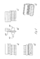
- Fig. 1 shows a module disc for a device not otherwise shown here Automation technology.
- the device includes a gateway (not shown here) which among other things the module disks are stackable.
- the module disc is with others Module disks can be joined to form a connection block of variable length.
- the module disc has a disc-shaped base clamp carrier 2 for locking the individual module on a mounting rail (not shown here) on.
- the base terminal support 2 is provided with plastic locking feet 4, with which the locking connection to the mounting rail can be produced in a manner known per se.
- the base clamp support 2 comprises a lower base section 6, which is in an area above the mounting rail feet 4 and next to the mounting rail feet 4 extends on both sides beyond the mounting rail.
- the basic terminal support 2 perpendicular penetration to its main plane of extent or bus conductor opening 8 for receiving the internal bus conductor section 10 provided that the bus conductor signals are forwarded from individual module to individual module and in the pluggable electronic circuit board 14, which is perpendicular to the mounting rail extension direction is aligned.
- the electronic circuit board 14 is in the area which is approximately from the vertical to the center of the mounting rail to the internal bus conductor section 10 extends, in the base terminal support 2, a peripheral recess 12 educated.
- the electronic circuit board 14 is provided with a (not shown here) Electronic circuit for processing / forwarding of each to the electronic circuit board 14 provided signals.
- the recess 12 is at the end of the individual module facing away from the mounting rail bounded by a web 26 projecting perpendicularly from the base section 6, on its side facing the mounting rail 4 with an insertion groove 28 for insertion an electronics housing, not shown, is provided.
- connection section 30 protruding vertically upward from the base section 6 formed.
- a recess 62 enables the insertion of a coding element.
- the internal bus conductor section 10 of each base terminal carrier inserted into the opening 8 2 each has a circuit board 102 (see also FIG. 3), perpendicular to of the two two rows of connections 104a, b; 106a, b to Forwarding of the bus conductor signals and / or supply voltages between neighboring ones Connection modules and parallel to the example here two directly one above the other Rows of connections 108a, b for passing on the bus conductor signals and / or supply voltages between the internal bus conductor and the electronic circuit board are trained.
- the circuit board 102 is essentially parallel to the electronic circuit board of the connection module aligned. It lies essentially in the level of the electronic circuit board 14 in its main extension plane and connects directly to the electronic circuit board 14 on.
- connection of the internal bus conductor to neighboring module panes are made by a double row header 110 and a double row header 112 is formed, the plug connector strip being located next to one another in the case of base terminal supports 2 112 into the socket strip 110 of the bus conductor section 10 of each engages adjacent base terminal support 2.
- socket and Pin headers are also possible.
- This double row arrangement can also be realized by a single post connector if no offset of the signal and / or supply lines is required becomes.
- the circuit board 102 is in the opening 8 of the base terminal support 2 can be used, which can be closed by a closure part 114, which in turn has an opening 116 for the at least two superimposed ones Rows of connections to the neighboring module pane and a guide lug 117 which engages in a corresponding recess 119 of the neighboring module pane.
- a double-row socket strip 118 is arranged on the circuit board 102, which for contacting a likewise double-row pin header 120 on the Electronic circuit board 14 is used.
- This arrangement is to be understood as an example and can also be implemented the other way round (plug connector on the circuit board 102).
- a contact strip can also be provided on both sides of the electronic circuit board intended to be 14.
- connections 104, 106 and 108 are provided twice, the connections 108 each offset between adjacent connections 104, 106 lie (locking offset). So there are 14 adjacent lines in a small space arranged, depending on the application, not all of these lines are used and / or must be passed on to the electronic circuit board.
- connections 108 to pass on the bus conductor signals and / or supply voltages between the internal bus conductor 10 and the Printed circuit board 102 only has contact surfaces as conductor tracks on the edge of the electronic printed circuit board 14 represent and via a circuit board edge connector on the electronic circuit board 14 are connected.
Landscapes
- Engineering & Computer Science (AREA)
- Automation & Control Theory (AREA)
- Microelectronics & Electronic Packaging (AREA)
- Coupling Device And Connection With Printed Circuit (AREA)
- Connections Arranged To Contact A Plurality Of Conductors (AREA)
- Connection Or Junction Boxes (AREA)
- Patch Boards (AREA)
- Combinations Of Printed Boards (AREA)
- Multi-Conductor Connections (AREA)
Applications Claiming Priority (2)
| Application Number | Priority Date | Filing Date | Title |
|---|---|---|---|
| DE20103978U | 2001-03-07 | ||
| DE20103978U DE20103978U1 (de) | 2001-03-07 | 2001-03-07 | Elektrisches Gerät mit Busleiterabschnitt |
Publications (3)
| Publication Number | Publication Date |
|---|---|
| EP1239544A2 true EP1239544A2 (fr) | 2002-09-11 |
| EP1239544A3 EP1239544A3 (fr) | 2005-08-10 |
| EP1239544B1 EP1239544B1 (fr) | 2006-11-22 |
Family
ID=7953980
Family Applications (1)
| Application Number | Title | Priority Date | Filing Date |
|---|---|---|---|
| EP02003071A Expired - Lifetime EP1239544B1 (fr) | 2001-03-07 | 2002-02-13 | Appareil électrique avec section de contact à bus |
Country Status (4)
| Country | Link |
|---|---|
| US (1) | US6575771B2 (fr) |
| EP (1) | EP1239544B1 (fr) |
| AT (1) | ATE346397T1 (fr) |
| DE (2) | DE20103978U1 (fr) |
Cited By (1)
| Publication number | Priority date | Publication date | Assignee | Title |
|---|---|---|---|---|
| DE102009015508A1 (de) | 2009-04-02 | 2010-10-14 | Phoenix Contact Gmbh & Co. Kg | Verbindungssystem für Steuermodule |
Families Citing this family (14)
| Publication number | Priority date | Publication date | Assignee | Title |
|---|---|---|---|---|
| US6425770B1 (en) * | 2000-04-14 | 2002-07-30 | Rockwell Automation Technologies, Inc. | Input/output device having removable module |
| EP1317783B1 (fr) * | 2000-09-12 | 2006-10-18 | Tyco Electronics AMP GmbH | Systeme de raccord modulaire pour applications ethernet dans le secteur industriel |
| DE10249981B3 (de) * | 2002-10-26 | 2004-04-01 | Moeller Gmbh | Elektronische Steuereinrichtung mit Mitteln zur Ableitung von Störsignalen |
| US6790079B2 (en) * | 2002-11-21 | 2004-09-14 | International Business Machines Corporation | Method, apparatus, and system of card and connector retention |
| DE20319657U1 (de) * | 2003-12-18 | 2005-04-28 | Weidmüller Interface GmbH & Co. KG | Verteilerkasten mit Anschlußvorrichtung zum Anschluß von Feldgeräten |
| DE202005010601U1 (de) * | 2005-07-06 | 2006-11-16 | Weidmüller Interface GmbH & Co. KG | Modulgehäuse, insbesondere Modulsockelgehäuse, zum Aufrasten auf eine im Querschnitt hutförmige Tragschiene |
| EP2086077A3 (fr) * | 2008-02-02 | 2013-07-24 | Weidmüller Interface GmbH & Co. KG | Système de montage pour composants électriques et/ou mécaniques |
| KR101335178B1 (ko) * | 2009-12-08 | 2013-12-02 | 에이비비 테크놀로지 아게 | I/o 모듈 |
| US8715017B1 (en) * | 2012-02-08 | 2014-05-06 | Phoenix Contact Development and Manufacturing, Inc. | Terminal block having an extender body fitted to a contact body |
| ITMI20120457A1 (it) * | 2012-03-23 | 2013-09-24 | Morsettitalia Spa | Contenitore per circuiti elettrici/elettronici dotato di sedi e relativi elementi di contatto per connettori di cablaggio elettrico |
| US9136648B2 (en) * | 2012-07-12 | 2015-09-15 | Rockwell Automation Technologies, Inc. | Din or panel ground integral to connector body |
| EP3050170B1 (fr) | 2013-09-27 | 2023-04-19 | Siemens Aktiengesellschaft | Dispositif de couplage d'un bus plc |
| DE102013111571B4 (de) | 2013-10-21 | 2016-11-17 | Wago Verwaltungsgesellschaft Mbh | Gerätegehäuse, Elektronikgeräte und Steckkontaktträger |
| TWM590795U (zh) * | 2019-08-22 | 2020-02-11 | 映興電子股份有限公司 | 連接器結構 |
Family Cites Families (15)
| Publication number | Priority date | Publication date | Assignee | Title |
|---|---|---|---|---|
| DE3633785A1 (de) * | 1986-10-03 | 1988-04-07 | Siemens Ag | Automatisierungsgeraet |
| DE4140611C1 (en) * | 1991-12-10 | 1993-05-27 | Kloeckner-Moeller Gmbh, 5300 Bonn, De | Bus contacting device for modular control system - comprises modular blocks with three-point contact for connecting bus board of module to contact surface of pcb surrounded by housing shell |
| EP0661915A1 (fr) * | 1993-12-28 | 1995-07-05 | RKC Instruments Inc. | Dispositif de commande modulaire |
| DE4438804C1 (de) * | 1994-10-31 | 1996-03-28 | Weidmueller Interface | Modulare Steuerungsanlage mit Busleiter z. B. zur Gebäudeautomatisierung |
| DE4440102C1 (de) | 1994-11-10 | 1996-05-15 | Weidmueller Interface | Modulare Steuerungsanlage mit integriertem Feldbusanschluß |
| DE29624219U1 (de) * | 1996-01-12 | 2001-03-01 | Phoenix Contact Gmbh & Co., 32825 Blomberg | Bussystem |
| DE19710768C2 (de) * | 1997-03-16 | 1999-11-11 | Phoenix Contact Gmbh & Co | Elektrisches oder elektronisches Gerät |
| DE19748531A1 (de) * | 1997-11-03 | 1999-05-06 | Siemens Ag | Aufbausystem für Verbraucherabzweige mit stehender Verdrahtung |
| DE19748429A1 (de) * | 1997-11-03 | 1999-05-06 | Siemens Ag | Kommunikationsfähige Schaltgeräteeinheit |
| DE19748530B9 (de) * | 1997-11-03 | 2004-09-09 | Siemens Ag | Modulares Automatisierungsgerät und Baugruppe eines modularen Automatisierungsgerätes |
| DE19807710C2 (de) * | 1998-02-24 | 2002-07-18 | Siemens Ag | Modulares Automatisierungsgerät und Baugruppe eines modularen Automatisierungsgerätes |
| DE19838493C1 (de) * | 1998-08-25 | 2000-05-11 | Stahl R Schaltgeraete Gmbh | Anreihbare Busschiene |
| DE19902745B4 (de) * | 1999-01-25 | 2004-01-15 | Weidmüller Interface Gmbh & Co. | Elektrisches Gerät |
| DE29901194U1 (de) * | 1999-01-25 | 1999-05-20 | Weidmüller Interface GmbH & Co., 32760 Detmold | Busleiterabschnitt für ein elektrisches Gerät |
| JP3388718B2 (ja) * | 1999-08-03 | 2003-03-24 | エスエムシー株式会社 | シリアル−パラレル信号変換入出力装置 |
-
2001
- 2001-03-07 DE DE20103978U patent/DE20103978U1/de not_active Expired - Lifetime
-
2002
- 2002-02-13 DE DE50208740T patent/DE50208740D1/de not_active Expired - Lifetime
- 2002-02-13 EP EP02003071A patent/EP1239544B1/fr not_active Expired - Lifetime
- 2002-02-13 AT AT02003071T patent/ATE346397T1/de not_active IP Right Cessation
- 2002-03-01 US US10/084,887 patent/US6575771B2/en not_active Expired - Lifetime
Cited By (2)
| Publication number | Priority date | Publication date | Assignee | Title |
|---|---|---|---|---|
| DE102009015508A1 (de) | 2009-04-02 | 2010-10-14 | Phoenix Contact Gmbh & Co. Kg | Verbindungssystem für Steuermodule |
| DE102009015508B4 (de) * | 2009-04-02 | 2015-06-18 | Phoenix Contact Gmbh & Co. Kg | Verbindungssystem für Steuermodule |
Also Published As
| Publication number | Publication date |
|---|---|
| EP1239544B1 (fr) | 2006-11-22 |
| DE50208740D1 (de) | 2007-01-04 |
| ATE346397T1 (de) | 2006-12-15 |
| DE20103978U1 (de) | 2002-07-11 |
| US6575771B2 (en) | 2003-06-10 |
| US20020127895A1 (en) | 2002-09-12 |
| EP1239544A3 (fr) | 2005-08-10 |
Similar Documents
| Publication | Publication Date | Title |
|---|---|---|
| DE3909263C2 (fr) | ||
| EP1022934B1 (fr) | Tronçon de bus pour appareil électrique | |
| EP1239544B1 (fr) | Appareil électrique avec section de contact à bus | |
| DE2161871A1 (de) | Steckdoseneinheit zur Aufnahme elektronischer Bestandteile | |
| EP3123844B1 (fr) | Module de connexion et/ou de fonction compatible avec un bus et pouvant être mis en série | |
| EP1052731B1 (fr) | Bornes pour montage en ligne | |
| DE69923652T2 (de) | Modularer gefilterter Verbinder | |
| DE102006031129B4 (de) | Gerätesystem mit auf einer Tragschiene montierten elektrischen Gerätemodulen und in der Tragschine angeordneter BUS-Leitung | |
| WO2004006397A1 (fr) | Support pour boitier de modules | |
| EP1085605B1 (fr) | Tronçon de bus pour appareil électrique | |
| DE9415087U1 (de) | Steckbare elektrische Verbindungsvorrichtung | |
| DE20108460U1 (de) | Modulares Bausatzsystem für eine streckbare elektrische Anschlussvorrichtung und elektrische Anschlussvorrichtung | |
| EP1432076B1 (fr) | Barette à bornes électrique | |
| DE8630076U1 (de) | Surface-mount-Steckverbinder | |
| DE102012204069B4 (de) | Elektrische Steckerverbindung | |
| DE10236114A1 (de) | Anschlussleiste für die Fernmeldetechnik | |
| DE102004019032B4 (de) | Elektrischer Leiterplatten-Steckverbinder | |
| EP1286420B1 (fr) | Barette de connection pour télécommunication | |
| DE69725269T2 (de) | Elektrischer Verbinder mit Stift-Halterung | |
| EP1052752B1 (fr) | Dispositif pour recevoir au moins deux composants électriques, tels que socles , interrupteurs, unités électroniques ou similaires | |
| DE3508463C2 (fr) | ||
| WO2018073228A1 (fr) | Fiches de connexion de tracés conducteurs d'au moins deux cartes de circuits imprimés disposées à distance mutuelle avec au moins un connecteur à fiche | |
| EP0982806B1 (fr) | Connecteur avec éléments de contact adapté à être monté sur une plaquette à circuits imprimés | |
| DE102023109918A1 (de) | Reihenklemme mit Ausbruchfenster | |
| EP1365478A1 (fr) | Module aligné et module adaptateur |
Legal Events
| Date | Code | Title | Description |
|---|---|---|---|
| PUAI | Public reference made under article 153(3) epc to a published international application that has entered the european phase |
Free format text: ORIGINAL CODE: 0009012 |
|
| AK | Designated contracting states |
Kind code of ref document: A2 Designated state(s): AT BE CH CY DE DK ES FI FR GB GR IE IT LI LU MC NL PT SE TR |
|
| AX | Request for extension of the european patent |
Free format text: AL;LT;LV;MK;RO;SI |
|
| PUAL | Search report despatched |
Free format text: ORIGINAL CODE: 0009013 |
|
| AK | Designated contracting states |
Kind code of ref document: A3 Designated state(s): AT BE CH CY DE DK ES FI FR GB GR IE IT LI LU MC NL PT SE TR |
|
| AX | Request for extension of the european patent |
Extension state: AL LT LV MK RO SI |
|
| 17P | Request for examination filed |
Effective date: 20050903 |
|
| AKX | Designation fees paid |
Designated state(s): AT BE CH CY DE DK ES FI FR GB GR IE IT LI LU MC NL PT SE TR |
|
| GRAP | Despatch of communication of intention to grant a patent |
Free format text: ORIGINAL CODE: EPIDOSNIGR1 |
|
| GRAS | Grant fee paid |
Free format text: ORIGINAL CODE: EPIDOSNIGR3 |
|
| GRAA | (expected) grant |
Free format text: ORIGINAL CODE: 0009210 |
|
| AK | Designated contracting states |
Kind code of ref document: B1 Designated state(s): AT BE CH CY DE DK ES FI FR GB GR IE IT LI LU MC NL PT SE TR |
|
| PG25 | Lapsed in a contracting state [announced via postgrant information from national office to epo] |
Ref country code: IT Free format text: LAPSE BECAUSE OF FAILURE TO SUBMIT A TRANSLATION OF THE DESCRIPTION OR TO PAY THE FEE WITHIN THE PRESCRIBED TIME-LIMIT;WARNING: LAPSES OF ITALIAN PATENTS WITH EFFECTIVE DATE BEFORE 2007 MAY HAVE OCCURRED AT ANY TIME BEFORE 2007. THE CORRECT EFFECTIVE DATE MAY BE DIFFERENT FROM THE ONE RECORDED. Effective date: 20061122 Ref country code: IE Free format text: LAPSE BECAUSE OF FAILURE TO SUBMIT A TRANSLATION OF THE DESCRIPTION OR TO PAY THE FEE WITHIN THE PRESCRIBED TIME-LIMIT Effective date: 20061122 Ref country code: NL Free format text: LAPSE BECAUSE OF FAILURE TO SUBMIT A TRANSLATION OF THE DESCRIPTION OR TO PAY THE FEE WITHIN THE PRESCRIBED TIME-LIMIT Effective date: 20061122 Ref country code: FI Free format text: LAPSE BECAUSE OF FAILURE TO SUBMIT A TRANSLATION OF THE DESCRIPTION OR TO PAY THE FEE WITHIN THE PRESCRIBED TIME-LIMIT Effective date: 20061122 |
|
| REG | Reference to a national code |
Ref country code: GB Ref legal event code: FG4D Free format text: NOT ENGLISH |
|
| REG | Reference to a national code |
Ref country code: CH Ref legal event code: EP |
|
| REG | Reference to a national code |
Ref country code: IE Ref legal event code: FG4D Free format text: LANGUAGE OF EP DOCUMENT: GERMAN |
|
| REF | Corresponds to: |
Ref document number: 50208740 Country of ref document: DE Date of ref document: 20070104 Kind code of ref document: P |
|
| PG25 | Lapsed in a contracting state [announced via postgrant information from national office to epo] |
Ref country code: SE Free format text: LAPSE BECAUSE OF FAILURE TO SUBMIT A TRANSLATION OF THE DESCRIPTION OR TO PAY THE FEE WITHIN THE PRESCRIBED TIME-LIMIT Effective date: 20070222 Ref country code: DK Free format text: LAPSE BECAUSE OF FAILURE TO SUBMIT A TRANSLATION OF THE DESCRIPTION OR TO PAY THE FEE WITHIN THE PRESCRIBED TIME-LIMIT Effective date: 20070222 |
|
| PG25 | Lapsed in a contracting state [announced via postgrant information from national office to epo] |
Ref country code: CH Free format text: LAPSE BECAUSE OF NON-PAYMENT OF DUE FEES Effective date: 20070228 Ref country code: MC Free format text: LAPSE BECAUSE OF NON-PAYMENT OF DUE FEES Effective date: 20070228 Ref country code: LI Free format text: LAPSE BECAUSE OF NON-PAYMENT OF DUE FEES Effective date: 20070228 |
|
| PG25 | Lapsed in a contracting state [announced via postgrant information from national office to epo] |
Ref country code: ES Free format text: LAPSE BECAUSE OF FAILURE TO SUBMIT A TRANSLATION OF THE DESCRIPTION OR TO PAY THE FEE WITHIN THE PRESCRIBED TIME-LIMIT Effective date: 20070305 |
|
| PG25 | Lapsed in a contracting state [announced via postgrant information from national office to epo] |
Ref country code: PT Free format text: LAPSE BECAUSE OF FAILURE TO SUBMIT A TRANSLATION OF THE DESCRIPTION OR TO PAY THE FEE WITHIN THE PRESCRIBED TIME-LIMIT Effective date: 20070423 |
|
| NLV1 | Nl: lapsed or annulled due to failure to fulfill the requirements of art. 29p and 29m of the patents act | ||
| GBV | Gb: ep patent (uk) treated as always having been void in accordance with gb section 77(7)/1977 [no translation filed] |
Effective date: 20061122 |
|
| REG | Reference to a national code |
Ref country code: IE Ref legal event code: FD4D |
|
| EN | Fr: translation not filed | ||
| PLBE | No opposition filed within time limit |
Free format text: ORIGINAL CODE: 0009261 |
|
| STAA | Information on the status of an ep patent application or granted ep patent |
Free format text: STATUS: NO OPPOSITION FILED WITHIN TIME LIMIT |
|
| REG | Reference to a national code |
Ref country code: CH Ref legal event code: PL |
|
| 26N | No opposition filed |
Effective date: 20070823 |
|
| PG25 | Lapsed in a contracting state [announced via postgrant information from national office to epo] |
Ref country code: GB Free format text: LAPSE BECAUSE OF FAILURE TO SUBMIT A TRANSLATION OF THE DESCRIPTION OR TO PAY THE FEE WITHIN THE PRESCRIBED TIME-LIMIT Effective date: 20061122 |
|
| BERE | Be: lapsed |
Owner name: WEIDMULLER INTERFACE G.M.B.H. & CO. Effective date: 20070228 |
|
| PG25 | Lapsed in a contracting state [announced via postgrant information from national office to epo] |
Ref country code: BE Free format text: LAPSE BECAUSE OF NON-PAYMENT OF DUE FEES Effective date: 20070228 |
|
| PG25 | Lapsed in a contracting state [announced via postgrant information from national office to epo] |
Ref country code: GR Free format text: LAPSE BECAUSE OF FAILURE TO SUBMIT A TRANSLATION OF THE DESCRIPTION OR TO PAY THE FEE WITHIN THE PRESCRIBED TIME-LIMIT Effective date: 20070223 Ref country code: FR Free format text: LAPSE BECAUSE OF FAILURE TO SUBMIT A TRANSLATION OF THE DESCRIPTION OR TO PAY THE FEE WITHIN THE PRESCRIBED TIME-LIMIT Effective date: 20070713 |
|
| PG25 | Lapsed in a contracting state [announced via postgrant information from national office to epo] |
Ref country code: AT Free format text: LAPSE BECAUSE OF NON-PAYMENT OF DUE FEES Effective date: 20070213 |
|
| PG25 | Lapsed in a contracting state [announced via postgrant information from national office to epo] |
Ref country code: FR Free format text: LAPSE BECAUSE OF FAILURE TO SUBMIT A TRANSLATION OF THE DESCRIPTION OR TO PAY THE FEE WITHIN THE PRESCRIBED TIME-LIMIT Effective date: 20061122 |
|
| PG25 | Lapsed in a contracting state [announced via postgrant information from national office to epo] |
Ref country code: CY Free format text: LAPSE BECAUSE OF FAILURE TO SUBMIT A TRANSLATION OF THE DESCRIPTION OR TO PAY THE FEE WITHIN THE PRESCRIBED TIME-LIMIT Effective date: 20061122 Ref country code: LU Free format text: LAPSE BECAUSE OF NON-PAYMENT OF DUE FEES Effective date: 20070213 |
|
| PG25 | Lapsed in a contracting state [announced via postgrant information from national office to epo] |
Ref country code: TR Free format text: LAPSE BECAUSE OF FAILURE TO SUBMIT A TRANSLATION OF THE DESCRIPTION OR TO PAY THE FEE WITHIN THE PRESCRIBED TIME-LIMIT Effective date: 20061122 |
|
| PGFP | Annual fee paid to national office [announced via postgrant information from national office to epo] |
Ref country code: DE Payment date: 20160218 Year of fee payment: 15 |
|
| REG | Reference to a national code |
Ref country code: DE Ref legal event code: R119 Ref document number: 50208740 Country of ref document: DE |
|
| PG25 | Lapsed in a contracting state [announced via postgrant information from national office to epo] |
Ref country code: DE Free format text: LAPSE BECAUSE OF NON-PAYMENT OF DUE FEES Effective date: 20170901 |