EP1239607A2 - Digitales Funkkommunikationssystem - Google Patents
Digitales Funkkommunikationssystem Download PDFInfo
- Publication number
- EP1239607A2 EP1239607A2 EP02251355A EP02251355A EP1239607A2 EP 1239607 A2 EP1239607 A2 EP 1239607A2 EP 02251355 A EP02251355 A EP 02251355A EP 02251355 A EP02251355 A EP 02251355A EP 1239607 A2 EP1239607 A2 EP 1239607A2
- Authority
- EP
- European Patent Office
- Prior art keywords
- antennas
- digital radio
- antenna
- communication system
- radio communication
- Prior art date
- Legal status (The legal status is an assumption and is not a legal conclusion. Google has not performed a legal analysis and makes no representation as to the accuracy of the status listed.)
- Granted
Links
Images


Classifications
-
- H—ELECTRICITY
- H04—ELECTRIC COMMUNICATION TECHNIQUE
- H04B—TRANSMISSION
- H04B7/00—Radio transmission systems, i.e. using radiation field
- H04B7/02—Diversity systems; Multi-antenna system, i.e. transmission or reception using multiple antennas
- H04B7/04—Diversity systems; Multi-antenna system, i.e. transmission or reception using multiple antennas using two or more spaced independent antennas
- H04B7/08—Diversity systems; Multi-antenna system, i.e. transmission or reception using multiple antennas using two or more spaced independent antennas at the receiving station
- H04B7/0891—Space-time diversity
- H04B7/0894—Space-time diversity using different delays between antennas
-
- H—ELECTRICITY
- H04—ELECTRIC COMMUNICATION TECHNIQUE
- H04B—TRANSMISSION
- H04B7/00—Radio transmission systems, i.e. using radiation field
- H04B7/02—Diversity systems; Multi-antenna system, i.e. transmission or reception using multiple antennas
- H04B7/04—Diversity systems; Multi-antenna system, i.e. transmission or reception using multiple antennas using two or more spaced independent antennas
- H04B7/06—Diversity systems; Multi-antenna system, i.e. transmission or reception using multiple antennas using two or more spaced independent antennas at the transmitting station
- H04B7/0602—Diversity systems; Multi-antenna system, i.e. transmission or reception using multiple antennas using two or more spaced independent antennas at the transmitting station using antenna switching
- H04B7/0604—Diversity systems; Multi-antenna system, i.e. transmission or reception using multiple antennas using two or more spaced independent antennas at the transmitting station using antenna switching with predefined switching scheme
-
- H—ELECTRICITY
- H04—ELECTRIC COMMUNICATION TECHNIQUE
- H04B—TRANSMISSION
- H04B7/00—Radio transmission systems, i.e. using radiation field
- H04B7/02—Diversity systems; Multi-antenna system, i.e. transmission or reception using multiple antennas
- H04B7/04—Diversity systems; Multi-antenna system, i.e. transmission or reception using multiple antennas using two or more spaced independent antennas
- H04B7/06—Diversity systems; Multi-antenna system, i.e. transmission or reception using multiple antennas using two or more spaced independent antennas at the transmitting station
- H04B7/0602—Diversity systems; Multi-antenna system, i.e. transmission or reception using multiple antennas using two or more spaced independent antennas at the transmitting station using antenna switching
- H04B7/0608—Antenna selection according to transmission parameters
- H04B7/061—Antenna selection according to transmission parameters using feedback from receiving side
-
- H—ELECTRICITY
- H04—ELECTRIC COMMUNICATION TECHNIQUE
- H04B—TRANSMISSION
- H04B7/00—Radio transmission systems, i.e. using radiation field
- H04B7/02—Diversity systems; Multi-antenna system, i.e. transmission or reception using multiple antennas
- H04B7/04—Diversity systems; Multi-antenna system, i.e. transmission or reception using multiple antennas using two or more spaced independent antennas
- H04B7/06—Diversity systems; Multi-antenna system, i.e. transmission or reception using multiple antennas using two or more spaced independent antennas at the transmitting station
- H04B7/0613—Diversity systems; Multi-antenna system, i.e. transmission or reception using multiple antennas using two or more spaced independent antennas at the transmitting station using simultaneous transmission
- H04B7/0615—Diversity systems; Multi-antenna system, i.e. transmission or reception using multiple antennas using two or more spaced independent antennas at the transmitting station using simultaneous transmission of weighted versions of same signal
-
- H—ELECTRICITY
- H04—ELECTRIC COMMUNICATION TECHNIQUE
- H04B—TRANSMISSION
- H04B7/00—Radio transmission systems, i.e. using radiation field
- H04B7/02—Diversity systems; Multi-antenna system, i.e. transmission or reception using multiple antennas
- H04B7/04—Diversity systems; Multi-antenna system, i.e. transmission or reception using multiple antennas using two or more spaced independent antennas
- H04B7/08—Diversity systems; Multi-antenna system, i.e. transmission or reception using multiple antennas using two or more spaced independent antennas at the receiving station
- H04B7/0802—Diversity systems; Multi-antenna system, i.e. transmission or reception using multiple antennas using two or more spaced independent antennas at the receiving station using antenna selection
- H04B7/0822—Diversity systems; Multi-antenna system, i.e. transmission or reception using multiple antennas using two or more spaced independent antennas at the receiving station using antenna selection according to predefined selection scheme
Definitions
- This invention relates to a digital radio communication system and, in particular, to such a system for use with a digital radio camera.
- a preferred embodiment of the present invention creates apparent antenna movement that can be used to improve the effectiveness of the system. Unlike traditional beam steering techniques, the idea is to create a rhythmic modulation of the spatial distribution of the RF field without detailed knowledge as to where the radio-camera is located with respect to the receive antenna. This avoids the usual problems of losing track of the radio-camera location under conditions of path blocking or in the presence of reflections.
- Preferred embodiments can also be used to improve reception in systems where there is only a single receiving antenna, i.e., unlike the system described in our United Kingdom Patent Application No. 9725890.9.
- COFDM Coded Orthogonal Frequency Division Multiplexing
- the distributing of bits of data in frequency and in time gives a system which is very error resistant and can cope with a high degree of multipath distortion.
- Such a system is usually used as a single frequency network with a plurality of transmitters sending out synchronised frames of data. Any multipath propagation delays in such a system will tend to be long and, as a result, any fading notches in the received signal will usually be narrow in relation to the bandwidth occupied by the complete set of carriers. Thus, only some of the carriers fade out and error correction coding can easily recover the wanted information.
- the multipath propagation delays will tend to be long.
- any fading notches caused by multipath propagation delays will usually be narrow in relation to bandwidth of the COFDM carriers.
- only some of the carriers will fade out and error correction coding will be able to recover the information required.
- the radio camera is likely to be used in situations, e.g., a football stadium, where the differential delays of the signal picked up at each receiving site are very small. This will cause the width of any fading notches to be large, and in some circumstances, all the carriers may be lost. For example, if the radio camera moved into a position almost exactly between two receiving antennas with cable feeds of equal length to the receiver decoder, almost all the carriers would be lost and no signal would be fed to the receiver decoder.
- Figure 1 shows a radio camera system having a single camera and two receivers with delays included.
- delays 12 and 14 have been introduced in the feeds from antennas 4 and 6 to the adder 8 respectively.
- providing delay in each feed gives a more versatile system where delays can be appropriately adjusted according to the environment in which the system is to be used.
- FIG. 2 Such a system is illustrated in Figure 2.
- a plurality of antennas 20 are provided in an area 22 bounded by a wall and having two obstructions 24.
- Three radio cameras are shown operating in this area and they are labelled A, B and C.
- the receiving antennas 20 are all coupled to an adder 8 which provides output signals for three COFDM receivers 10, one for each radio camera.
- Antennas which can not be seen by the same radio camera may have the same delay. Therefore, the two antennas 20 immediately adjacent obstruction 24 feed directly into the adder 8 with no delay.
- the other delays 30a, b and c are all different. However, it can be seen that two of the antennas 20 feed through a delay 30a. These again cannot be seen by one radio camera. Secondly, delays 30b cannot be seen by one radio camera. There is a final delay 30c connecting the final antenna 20 to the adder 8. The greatest delays would tend to be used in the most distant antennas to maximise effect.
- a 10 m delay is equivalent to a time period of 33 ns which is only a small fraction of a symbol period of 50 ⁇ s
- an extra delay equivalent to the physical separation between the antennas is required to ensure that the signals from the radio camera can still sum with the minimum permitted differential delay in any camera position.
- the differential delay line length should be about 60 m to maintain the minimum permitted delay. This is a maximum delay of 180 m for the fourth antenna.
- the delay required is short compared to video field synchronisation, which would still be corrected by a frame store synchroniser, as is usual with radio cameras.
- an extra delay is deliberately introduced by time interleaving the data as a countermeasure against fading. Time interleaving can also be used in the radio camera system.
- the diversity reception arrangement is intended to continuously present sufficient carriers to the receiver through the delayed summation process.
- the length of the required delays are too long to be implemented as cable delays as losses would be too high at the typical receive microwave frequencies.
- Down conversion of the receive signal at the antenna to lower the cable loss or for use with an SAW delay line could be arranged.
- An alternative is to up convert the signal to the infra-red band and use an optical fibre as both the delay element and the interconnection cable to the summing point.
- FIG. 3 is a contour map of constant wavelength difference over a floor area of 8 m by 10 m when an antenna operating at 12 GHZ is 10 cm away from a reflecting surface, e.g., a wall, positioned along the bottom edge of the diagram.
- the contours here represent each half-wavelength difference and so the peaks appear along the contours labelled with integer wavelength differences and the nulls appear along the contours in between.
- the antenna has been moved out to 20 cm from the reflector which has been sufficient to move peaks into the positions that were previously nulls (note here that the contour lines represent the peaks only, the nulls will be located between the contours). Therefore, if the antenna could be continuously moved a distance of 10 cm to-and-fro, then a null at the receiving antenna would only affect the signal for part of the time 1 .
- a mechanically moving antenna would not be suitable (noise, reliability, etc.), and so some form of antenna switching is needed.
- the switching antennas could be located at each of the receiving points, but since the basis of the system is to use many widely-spaced receiving antennas, this alternative might be more costly and more difficult to control.
- the path distance, d in terms of numbers of wavelengths can be determined from the following equation: where:
- Figures 3 and 4 usefully illustrate the situation of looking down on a camera operator standing at the side of the studio, close to a wall, taking a shot of the action. It suggests that a pair of antennas on the radio-camera, separated horizontally by around 10 cm would be needed in this situation to change a null to a peak. As the camera operator moves away from the wall the spacing between the peaks and nulls reduces and so a 10 cm separation is more than adequate.
- Figure 3 which shows the very close spacing of the peaks with the camera at 2 m away from the reflector. Any movement of the antenna, or the camera, will cause the nulls to puncture the signal a higher rate than when the antenna is close to the reflector and moving at the same speed.
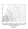
- Figure 5 can be reinterpreted to show the side view of a studio with the reflector now being the studio floor and the 2 m height of the antenna being due to a shoulder-mounted camera.
- the receiving antenna(s) be placed amongst the studio lights, which might be positioned at a height of around 3-4 m.
- the floor reflection causes very closely spaced contours of constant path difference at these heights and so here the vertical antenna separation required is very small.
- Figure 6 shows an example of the contours of constant path difference for a radio-camera being used at a sports stadium.
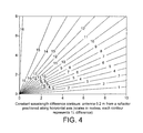
- the main difference between Figures 3 and 4 are the scale.
- Figure 4 should be interpreted as a side view, not a plan view.
- the reflector now represents the ground with the transmitter at 2 m height, i.e., on an operator's shoulder.
- the separation of the two transmitting antennas in this case needs to be about 1 cm to ensure that a null is turned into a peak for a receiving dish at a large horizontal distance away.
- the receiving site is 100 m away, that the first null appears at a height of about 40 cm (this can be determined by noting that the 100 ⁇ contour reaches a height of 80 m at a distance of 100 m).
- Operationally dishes tend to be placed high in a gantry just under the stadium roof, and so they are potentially vulnerable to multipath from the ground, but this analysis suggests keeping the receiving site close to the ground to eliminate multipath. However, this ignores multipath from the sides of the stadium and path blocking by people and other obstacles close to the ground.
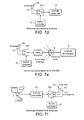
- Switching the RF signal alternately between a pair of antennas is simple to implement.
- the switch can be implemented at one of several points in the transmission chain as shown in Figures 7a to 7e.
- Figure 7a shows the switch 45a and its controller 47 inserted between the COFDM transmitter 40 and the antennas 49.
- Figure 7b shows the addition of extra radio frequency amplification 46 after the switch 45a to compensate for loss in the switch.
- Figure 7c shows the switch 45a at the output of the COFDM modulator 41 so that it switches the signal at baseband or intermediate frequency.
- the signals from the switch have to be separately upconverted and amplified 48.
- the receiving antennas can be switched as shown in Figure 7d where the switch 45a is placed between the receiving antennas 50 and the COFDM demodulator 10.
- Figure 7e shows the switch incorporated into one of the antennas in a system of the type described in British Patent Application No. 9725890.9, where the switch 45a is placed between two of the antennas 50 and one of the delays 12. In this situation some or all of the antennas could be switched. This switching could either be related to the frame structure of the signal multiplex or be free running. However, the former case may have a better error performance by switching at times suited to the error protection strategy used.
- the antenna spacing depends on the local environment and so should be adjustable in some way. Generally, the antennas need to be spaced both vertically and horizontally to account for reflections from surfaces at nearly every orientation.
- Figure 7f shows the implementation of a third antenna 51 and a three-way switch 45b that would be needed to deal with surfaces oriented along the axis between the first two antennas, but it may not be needed on a real situation because the field pattern is likely to be very complex anyway.
- both transmitting antennas may be producing a null at the receiving site and so switching between them just changes the field pattern from one null straight to another. Also the spectral harmonics produced by switching may be undesirable.
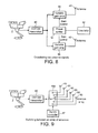
- An oscillator 52 provides a signal of the shape desired for the crossfade, such as a sine wave.
- a phase splitter 54 produces a plurality of versions of the crossfade signal with a known phase difference between them, which is given by the formula 360/n degrees, where n is the number of outputs of the phase splitter (two outputs are shown in Figure 8 which would therefore be 180 degrees out of phase with each other).
- the signal from the COFDM transmitter 40 is split to feed a variable gain amplifier 56 and antenna 49.
- the gain of each of the amplifiers 56 is controlled by one of the outputs of the phase splitter 54. This has two benefits:
- the gradual changeover between the transmitting antennas may help reduce the impact of phase jitter at the receiver, but it does not remove the situation of the RF field from both antennas producing nulls at the receiver at the same time. It is misleading to draw the analogy with stereo audio where an audio source can be made to appear at any position between a pair of loudspeakers just by changing the relative power levels from each loudspeaker. Basically, if each transmitting antenna separately produces a null at the receiving point due to multipath, then, by using superposition, the combined outputs of both antennas still produces a null.
- antenna elements separated by half the carrier wavelength or more will produce their own nulls (as in Young's two-slit experiment of optical interference); in many practical situations the required antenna spacing is many wavelengths.
- FIG. 9 A simple extension of the methods described above is shown in Figure 9 where an array of antenna elements 60 and then switch the RF signal progressively along the array using a multiple switch 45c to create the apparent movement of the transmitting source (analogous to some types of decorative illuminations, such as the light-pipe).
- This method makes the source emit from intermediate positions reducing the chance of jumping from one null to another. Making the antenna spacing less than a quarter of the carrier wavelength removes this chance completely.
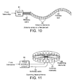
- FIG. 10 One practical implementation of such an array, shown in Figure 10, might be as a series of antenna patches 63 mounted along on a flexible belt 64 which could be wrapped round a radio-camera mast (or other suitable structure when remote cameras are mounted on vehicles, etc.).
- the exact shape of each patch would depend on various factors, such as beam width and polarisation.
- the effective antenna spacing can be changed by varying the number of radiating elements activated.
- the simplest form would be a linear array, but other shapes may prove beneficial.
- An extension of the switched array is to crossfade the RF power between the elements in an antenna array to avoid sudden phase changes. No extra interference nulls will be created in the RF field if the elements are separated by less than half the carrier wavelength.
- Figure 11 shows a circular multi-element transmitting array 67 supported on a ring 68 and fed like a phased array from a phase switching network 65 to emit a narrow beam which rotates round the antenna at a suitable rate, like the light beam from a lighthouse.
- multipath is reduced because illumination of the reflectors is greatly reduced when the beam is pointing to the receiver.
- the transmission time is small because the data must be sent when the beam is pointing to the receiver.
- All the antenna options above work without any feedback control, but they do require the antenna switching or crossfading rate and the spacing to be set up according to the environment in which it will be used. Since it is an operational requirement for the radio-camera to have a return video feed, then there is the opportunity to include a control channel to set the antenna switching rate and spacing in a feedback loop. Antenna "length" could be effectively changed in an antenna array by including or excluding elements at one end.
- a proposed sensing signal for the control loop is to look at the amplitude envelope of the signal to detect fluctuations caused by the reflections as shown in Figure 12.
- the received signal at the COFDM demodulator 10 could be applied in parallel to an envelope detector 70 and then split to feed a low-pass 71 and high-pass 72 filter pair with their transitions centred on the fluctuation rate of the RF field that the antenna switching is trying to achieve.
- the filter outputs would then be smoothed and used by the controller 73 for its decisions.
- a camera which switches transmission between two or more antennas can also be used to improve reception in systems employing a single receiver antenna and error protection for data.
Landscapes
- Engineering & Computer Science (AREA)
- Computer Networks & Wireless Communication (AREA)
- Signal Processing (AREA)
- Radio Transmission System (AREA)
- Mobile Radio Communication Systems (AREA)
Applications Claiming Priority (2)
| Application Number | Priority Date | Filing Date | Title |
|---|---|---|---|
| GB0104839 | 2001-02-27 | ||
| GB0104839A GB0104839D0 (en) | 2001-02-27 | 2001-02-27 | Digital radio communication system |
Publications (3)
| Publication Number | Publication Date |
|---|---|
| EP1239607A2 true EP1239607A2 (de) | 2002-09-11 |
| EP1239607A3 EP1239607A3 (de) | 2002-10-30 |
| EP1239607B1 EP1239607B1 (de) | 2006-11-22 |
Family
ID=9909621
Family Applications (1)
| Application Number | Title | Priority Date | Filing Date |
|---|---|---|---|
| EP02251355A Expired - Lifetime EP1239607B1 (de) | 2001-02-27 | 2002-02-27 | Digitales Funkkommunikationssystem |
Country Status (3)
| Country | Link |
|---|---|
| EP (1) | EP1239607B1 (de) |
| DE (1) | DE60216173T2 (de) |
| GB (2) | GB0104839D0 (de) |
Cited By (2)
| Publication number | Priority date | Publication date | Assignee | Title |
|---|---|---|---|---|
| WO2006099564A1 (en) * | 2005-03-15 | 2006-09-21 | Intel Corporation | Apparatus and method of detecting pilot carriers received on a fading channel |
| EP1556969A4 (de) * | 2002-10-31 | 2010-10-27 | Lg Electronics Inc | Verfahren zur auswahl einer senderantenne in einem funkkommunikationssystem |
Families Citing this family (1)
| Publication number | Priority date | Publication date | Assignee | Title |
|---|---|---|---|---|
| US7772449B2 (en) | 2007-08-01 | 2010-08-10 | Stone & Webster Process Technology, Inc. | Removal of acid gases and sulfur compounds from hydrocarbon gas streams in a caustic tower |
Family Cites Families (9)
| Publication number | Priority date | Publication date | Assignee | Title |
|---|---|---|---|---|
| US4604626A (en) * | 1983-11-21 | 1986-08-05 | Sanders Associates, Inc. | Acquisition system employing circular array |
| GB2196211B (en) * | 1986-09-12 | 1990-07-04 | British Broadcasting Corp | Communications system |
| JPH0338932A (ja) * | 1989-07-06 | 1991-02-20 | Oki Electric Ind Co Ltd | スペースダイバーシチ方式 |
| US5625881A (en) * | 1994-04-28 | 1997-04-29 | Bell-Northern Research Ltd. | Time and frequency diveristy in a radio system having intermittent operation receivers |
| GB2307375A (en) * | 1995-11-20 | 1997-05-21 | British Broadcasting Corp | Mobile Radio Communication System with Diversity Reception |
| US6026132A (en) * | 1997-09-29 | 2000-02-15 | Lucent Technologies, Inc. | Method and apparatus for mitigating the effects of rayleigh fading at low vehicle speeds |
| GB2332124B (en) * | 1997-12-05 | 2002-07-17 | British Broadcasting Corp | Digital radio communication system |
| US6317411B1 (en) * | 1999-02-22 | 2001-11-13 | Motorola, Inc. | Method and system for transmitting and receiving signals transmitted from an antenna array with transmit diversity techniques |
| EP1069706B1 (de) * | 1999-06-23 | 2016-10-05 | Texas Instruments Inc. | Funkkommunikationsgerät und -Verfahren mit einer steuerbaren Richtstrahlantenne |
-
2001
- 2001-02-27 GB GB0104839A patent/GB0104839D0/en not_active Ceased
-
2002
- 2002-02-27 EP EP02251355A patent/EP1239607B1/de not_active Expired - Lifetime
- 2002-02-27 DE DE2002616173 patent/DE60216173T2/de not_active Expired - Lifetime
- 2002-02-27 GB GB0204632A patent/GB2373970B/en not_active Expired - Fee Related
Cited By (2)
| Publication number | Priority date | Publication date | Assignee | Title |
|---|---|---|---|---|
| EP1556969A4 (de) * | 2002-10-31 | 2010-10-27 | Lg Electronics Inc | Verfahren zur auswahl einer senderantenne in einem funkkommunikationssystem |
| WO2006099564A1 (en) * | 2005-03-15 | 2006-09-21 | Intel Corporation | Apparatus and method of detecting pilot carriers received on a fading channel |
Also Published As
| Publication number | Publication date |
|---|---|
| EP1239607A3 (de) | 2002-10-30 |
| GB0104839D0 (en) | 2001-04-18 |
| GB2373970B (en) | 2004-07-07 |
| EP1239607B1 (de) | 2006-11-22 |
| DE60216173T2 (de) | 2007-09-13 |
| GB2373970A (en) | 2002-10-02 |
| DE60216173D1 (de) | 2007-01-04 |
| GB0204632D0 (en) | 2002-04-10 |
Similar Documents
| Publication | Publication Date | Title |
|---|---|---|
| RU2155460C2 (ru) | Антенна с широким лепестком диаграммы направленности | |
| US5949793A (en) | Transmission of digital and analog signals in the same band | |
| CA1333089C (en) | Low power multi-function cellular television system | |
| EP1229342A2 (de) | Signalerfassung unter Verwendung einer phasengesteuerten Gruppenantenne | |
| US6744823B1 (en) | Communication system between road and vehicle | |
| EP0851698B1 (de) | Drahtlose Kommunikationssysteme | |
| US9537211B2 (en) | Multi-feed diversity receive system and method | |
| KR20020070896A (ko) | 자동차에 사용하는 디지털 지상 및/또는 위성 무선 신호를수신하기 위한 다이버시티 장치 | |
| KR20000065190A (ko) | 통신을 개선하기 위한 방법 및 시스템 | |
| US20070222677A1 (en) | System and method for adjustingtransmission phasing in a point-to-point communication link | |
| EP1239607B1 (de) | Digitales Funkkommunikationssystem | |
| EP0921646B1 (de) | Digitales Funkkommunikationssystem mit Diversity-Empfang | |
| GB2397979A (en) | Simulating antenna movement to reduce interference | |
| EP1025619A1 (de) | Antenne zur wegesuche | |
| JP2002094445A (ja) | 路車間無線通信システム、アンテナシステム、および車両側無線通信装置 | |
| WO2002061970A1 (en) | Signal detection using a phased array antenna |
Legal Events
| Date | Code | Title | Description |
|---|---|---|---|
| PUAI | Public reference made under article 153(3) epc to a published international application that has entered the european phase |
Free format text: ORIGINAL CODE: 0009012 |
|
| AK | Designated contracting states |
Kind code of ref document: A2 Designated state(s): AT BE CH CY DE DK ES FI FR GB GR IE IT LI LU MC NL PT SE TR |
|
| AX | Request for extension of the european patent |
Free format text: AL;LT;LV;MK;RO;SI |
|
| PUAL | Search report despatched |
Free format text: ORIGINAL CODE: 0009013 |
|
| AK | Designated contracting states |
Kind code of ref document: A3 Designated state(s): AT BE CH CY DE DK ES FI FR GB GR IE IT LI LU MC NL PT SE TR |
|
| AX | Request for extension of the european patent |
Free format text: AL;LT;LV;MK;RO;SI |
|
| 17P | Request for examination filed |
Effective date: 20030422 |
|
| AKX | Designation fees paid |
Designated state(s): BE DE FR GB IT |
|
| 17Q | First examination report despatched |
Effective date: 20030730 |
|
| GRAP | Despatch of communication of intention to grant a patent |
Free format text: ORIGINAL CODE: EPIDOSNIGR1 |
|
| GRAS | Grant fee paid |
Free format text: ORIGINAL CODE: EPIDOSNIGR3 |
|
| GRAA | (expected) grant |
Free format text: ORIGINAL CODE: 0009210 |
|
| AK | Designated contracting states |
Kind code of ref document: B1 Designated state(s): BE DE FR GB IT |
|
| REG | Reference to a national code |
Ref country code: GB Ref legal event code: FG4D |
|
| REF | Corresponds to: |
Ref document number: 60216173 Country of ref document: DE Date of ref document: 20070104 Kind code of ref document: P |
|
| ET | Fr: translation filed | ||
| PLBE | No opposition filed within time limit |
Free format text: ORIGINAL CODE: 0009261 |
|
| STAA | Information on the status of an ep patent application or granted ep patent |
Free format text: STATUS: NO OPPOSITION FILED WITHIN TIME LIMIT |
|
| 26N | No opposition filed |
Effective date: 20070823 |
|
| PGFP | Annual fee paid to national office [announced via postgrant information from national office to epo] |
Ref country code: IT Payment date: 20120220 Year of fee payment: 11 |
|
| PGFP | Annual fee paid to national office [announced via postgrant information from national office to epo] |
Ref country code: DE Payment date: 20130220 Year of fee payment: 12 Ref country code: GB Payment date: 20130228 Year of fee payment: 12 Ref country code: FR Payment date: 20130301 Year of fee payment: 12 |
|
| PGFP | Annual fee paid to national office [announced via postgrant information from national office to epo] |
Ref country code: BE Payment date: 20130212 Year of fee payment: 12 |
|
| BERE | Be: lapsed |
Owner name: BRITISH BROADCASTING CORP. Effective date: 20140228 |
|
| REG | Reference to a national code |
Ref country code: DE Ref legal event code: R119 Ref document number: 60216173 Country of ref document: DE |
|
| GBPC | Gb: european patent ceased through non-payment of renewal fee |
Effective date: 20140227 |
|
| REG | Reference to a national code |
Ref country code: FR Ref legal event code: ST Effective date: 20141031 |
|
| REG | Reference to a national code |
Ref country code: DE Ref legal event code: R119 Ref document number: 60216173 Country of ref document: DE Effective date: 20140902 |
|
| PG25 | Lapsed in a contracting state [announced via postgrant information from national office to epo] |
Ref country code: DE Free format text: LAPSE BECAUSE OF NON-PAYMENT OF DUE FEES Effective date: 20140902 Ref country code: BE Free format text: LAPSE BECAUSE OF NON-PAYMENT OF DUE FEES Effective date: 20140228 Ref country code: FR Free format text: LAPSE BECAUSE OF NON-PAYMENT OF DUE FEES Effective date: 20140228 Ref country code: GB Free format text: LAPSE BECAUSE OF NON-PAYMENT OF DUE FEES Effective date: 20140227 |
|
| PG25 | Lapsed in a contracting state [announced via postgrant information from national office to epo] |
Ref country code: IT Free format text: LAPSE BECAUSE OF NON-PAYMENT OF DUE FEES Effective date: 20140227 |