EP1239901B1 - Drehmomentübertragendes führungselementsystem - Google Patents
Drehmomentübertragendes führungselementsystem Download PDFInfo
- Publication number
- EP1239901B1 EP1239901B1 EP00990348A EP00990348A EP1239901B1 EP 1239901 B1 EP1239901 B1 EP 1239901B1 EP 00990348 A EP00990348 A EP 00990348A EP 00990348 A EP00990348 A EP 00990348A EP 1239901 B1 EP1239901 B1 EP 1239901B1
- Authority
- EP
- European Patent Office
- Prior art keywords
- slots
- guidewire
- cuts
- slot
- axis
- Prior art date
- Legal status (The legal status is an assumption and is not a legal conclusion. Google has not performed a legal analysis and makes no representation as to the accuracy of the status listed.)
- Expired - Lifetime
Links
- 239000007787 solid Substances 0.000 claims abstract description 20
- 238000005520 cutting process Methods 0.000 claims abstract description 10
- 238000005452 bending Methods 0.000 claims description 40
- 238000000034 method Methods 0.000 claims description 24
- 210000003484 anatomy Anatomy 0.000 claims description 13
- 239000003550 marker Substances 0.000 claims description 11
- 229910001000 nickel titanium Inorganic materials 0.000 claims description 7
- 229910003460 diamond Inorganic materials 0.000 claims description 3
- 239000010432 diamond Substances 0.000 claims description 3
- 229920000642 polymer Polymers 0.000 claims description 2
- HLXZNVUGXRDIFK-UHFFFAOYSA-N nickel titanium Chemical compound [Ti].[Ti].[Ti].[Ti].[Ti].[Ti].[Ti].[Ti].[Ti].[Ti].[Ti].[Ni].[Ni].[Ni].[Ni].[Ni].[Ni].[Ni].[Ni].[Ni].[Ni].[Ni].[Ni].[Ni].[Ni] HLXZNVUGXRDIFK-UHFFFAOYSA-N 0.000 claims 1
- 210000005166 vasculature Anatomy 0.000 abstract description 9
- 230000008859 change Effects 0.000 abstract description 2
- 238000003698 laser cutting Methods 0.000 abstract description 2
- 238000010329 laser etching Methods 0.000 abstract 1
- 229910000679 solder Inorganic materials 0.000 description 15
- 230000007704 transition Effects 0.000 description 14
- 230000005540 biological transmission Effects 0.000 description 10
- 230000007423 decrease Effects 0.000 description 10
- 238000009826 distribution Methods 0.000 description 10
- 239000003292 glue Substances 0.000 description 10
- 239000000463 material Substances 0.000 description 10
- 229910001220 stainless steel Inorganic materials 0.000 description 10
- 230000008901 benefit Effects 0.000 description 8
- 238000004364 calculation method Methods 0.000 description 8
- 239000010935 stainless steel Substances 0.000 description 7
- 238000012360 testing method Methods 0.000 description 7
- 238000004519 manufacturing process Methods 0.000 description 6
- 238000005459 micromachining Methods 0.000 description 6
- BASFCYQUMIYNBI-UHFFFAOYSA-N platinum Chemical compound [Pt] BASFCYQUMIYNBI-UHFFFAOYSA-N 0.000 description 6
- 239000000853 adhesive Substances 0.000 description 5
- 230000001070 adhesive effect Effects 0.000 description 5
- 238000000576 coating method Methods 0.000 description 5
- 229910001260 Pt alloy Inorganic materials 0.000 description 4
- 238000013461 design Methods 0.000 description 4
- 238000005530 etching Methods 0.000 description 4
- 238000003754 machining Methods 0.000 description 4
- 230000008569 process Effects 0.000 description 4
- 238000007514 turning Methods 0.000 description 4
- 239000011248 coating agent Substances 0.000 description 3
- 239000002872 contrast media Substances 0.000 description 3
- 229940039231 contrast media Drugs 0.000 description 3
- 230000003247 decreasing effect Effects 0.000 description 3
- PCHJSUWPFVWCPO-UHFFFAOYSA-N gold Chemical compound [Au] PCHJSUWPFVWCPO-UHFFFAOYSA-N 0.000 description 3
- 239000010931 gold Substances 0.000 description 3
- 229920001477 hydrophilic polymer Polymers 0.000 description 3
- 229910052697 platinum Inorganic materials 0.000 description 3
- 238000000926 separation method Methods 0.000 description 3
- 238000005476 soldering Methods 0.000 description 3
- 238000012546 transfer Methods 0.000 description 3
- 229910001020 Au alloy Inorganic materials 0.000 description 2
- 229910052692 Dysprosium Inorganic materials 0.000 description 2
- KDLHZDBZIXYQEI-UHFFFAOYSA-N Palladium Chemical compound [Pd] KDLHZDBZIXYQEI-UHFFFAOYSA-N 0.000 description 2
- 238000013459 approach Methods 0.000 description 2
- 238000010276 construction Methods 0.000 description 2
- 238000012938 design process Methods 0.000 description 2
- KBQHZAAAGSGFKK-UHFFFAOYSA-N dysprosium atom Chemical compound [Dy] KBQHZAAAGSGFKK-UHFFFAOYSA-N 0.000 description 2
- 230000000694 effects Effects 0.000 description 2
- 238000002594 fluoroscopy Methods 0.000 description 2
- 229910052737 gold Inorganic materials 0.000 description 2
- 238000003384 imaging method Methods 0.000 description 2
- 238000005304 joining Methods 0.000 description 2
- 238000002595 magnetic resonance imaging Methods 0.000 description 2
- 238000012986 modification Methods 0.000 description 2
- 230000004048 modification Effects 0.000 description 2
- 238000005457 optimization Methods 0.000 description 2
- 238000004321 preservation Methods 0.000 description 2
- 238000012800 visualization Methods 0.000 description 2
- 229910001316 Ag alloy Inorganic materials 0.000 description 1
- 229910052688 Gadolinium Inorganic materials 0.000 description 1
- XUIMIQQOPSSXEZ-UHFFFAOYSA-N Silicon Chemical compound [Si] XUIMIQQOPSSXEZ-UHFFFAOYSA-N 0.000 description 1
- 239000002253 acid Substances 0.000 description 1
- 229910045601 alloy Inorganic materials 0.000 description 1
- 239000000956 alloy Substances 0.000 description 1
- 238000004458 analytical method Methods 0.000 description 1
- 238000002399 angioplasty Methods 0.000 description 1
- 238000000137 annealing Methods 0.000 description 1
- 230000004323 axial length Effects 0.000 description 1
- 239000008280 blood Substances 0.000 description 1
- 210000004369 blood Anatomy 0.000 description 1
- 150000001875 compounds Chemical class 0.000 description 1
- 238000002591 computed tomography Methods 0.000 description 1
- 230000008021 deposition Effects 0.000 description 1
- 238000010586 diagram Methods 0.000 description 1
- 230000003467 diminishing effect Effects 0.000 description 1
- 238000006073 displacement reaction Methods 0.000 description 1
- UIWYJDYFSGRHKR-UHFFFAOYSA-N gadolinium atom Chemical compound [Gd] UIWYJDYFSGRHKR-UHFFFAOYSA-N 0.000 description 1
- 239000003353 gold alloy Substances 0.000 description 1
- 230000006872 improvement Effects 0.000 description 1
- 208000014674 injury Diseases 0.000 description 1
- 230000007246 mechanism Effects 0.000 description 1
- 239000003921 oil Substances 0.000 description 1
- 229910052763 palladium Inorganic materials 0.000 description 1
- 230000002093 peripheral effect Effects 0.000 description 1
- 229920001296 polysiloxane Polymers 0.000 description 1
- 239000004810 polytetrafluoroethylene Substances 0.000 description 1
- 229920001343 polytetrafluoroethylene Polymers 0.000 description 1
- 230000002250 progressing effect Effects 0.000 description 1
- 230000002035 prolonged effect Effects 0.000 description 1
- 238000012552 review Methods 0.000 description 1
- 239000004065 semiconductor Substances 0.000 description 1
- 229910001285 shape-memory alloy Inorganic materials 0.000 description 1
- 229910052710 silicon Inorganic materials 0.000 description 1
- 239000010703 silicon Substances 0.000 description 1
- 239000004447 silicone coating Substances 0.000 description 1
- 239000004332 silver Substances 0.000 description 1
- 238000002560 therapeutic procedure Methods 0.000 description 1
- 230000008733 trauma Effects 0.000 description 1
- 230000000472 traumatic effect Effects 0.000 description 1
- 238000003466 welding Methods 0.000 description 1
Images


Classifications
-
- A—HUMAN NECESSITIES
- A61—MEDICAL OR VETERINARY SCIENCE; HYGIENE
- A61M—DEVICES FOR INTRODUCING MEDIA INTO, OR ONTO, THE BODY; DEVICES FOR TRANSDUCING BODY MEDIA OR FOR TAKING MEDIA FROM THE BODY; DEVICES FOR PRODUCING OR ENDING SLEEP OR STUPOR
- A61M25/00—Catheters; Hollow probes
- A61M25/0043—Catheters; Hollow probes characterised by structural features
- A61M25/0054—Catheters; Hollow probes characterised by structural features with regions for increasing flexibility
-
- A—HUMAN NECESSITIES
- A61—MEDICAL OR VETERINARY SCIENCE; HYGIENE
- A61M—DEVICES FOR INTRODUCING MEDIA INTO, OR ONTO, THE BODY; DEVICES FOR TRANSDUCING BODY MEDIA OR FOR TAKING MEDIA FROM THE BODY; DEVICES FOR PRODUCING OR ENDING SLEEP OR STUPOR
- A61M25/00—Catheters; Hollow probes
- A61M25/01—Introducing, guiding, advancing, emplacing or holding catheters
- A61M25/09—Guide wires
- A61M2025/09058—Basic structures of guide wires
- A61M2025/09083—Basic structures of guide wires having a coil around a core
-
- A—HUMAN NECESSITIES
- A61—MEDICAL OR VETERINARY SCIENCE; HYGIENE
- A61M—DEVICES FOR INTRODUCING MEDIA INTO, OR ONTO, THE BODY; DEVICES FOR TRANSDUCING BODY MEDIA OR FOR TAKING MEDIA FROM THE BODY; DEVICES FOR PRODUCING OR ENDING SLEEP OR STUPOR
- A61M25/00—Catheters; Hollow probes
- A61M25/01—Introducing, guiding, advancing, emplacing or holding catheters
- A61M25/09—Guide wires
- A61M2025/09175—Guide wires having specific characteristics at the distal tip
-
- A—HUMAN NECESSITIES
- A61—MEDICAL OR VETERINARY SCIENCE; HYGIENE
- A61M—DEVICES FOR INTRODUCING MEDIA INTO, OR ONTO, THE BODY; DEVICES FOR TRANSDUCING BODY MEDIA OR FOR TAKING MEDIA FROM THE BODY; DEVICES FOR PRODUCING OR ENDING SLEEP OR STUPOR
- A61M25/00—Catheters; Hollow probes
- A61M25/01—Introducing, guiding, advancing, emplacing or holding catheters
- A61M25/0105—Steering means as part of the catheter or advancing means; Markers for positioning
- A61M25/0133—Tip steering devices
- A61M25/0138—Tip steering devices having flexible regions as a result of weakened outer material, e.g. slots, slits, cuts, joints or coils
Definitions
- This invention relates to catheters and catheter guidewire apparatus and methods for making same. More specifically, the present invention relates to a guidewire apparatus with improved torque and flexure characteristics.
- Catheter guidewires have been used for many years to "lead” or “guide” catheters to target locations in animal and human anatomy. This is typically done via a body lumen, for example such as traversing Luminal spaces defined by the vasculature to the target location.
- the typical conventional guidewire is from about 135 centimeters to 195 centimeters in length, and is made from two primary components--a stainless steel core wire, and a platinum alloy coil spring.
- the core wire is tapered on the distal end to increase its flexibility.
- the coil spring is typically soldered to the core wire at a point where the inside diameter of the coil spring matches the outside diameter of the core wire.
- Platinum is selected for the coil spring because it provides radiopacity for better fluoroscopic or other radiologic imaging during navigation of the guidewire in the body, and it is biocompatible.
- the coil spring also provides softness for the tip of the guidewire to reduce the likelihood of unwanted puncture of a Luminal wall or the damaging of this and/or other anatomy.
- the guidewire is provided with a curved or otherwise tip that is curved or bent to a desired angle so as to deviate laterally a short distance. By rotation of the wire the tip can be made to deviate in a selected direction from an axis of the guidewire about which it rotates.
- the guidewire is inserted into a catheter so that the guidewire can be advanced so that its distal end protrudes out the distal end of the catheter, and also pulled back in a proximal direction so as to be retracted into the catheter.
- the catheter enables introduction of contrast media at the location of the distal tip to enable the visualization of a Luminal space being traversed by the catheter and guidewire. Visualization is by fluoroscope, for example, or another device.
- the guidewire and catheter are introduced into a Luminal space, comprising for example a vessel or duct and advanced therethrough until the guidewire tip reaches a desired Luminal branch.
- the catheter is advanced over the guidewire to follow, or track, the wire. This procedure is repeated as needed to guide the wire and overlying catheter to the desired target location.
- the catheter accordingly provides a means to introduce contrast media, and also provides additional support for the wire.
- the guidewire may be withdrawn, depending upon the therapy to be performed. Oftentimes, such as in the case of balloon angioplasty, the guidewire is left in place during the procedure and can be used to exchange catheters.
- a guidewire having a relatively low resistance to flexure yet relatively high torsional strength is most desirable.
- internal resistance from the typically numerous turns, and surface contact decreases the ability to advance the guidewire further within the Luminal space. This, in turn, may lead to a more difficult and prolonged procedure, or, more seriously, failure to access the desired anatomy and thus a failed procedure.
- a guidewire with high flexibility helps overcome the problems created by internal resistance.
- the guidewire does not also have good torque characteristics (torsional stiffness), the user will not be able to twist the proximal end in order to rotate the distal tip of the guidewire as required.
- a catheter guidewire apparatus in accordance with principles of the invention comprises a thin elongate body of material having an longitudinal axis, and which is formed so as to define at a distal portion a configuration comprising a plurality of integrally formed beams disposed along the length of the body.
- the integral beams extend axially and transversely of the body and are positioned and formed to give the guidewire flexibility while maintaining a relatively high degree of torsional stiffness.
- transverse and axial beams adjacent one to another are configured so that the strain (deformation) in the adjacent axial and transverse beams as defined above is as nearly as possible equal in magnitude when the guidewire is subjected to torsional and bending forces resulting from twisting and bending of the apparatus.
- These beams comprise the portions of the wall of a tubular body, or the outer portions adjacent the outer surface of a solid body member, which remain after cuts are machined into the body.
- the beams can be formed between cuts, by making cuts in pairs substantially opposite from one another and substantially parallel to each other.
- the spacing and depth of the cuts comprising the cut pairs being adapted to provide desired maximum flexibility while sacrificing minimal torsional strength.
- the guidewire 200 includes a proximal end 204 a distal end 208, and a midportion 210 disposed therebetween, with the proximal end being mounted in a conventional pin vise type torquing chuck 212.
- the guidewire 200 is preferably constructed of nickel titanium alloy, and may range in size from about 0,2 mm (.008 inches) to about 2,25 mm (.090 inches) in diameter and from about 135 to 300 centimeters in length.
- the guidewire 200 could also be made of stainless steel. Four preferred diameter sizes are 0,2 mm (.008 inches), 0,35 mm (.014 inches), 0,4 mm (.016 inches) and 0,875 mm (.035 inches).
- Cuts, slots, gaps or openings 216 and 220 are formed in the guidewire 200 along the length thereof, including the midportion 210, either by saw cutting (e.g., diamond grit embedded semiconductor dicing blade), etching (for example using the etching process described in U.S. Patent No. 5,106,455 ), laser cutting, or electron discharge machining. Cuts 216 are angled to allow for a longer cut and thus greater flexibility, whereas cuts 220 are generally perpendicular to the long dimension of the guidewire.
- saw cutting e.g., diamond grit embedded semiconductor dicing blade
- etching for example using the etching process described in U.S. Patent No. 5,106,455
- laser cutting or electron discharge machining.
- the cuts are specifically configured to form transverse beams within the body of the guidewire. This configuration allows the cuts and beams to interact to provide for lateral flexibility in the guidewire, while maintaining torsional stiffness.
- the flexure profile and torsional stiffness of the guidewire may be selectively and relatively independently modified. Generally, the more closely spaced the cuts and the greater their depth, the more flexible will be the guidewire. However, modification of the exact shape, orientation, and spacing of the cuts will also allow selective modification or preservation of the torsional characteristics of the cross section independent of flexibility.
- the distal end 208 of the guidewire 200 may be preshaped with a curve, as shown, to allow for directing the guidewire around curves and bends. To maintain flexibility in the distal end 208, cuts may also be provided on that end. Advantageously, the tip is rounded to minimize the chance of traumatic piercing of body tissue. Also formed on the distal end 208 is a radiopaque marker or band 224.
- the band 224 may be gold or platinum alloy (for X-ray fluoroscopy) or gadolinium or dysprosium, or compounds thereof (for MRI) and may be formed on the distal end 208 by deposition, wrapping or use of shape memory alloy (NiTi) effect to "lock" the band around the end.
- FIG. 2 is a side, fragmented view of a guidewire 230, showing three alternative type cuts 234, 238 and 240.
- These type cuts provide a kind of built in flexure stop to prevent further flexure of the guidewire when the cut openings close to contact one another and prevent further flexure in that direction.
- Wedge shaped cuts 234 may be formed on opposite sides of the guidewire 230, with the greater width of the wedge being at the bottom of the cut.
- T-shaped cuts 238 may likewise be formed on opposite sides of the guidewire 230, with the cross piece of the T being at the bottom of the cut.
- Cuts 240 are generally circular as shown. It will be apparent that other cut shapes could also be provided to meet the needs of the user.
- the cuts 234, 238, and 240 are shown oppositely oriented, but it will be apparent that the cuts could also be formed at circumferentially-spaced locations about the guidewire, or a alternating locations such as shown and described in more detail with regard to, for example, FIG. 5.
- All three types of cuts shown in FIG. 2 form an integral transverse beam section, shown in cross-hatch as areas 232, 236, and 242, respectively, between oppositely disposed cuts.
- This configuration provides at least two distinct benefits. First, it allows the beam section to be longer than the gap of the flexure stop. This allows the amount of strain in the beam prior to stop engagement to be controlled by varying the ratio of beam length to gap size, allowing more flexibility, i.e. less bending resistance.
- torsional strength is primarily provided by the outer portion of the cross section of a member.
- a relatively thin-walled pipe will have nearly the same torsional strength as a solid bar of the same diameter because the central portion of the cross section of the solid bar contributes very little to torsional strength.
- the beam sections 232, 236, or 242 include a significant amount of the outer portion of the cross section of the guidewire, and therefore transmit varying proportions of the torsional forces from one side to the other of the cuts 234, 238, and 240 depending on their shape.
- beam 232 is relatively long (measured in the direction of the long axis of the guidewire), but is relatively deep (measured transverse to the long axis) and will therefore transmit a relatively large amount of torsional force.
- Beam 236 is longer and thinner than beam 232, and will therefore transmit a smaller amount of torsional force across the cut 238.
- beam 240 is the shortest and strongest of all, and will probably transmit the greatest amount of torsional force. However, given the size and shape of cuts 240, this configuration may provide the greatest flexibility.
- the flexibility of the guidewire section may be selectively altered without affecting the size or strength of the torsion beam section.
- the flexibility and torsional strength of the guidewire may be selectively and relatively independently altered.
- longitudinally adjacent pairs of cuts may be rotated about 90 degrees around the wire from one another to provide flexure laterally and vertically.
- the cuts may be located to provide preferential flexure in only one, two, three, etc. directions, if that is desired.
- the cuts could be randomly formed to allow bending (flex) equally, non-preferentially in all directions or planes. This could be achieved by circumferentially spacing the cuts.
- FIG. 3 shows an alternative embodiment for applying a radiopaque marker to the distal end of a guidewire 244, shown in side, fragmented view.
- An annular trough or channel 248 is formed at the tip of the guidewire 244, and a radiopaque wire coil, preferably made of platinum alloy, is wound about the guidewire in the channel.
- the coil 252 could be welded or soldered to itself to hold it in place at the tip of the guidewire 244.
- the guidewire could be cooled and deformed to allow the coil to be placed on the wire and then when the guidewire were returned to room temperature, the coil would be maintained in place on the guidewire without the need for welding or soldering or other joining mechanism, except for joining the coil to itself.
- FIG. 4 is a side, fragmented view of a solid guidewire 260 formed with opposing cuts 264 spaced along a portion of the guidewire, and opposed cuts 266 rotated 90 degrees from opposed cuts 268.
- the rotated cuts 268 are preferably arranged in opposing pairs, with opposite cut corresponding to 268 not visible on the far side of the guidewire.
- the cuts could be formed to provide preferential bending (flex) in one plane, or could be positioned to allow bending in multiple planes. This could be achieved, for example, by rotating adjacent pairs of cuts by 45 degrees with respect to one another or some other selected angular amount.
- the transverse beam sections 262 between adjacent opposing cuts 264 are shaded in FIG. 4 . It will be apparent that the pairs of rotated cuts 268 will also form transverse beams therebetween, except that these beams will be oriented at an angle of 90 degrees relative to the beam between cuts 266.
- FIG. 5 is a side, fragmented view of a solid guidewire 270 formed with staggered or offset cuts 274 on opposite sides of the guidewire.
- a curved distal end 278 is also shown with a radiopaque marker band 280.
- certain pairs of offset cuts could be rotated with respect to the other pairs, to thereby control direction of flexure.
- This configuration also presents particular advantages regarding torsional control.
- opposed cuts produce thin flexure beams 262 between the bottoms of each pair of opposed cuts. The dimensions and flexure properties of these beams are determined by the depth, separation and width of the cuts and so the flexibility of a guidewire with opposed cuts may be controlled by varying these parameters.
- Offset cuts as indicated in FIG. 5, produce much larger flexure beams 272 in the area between each pair of adjacent cuts. As will be expected, these large beams are able to transmit a relatively large amount of torsion.
- this section will also comprise relatively thin flexure beams 276 between the base of each cut and the opposing side of the guidewire. While these beams 276 are relatively thin, they will nevertheless transmit a relatively large amount of torsion because they are located toward the outside of the cross section.
- the flexure properties of this guidewire are determined not only by the depth and width of the cuts (as with opposed cuts) but also by the offset (axial spacing) of the cuts. Consequently, the flexibility of a guidewire with offset cuts can be more accurately controlled by varying any or all of these parameters. Also, the flexibility could be varied simply by controlling the degree of the offset while keeping the depth and width of the cuts constant. More importantly, however, the torsional strength of the guidewire can be maintained because the beam sections which primarily resist torsional force are more fully preserved with offset cuts.
- Offset cuts provide additional advantages because it is more practical to produce a consistent pattern of this type of cut than with opposed cuts.
- Very flexible sections with opposed cuts require very deep and/or wide cuts, and controlling either parameter may be problematic since very deep cuts could overly weaken the guidewire and very wide cuts may result in catching on and/or damaging tissue through which the guidewire is threaded.
- Very flexible beams using the offset cut pattern may be produced without the need for either deep or wide cuts, but rather by simply varying the distance or separation of the offset cuts, and this may be done very accurately.
- FIG. 6 is a side, fragmented view of a solid guidewire 284 having an enlarged proximal section 288, which provides more torquability, and a narrowed distal section 292, covered by a hydrophilic polymer sleeve 294.
- the enlarged section could be 0,35 mm (.014 inches) in diameter whereas the narrowed section could be 0,25 mm (.010 inches) in diameter.
- the distal end 296 of the guidewire 284 is formed with cuts as earlier described. Of course, cuts could also be provided at other locations in the narrowed section 292 or in the enlarged section 288, to increase flexibility, while maintaining high torsional stiffness.
- FIG. 7 is a side, fragmented view of a solid guidewire 300 having a tapered distal end 304 about which is wrapped a coil 308 made, for example, of platinum alloy. Disposed at the tip of the distal end 304 of the guidewire and in the end of the coil 308 is a solder ball 312. Cuts 316 may also be formed in the guidewire 300 as discussed earlier.
- nickel titanium alloy guidewires can be heat treated to vary the flexure characteristics. For example, selective annealing along the length of the wire can change stress/strain relationship of the material, and thus the flexure.
- the guidewires can be made “flow directable” by providing highly flexible distal ends.
- Flow directability means that the distal end of the guidewire tends to "flow” with the blood around curves and bends in a vasculature passageway.
- the surface of the guidewire may be electropolished to increase the smoothness thereof, and additionally, a lubricious coating may be applied to the surface of the guidewire such coatings might illustratively include silicone based oil and/or polymer or hydrophilic polymers.
- a lubricious sleeve made, for example, of a hydrophilic polymer could also be provided for disposal over the guidewire.
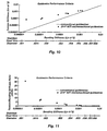
- Figures 8-11 provide graphical evidence of the improvement this invention provides over the prior art. These graphs depict actual test results of catheter guidewires formed according to this invention, showing the strength of the inventor's catheter guidewires compared to the prior art, and the relative preservation of torsional strength relative to flexibility.
- the prior art does include catheter guidewires with cuts or notches formed therein to increase flexibility of the distal end of the catheter. However, these cuts are not formed so as to simultaneously preserve the torsional strength of the guidewire. With these prior art catheter guidewires, the distal end becomes very flexible, but has very poor torsion transmission characteristics. The result is that the end of the guidewire flops around, but cannot easily be turned or rotated within a catheter or vessel.
- FIG. 8 is a graph of guidewire tensile strength compared to bending stiffness for the micromachined guidewire of the present invention.
- the individual (square) data points represent tension test results for micromachined guidewires.
- the ultimate tensile strength in pounds is indicated on the vertical axis, while the bending stiffness in psi is given on the horizontal axis.
- Below the horizontal axis is a second axis noting the size of stainless steel wire which would correspond to the respective bending stiffness shown in the horizontal axis.
- the solid line represents the theoretical tensile strength for equivalent solid wires.
- FIG. 9 is a graph of the ultimate torsional strength of the micromachined guidewire of the present invention compared to its bending stiffness.
- the vertical axis shows the ultimate torsional strength of the guidewire in units of pound-inches, and the horizontal axis shows the bending stiffness in psi.
- the square data points represent actual test results of micromachined catheter guidewires, and the solid line represents the theoretical results for a catheter guidewire of solid circular cross section. It will be apparent from this graph that as the bending stiffness (or size) of the guidewire decreases, the expected or theoretical torsional strength also decreases. This is depicted by the solid line.
- FIG. 11 is a graph showing the ratio of torsional stiffness to bending stiffness of the micromachined guidewire of the present invention compared to its bending stiffness.
- the vertical axis represents a ratio of torsional stiffness to bending stiffness (JG/EI), with the result that the expected relationship of bending stiffness to torsional stiffness (the solid line) is now a horizontal line.
- this line is set equal to unity, in order to more graphically show the actual results of the inventors' tests.
- the torsional strength of the micromachined guidewires was more than 30 times more than expected.
- the condition indicated by FIG. 11 represents some unexpected results.
- the goal was primarily to increase the flexibility.
- the inventors noticed a corresponding (and expected) decrease in torsional strength. This is a significant problem with catheter guidewires because guidewires with low torsional strength cannot be manipulated as easily, and are more likely to become wedged or jammed into the catheter or vasculature of the patient.
- a torsionally weak guidewire when the user twists the proximal end, there is a significant delay in the transmission of the torque to the distal end.
- FIG. 12 shows cross-sectional views of guidewires disposed within the lumen of circular and elliptical catheters.
- a circular catheter is advanced into the vasculature of a patient and navigates curves and other tortuous routes, the cross-sectional shape of the catheter frequently tends to flatten out in places into a more elliptical cross-section.
- a guidewire 400 is disposed in catheter 402 having a circular cross-section, it would have no preference as to its location within the cross section -- its position will present a state of physical equilibrium regardless of its location because all locations are the same.
- the guidewire 400 in a central location represents a state of unstable equilibrium, like a ball sitting on the top of another ball.
- the result is that the guidewire will naturally gravitate to a point of stable equilibrium 406, in the tight corner of the catheter lumen.
- the area of contact between the guidewire and the catheter is much larger, resulting in large frictional forces which will hinder the easy movement of the guidewire within the catheter.
- FIG. 13 shows the potential serpentine path of a torqued guidewire 420 through a catheter 422.
- a guidewire 500 in accordance with principles of the invention comprises a proximal portion 502 extending from a proximal end 504 to a first transition portion 506 where the diameter of the guidewire changes.
- This proximal portion comprised a stainless steel core wire 501 configured as solid wire of circular cross section.
- the core wire in the proximal portion is covered with a low friction coating.
- PTFE is used to coat the proximal portion in the illustrated example.
- the proximal portion has a diameter as large as needed to transmit torque sufficient for the intended use of the guidewire.
- a diameter of about 14 thousandths of an inch is appropriate, and is used in the illustrated example.
- the stainless steel wire is ground to a smaller diameter, transitioning over an axial length sufficient to provide a smooth transition. This is about 50 mm (2 inches) in one embodiment.
- the guidewire 500 has a more complex configuration.
- a proximal coil 508 is disposed over the stainless core wire 501.
- the core wire continues to the distal end 510 of the guidewire, the proximal coil overlaying the core wire as will be further explained.
- the proximal coil is attached to the core wire at the first transition portion 506 by a proximal solder joint 512 at a point where the inner diameter of the coil matches the outer diameter of the core wire.
- the diameter of the core wire continues to decrease under the proximal coil, and beyond it in accordance with a grind profile that will be described.
- the guidewire 500 in an exterior aspect comprises a micro machined tubing 514 formed of a superelastic material such as NiTi alloy.
- This micromachined tubing is very important to functionality of the catheter guidewire, as it transmits torque to the distal end 510 of the guidewire but is very flexible.
- the micromachined tubing overlays additional structure as will be described below.
- the micromachined tubing is attached to the proximal coil 508 via other underlying structure, and the core wire 501 at a medial solder and glue joint 516. The location of this joint is important as it is the point where the torsional force "carrying capacity" of the core wire 501 is substantially equal to that of the micromachined tubing.
- a force path is therefore established which extends through the core wire from the proximal end 504 of the guidewire 500 to the medial solder and glue joint 516, then continues through the micromachined tubing 514 to the distal end 510 of the guidewire 500.
- the outer diameter of the proximal coil 508 is substantially the same as the proximal portion 502 of the core wire.
- the outer diameter of the micromachined tubing 514 at the distal tip portion 511 of the guidewire 500 is also approximately the same, all being about 14 thousandths of an inch.
- the proximal coil is about 225 mm (11 inches) long and the distal tip portion comprising the micromachined tubing is about 50 mm (2 inches) long.
- the distal tip portion can be given a curved or other bent configuration is known in the art.
- the micromachined tubing, underlying structure (not shown), and the core wire 501 are attached at a distal solder and glue joint 518.
- the core wire has a very small diameter at the distal end, the grind profile reducing it to approximately 2 thousandths of an inch prior to reaching that point.
- the distal solder and glue joint comprises an adhesive 520 which is formed into a rounded configuration at the distal end of the guidewire to form an atramatic tip.
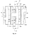
- FIGs. 14-18 the construction of an exemplary guidewire configuration will be described in more detail.
- the core wire 501 alone is seen to advantage, with the grind profile appreciable.
- the corewire has a rounded configuration at the proximal end 504 of the wire, and the proximal portion 502 is as previously described, and is about 1625 mm (65 inches) in length in one exemplary embodiment.
- the grind profile extends about 350 mm (14 inches) further to the distal end 510 of the guidewire 500.
- a second 522 and a third 524 transition portion are provided.
- the core wire has a first reduced diameter portion 526 having a length of about 150 mm (6 inches) and a diameter of about seven and a half thousandths of an inch.
- the second transition portion is also about 2 inches in length, and the diameter further reduces from that of the first reduced diameter portion to about five and a half thousandths of an inch. This diameter is maintained for about 62 mm (two and a half inches), to form a second reduced diameter portion 528.
- the diameter further decreases to about two thousands of an inch, which is maintained to the distal end 510 as mentioned, to form a third reduced diameter portion 530.
- This third transition portion is about 2,5 mm (one tenth of an inch in length), and the third reduced diameter portion is about 2,5 and 22,5 mm (one and nine tenths inches) in length in the illustrated exemplary embodiment.
- the third reduced diameter portion is configured to be extremely flexible as will be appreciated, but retain sufficient axial strength to help prevent distal tip separation on withdrawal of the guidewire from a position where the tip may be stuck in the anatomy, and to assist in facilitating pushability of the distal tip portion 511 of the guidewire.
- a medial coil 532 is attached to the core wire 501 at the third transition portion 524.
- the medial coil has an outer diameter substantially equal to the inner diameter of the proximal coil 508 and the inner diameter of the micromachined tubing 514. It is attached by soldering, and this location of attachment on the third transition portion is that of the medial solder and glue joint mentioned above. Also, it will be noted that the location is near the proximal end of the third transition portion, so that the diameter of the core wire at this location is substantially the same as the second reduced diameter portion 528.
- the location on the grind profile is important as it represents the "end of the line" for torque transmission through the core wire, and the diameter of the corewire is directly proportional to the amount of torsional force that can be transmitted, the location and diameter are chosen in conjunction with selection of the parameters of the micromachined tubing so that the "carrying capacity" for torque is substantially equal.
- a mis-match represents an inefficiency in this regard and is to be avoided unless for some design objective a discontinuity in torquability is desired at this point.
- the medial coil 532 is formed of stainless steel in one embodiment, and has a proximal unwound portion 534 at its proximal end, to aid in more secure bonding to the core wire 501 as a longer length of coil wire can be bonded due to slight deformation thereby allowed to follow the grind profile.
- the medial coil has a distal unwound portion 536 which will be further described next.
- a distal coil 538 is disposed over the third reduced diameter portion at the distal tip portion.
- the proximal end of the distal coil is provided with an unwound portion 540 which cooperates with the distal unwound portion 536 of the medial coil to form a secure interlock by intertwining of the coils, then soldering.
- the distal coil can be of slightly larger diameter wire, due to the reduced grind profile it overlays, but the outside diameter is held to be slightly less than that of the inside diameter of the micromachined tubing (not shown) as will be described.
- the distal coil is formed of a radiopaque material in the illustrated embodiment to provide enhanced fluoroscopic visibility.
- the distal coil thus acts as a marker to aid in navigation of the guidewire within the anatomy of a patient.
- the drawing figures are not to scale, and the distal coil can be considerably longer than the medial coil 532.
- the distal end of the distal coil is soldered to the core wire 501 adjacent the distal end 510 at the location of the distal solder and glue joint 518.
- the guidewire 500 apparatus is assembled by attaching the medial spring 532 to the core wire, then attaching the distal (marker) coil 538 to the medial coil, then the proximal coil is slipped over the assembly and soldered to the core wire 501 at the proximal solder joint 512 and to the medial coil 532 at the location of the medial solder and glue joint 516.
- the solder used throughout is a silver or gold alloy solder or another material regulatory-approved for such use.
- fabrication of the catheter is completed by placement of the micromachined tubing 514 over the distal tip portion 511. It is fixed in place by securing it at its proximal end at the medial solder and glue joint 516 by means of a suitable adhesive such as a UV cured regulatory-approved adhesive such as Dymax, and by attaching the distal end to the distal tip of the core wire 501, and also to the distal (marker) coil by an identical or similar adhesive.
- a suitable adhesive such as a UV cured regulatory-approved adhesive such as Dymax
- this adhesive when cured forms a rounded tip 520 to reduce trauma, and completes the distal solder and glue joint which holds together the core wire, distal marker coil, and the micromachined tubing at the distal end 510 of the guidewire.
- the guidewire can further include a micromachined "barcode" identification 142 located at a convenient location such as adjacent the proximal or distal end of the guidewire.
- the barcode is made by very lightly scoring the surface to form a binary code to encode identifying information regarding the catheter. This is done by a similar process to that used to micromachine the tubing 514 or another guidewire as discussed above and as follows.
- the advantage of such a marking system is that individual guidewires can be identified, enabling "lot of one"custom manufacturing and marking of one to as many as desired guidewires 500.
- FIG. 19 discussion of the micromachined tubing 514 more specifically should include mention of how the tubing is made.
- FIG. 19 discussion of the micromachined tubing 514 more specifically should include mention of how the tubing is made.
- further details regarding fabrication of the tubing can be found in copending U.S. patent application serial no. , Attorney Docket No. T3681CIP1, the disclosure of which is hereby incorporated herein by reference.
- a unique construction combined with optimization provides increased torquability while allowing flexure, so as to be compliant with tortuous vasculature in accessing a target site within the patient's anatomy.
- the present invention is directed to maximizing torque transmission, while minimizing resistance to bending of a guidewire body, for example in the tubular member 514 shown.
- a tubular structure is implicated, even though a solid member may be used. Therefore the following discussion will apply to solid wires as well, though it will be understood that this is because an assumption is made that the inner portion of the wire is not contributing appreciably, and the structure other than a tubular portion of it is being ignored.
- a tubular configuration is advantageous as other structure can be placed inside, as in the case of the illustrated embodiment given by example herein employing a tubular micromachined tubing segment 514 at a distal tip portion 511.
- One way in which the guidewire distal tip portion is optimized is using superelastic material, preferably formed as a tube, micromachining the tube to create a structure which maximizes torque transmission while minimizing resistance to bending.
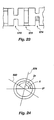
- a section of micromachined tubing 514, having slot-like cuts formed therein is shown to illustrate the structure.
- the cuts are opposed cuts in the illustrated embodiment. That is, two cuts are made from opposite sides of the tubing at the same location along the longitudinal axis of the tubing. The depth of the cuts is controlled to leave a segment 546 of the tubing wall extant between the cuts on each of the opposite sides (180 degrees apart) of the tubing.
- segments will acts as “beams” as discussed above to carry forces across the cut area at that location along the longitudinal axis 548 of the tubing.
- axial beams As a matter of convention such segments will be referred to as "axial beams” 546 as they carry or transfer forces in roughly an axial direction from adjacent structure on one side to adjacent structure on an opposite side.
- a pair of opposed cuts 550 is made adjacent to the cuts previously described (544) the location of the cuts is made such that the axial beam(s) 546A formed by the second set of cuts is displaced circumferentially from the adjacent axial beam(s) 546. This of course is done by rotation of the tube relative to the saw used to cut the tubing through some angle before cutting. This can be seen in FIG. 20.
- transverse beams 552 are created.
- the transverse beams 552 are defined as the curved portion of the tubing wall between adjacent cuts 544, 550 and adjacent axial beams. e.g. 546 and 546A. As will be appreciated, these transverse beams carry forces from a particular set of axial beams to the two adjacent axial beams created by the adjacent set of cuts.
- this matching can be done in tubing of constant cross section by variation of several parameters, namely the location (spacing 555 between), width 556, and depth 558 of cuts (e.g. 544. 550) made. Wider spacing of cuts creates wider transverse beams, shallower cuts create wider axial beams. Likewise more closely spaced cuts create narrower transverse beams, and deeper cuts create more narrow axial beams. Wider cuts create longer axial beams.
- the configuration of the micromachined tubing is defined by calculation, using well-known formulas for stress and stress/strain.
- the design process can further include finite-element analysis of the configuration to give localized stress and strain values. The calculations are repeated as necessary using incrementally changing parameters to optimize the design taking into account the concepts set forth herein.
- a saw blade of a specified width will be used. And accordingly the width of all cuts is held to this value.
- a diamond silicon wafer cutting saw blade (as is used in the microprocessor and memory chip manufacturing art- not shown) about one thousandth of an inch wide is used to make the cuts (e.g. 544). While it is possible to make wider cuts by making a first cut, then moving the wire relative to the blade by a distance up to a width of the blade, and repeating as necessary for wider cuts, speed of fabrication is higher if a single cut is used. Therefore, using this constant cut width, the possible variables are depth 558 of cut and spacing 555.
- cut width 556 is to be held constant, in one embodiment the other parameters are selected as follows.
- the bending stiffness desired at any selected location along a length of tubing is obtained by selection of an appropriate spacing 555 between cuts.
- selection of a distance between the set of opposed cuts to be made (e.g. 546A) and the last set of opposed cuts made (e.g. 546) will define, by means of the calculations, the depth of the cuts to be made as the distance between cuts defines the width of the transverse beams, and the width of the transverse beams is related to the width of the axial beam by the condition of equality of strain values to be obtained for a given applied torsional force 554 as mentioned.
- the locations of the axial beams 546 will be set by the relative angular displacement of the adjacent sets of opposed cuts, as will be described, and hence the width and the length of the transverse beams 552 will be known.
- the width of the axial beams to be created depends on the depth of cut.
- the length of each axial beam is the same and equal to the constant cut width (e.g. one thousandth of an inch in the illustrated embodiment).
- the depth of cut is determined by comparison of the strain in the each of the resulting axial beams (they are assumed to be the same, though in fact they may not be in all cases due to differing force distribution due to variations in geometry) and then matching the strain in the axial beam(s) (e.g. 546) with the strain in the transverse beam(s) (e.g.
- transverse beams are created between each set of opposed cuts.
- the resulting strains are evaluated in each of the four beams, but in one embodiment another simplifying assumption is made that the strain in the two shorter transverse beams is the same, and likewise the strain in the two longer transverse beams is the same.
- the greater of the resulting strains in the transverse beams is compared with the strain in the axial beams. This represents the force transmission path for transfer of the torque.
- the depth of cut 558 is varied until the strains are matched. This value is then used in making the cuts at that location.
- axial and transverse beams there is a practical limit on the size of axial and transverse beams. Too large at the desired advantages are lost, too small and imperfections in materials and variations within the tolerances in machining can compromise performance. This may be governed by the thickness of the tubing if tubing is used, the size of the saw blade, accuracy of the machining apparatus, etc. Generally speaking, axial or transverse beams having dimensions on a par with or smaller than the width of the cutting blade used to micromachine them are avoided.
- the design process then, in summary, is in one embodiment to space the cuts (e.g. 544, 550) apart along the axis 548 of the tubing so as to provide bending as desired.
- the cuts will be closer together to give less resistance to bending, and more spaced apart to give more resistance to bending. (See, for example FIGs. 13 and 18, where the tubing segment 514 becomes more flexible toward the distal end 510 of the guidewire 500.)
- the stiffness can be controlled by means of variation of the spacing 555 of the cuts, the other parameters being selected as appropriate as described above.
- the bending stiffness of the tubing can vary along the longitudinal axis, for example being made to gradually become less stiff toward the distal end, by gradually decreasing the spacing between cuts as in the above example.
- the depth 558 of the cuts is calculated using stress/strain relationships to match the strain in the axial 546 and transverse 552 beams created.
- the strain in the axial beams is matched to that of the greatest calculated in the previously calculated transverse beams.
- another method could be employed, for example comparing the strain in a given axial beam 546A to that of the transverse beams 552, 552A on either side of the axial beam along the axis 548 of the tubing 514 to match the strain.
- the average of the highest strain values in transverse beams 552, 552A1, 552A2 (552A1 and 552A2 being of unequal length the strains may be markedly different), on either side can be used to match the strain in the axial beam546A under consideration.
- varying the thickness of the axial beam(s) affects the forces transmitted to the transverse beams and therefore varies the stress and strain in the transverse beam; so, as a result, many iterations of these calculation steps can be required to optimize the design.
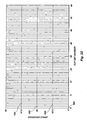
- the object is to provide a distribution of cut orientations along the length of the tubing that minimizes "preferred" bending directions of the micromachined tubing 514 giving rise to undesirable effects collectively referred to as "whip” or a deviation of expected rotational result at the distal tip of the guidewire from that expected by the user from rotational inputs made at the proximal end of the guidewire by turning the collet fixture 212.
- one way of organizing the cut distribution to minimize whip is to assume a first cut pair of opposed cuts (180 degrees apart) and a second pair of opposed cuts immediately adjacent will be offset by an angle of ninety degrees. Collectively the four cuts will be referred to as a first cut set 560. A second cut set 562 of adjacent opposed cuts oriented ninety degrees apart is subsequently made, these being oriented with respect to the first cut set (designated arbitrarily as oriented at 0 degrees) so as to be rotated 45 degrees. The next similar cut set 564 is oriented at 22.5 degrees, and the next at 67.5 degrees, and so on in accordance with the distribution graphically illustrated in the figure. The sequence repeats every 64 cut sets (128 opposed cuts, and 256 cuts in total).
- the cut distribution is defined by a helical pattern.
- a first cut pair 570 is at zero degrees.
- a second cut pair 572 is rotated with respect to the first through a chosen angle "x". For example, this angle can be 85 degrees.
- a third cut pair 574 is oriented by rotation through an angle equal to 2x, or 170 degree in the exemplary embodiment. This pattern is continued, as the next cut pair (not shown) is oriented at 3x or 255 degrees, etc. continuing to turn in the same direction and by the same magnitude of angular rotation, x.
- the bending axis 576 formed by the first cut pair 570 is oriented at 0 degrees; and the next bending axis 578 formed by the second cut pair is oriented at 85 degrees in the example, and the third bending axis 580 at 170 degrees, and so on.
- the pattern will repeat after 72 cut pairs (144 total cuts) in the illustrated example where x is equal to 85 degrees.
- the medial solder/glue joint (516 in the FIGs.) is located is substantially at the point where the grind profile drops to about 0,125 mm (.005 inch) diameter.
- the NiTi tubing segment which has been micromachined as described above provides a superior path for transmission of torque to the distal tip 510 of the guidewire from that point while at the same time facilitating bending.
- the exemplary embodiment illustrates that the guidewire configuration can be optimized for cost as well, the less expensive stainless steel core wire and conventional coil configuration being provided up to the point where better characteristics are obtainable with a micromachined configuration.
- guidewire can include providing lubricious coatings on components distal of the proximal portion 502 previously described as including such a coating.
- a silicone coating as is known in the art can be applied in one of the many manners known in the art.
- micromachined tubing can be deburred after micro machining if necessary.
- an acid wash etching process can be used to deburr the inner surfaces, and the tubing can be placed on a mandrel and turned while being subjected to an abrasive jet to dauber and round the micromachined edges to minimize the possibility of catching on anatomy.
- the micromachining pattern can be altered to provide preferred bending directions. This can be useful in customizing the guidewire to reach a target location within a particular anatomical structure, or even a particular individual patient.
- a MRI or CAT scan can produce a data set from which a preferred access route, for example vasculature to a target site, can be constructed in three dimensions.
- the guidewire can be micromachined to provide locally variable flexibility as needed to facilitate the traversing the last critical distance to the target site.
- a catheter individually customized for that patent could be made from that data set (for example sent to the manufacturer via the Internet) and shipped out to the user very rapidly, since micromachining is a computer-controlled automated process that could be customized based on the data set in accordance with another automated procedure.
- This guidewire (or catheter for that matter) could be individually identified by a bar code as described herein.
Landscapes
- Health & Medical Sciences (AREA)
- Life Sciences & Earth Sciences (AREA)
- Biophysics (AREA)
- Pulmonology (AREA)
- Engineering & Computer Science (AREA)
- Anesthesiology (AREA)
- Biomedical Technology (AREA)
- Heart & Thoracic Surgery (AREA)
- Hematology (AREA)
- Animal Behavior & Ethology (AREA)
- General Health & Medical Sciences (AREA)
- Public Health (AREA)
- Veterinary Medicine (AREA)
- Media Introduction/Drainage Providing Device (AREA)
- Devices For Conveying Motion By Means Of Endless Flexible Members (AREA)
- Arrangement And Driving Of Transmission Devices (AREA)
- Registering, Tensioning, Guiding Webs, And Rollers Therefor (AREA)
Claims (36)
- Vorrichtung, die dafür konfiguriert ist, an einen Zielort in einer Anatomie geführt zu werden, wobei die Vorrichtung aufweist:einen Körper (z. B. 200 oder 514) mit einem proximalen Ende (z. B. 204), einem distalen Ende (z. B. 208 oder 510) und einer Längsachse, die sich mindestens vom proximalen Ende (z. B. 204) zum distalen Ende (z. B. 208 oder 510) erstreckt;eine Vielzahl von Schlitzen (z. B. 220, 234, 238, 240, 264, 266, 268, 274, 316, 544, 550, 570, 572 oder 574), die in dem Körper (z. B. 200 oder 514) ausgebildet sind,wobei die Schlitze (z. B. 220, 234, 238, 240, 264, 266, 268, 274, 316, 544, 550, 570, 572 oder 574) im wesentlichen senkrecht zu der Längsachse sind und
die Schlitze (z. B. 220, 234, 238, 240, 264, 266, 268, 274, 316, 544, 550, 570, 572 oder 574) im wesentlichen mehrere Segmente (z. B. 232, 236, 242, 262, 272, 546, 546A, 546B oder 546C) des Körpers (z. B. 200 oder 514) definieren;
dadurch gekennzeichnet, daß
die Segmente (z. B. 232, 236, 242, 262, 272, 546, 546A, 546B oder 546C) ein im wesentlichen helikales Muster zumindest teilweise entlang der Achse bilden; und
die mehreren Segmente (z. B. 232, 236, 242, 262, 272, 546, 546A, 546B oder 546C) entlang des im wesentlichen helikalen Musters durch die Schlitze (z. B. 220, 234, 238, 240, 264, 266, 268, 274, 316, 544, 550, 570, 572 oder 574) getrennt sind. - Vorrichtung nach Anspruch 1,
wobei jeder Schlitz (z. B. 220, 234, 238, 240, 264, 266, 268, 274, 316, 544, 550, 570, 572 oder 574) im wesentlichen parallel zu mindestens zwei anderen Schlitzen (z. B. 220, 234, 238, 240, 264, 266, 268, 274, 316, 544, 550, 570, 572 oder 574) ist. - Vorrichtung nach Anspruch 1,
wobei jeder Schlitz (z. B. 220, 234, 238, 240, 264, 266, 268, 274, 316, 544, 550, 570, 572 oder 574) zwei Endpunkte und einen Mittelpunkt hat;
die Segmente (z. B. 232, 236, 242, 262, 272, 546, 546A, 546B oder 546C) sich zwischen den Endpunkten benachbarter Schlitze (z. B. 220, 234, 238, 240, 264, 266, 268, 274, 316, 544, 550, 570, 572 oder 574) befinden; und
mindestens mehrere der Segmente (z. B. 232, 236, 242, 262, 272, 546, 546A, 546B oder 546C) sich im wesentlichen zwischen den Mittelpunkten zweier axial benachbarter Schlitze (z. B. 220, 234, 238, 240, 264, 266, 268, 274, 316, 544, 550, 570, 572 oder 574) befinden. - Vorrichtung nach Anspruch 1, wobei abwechselnde Segmente (z. B. 232, 236, 242, 262, 272, 546, 546A, 546B oder 546C) entlang der Achse das im wesentlichen helikale Muster bilden.
- Vorrichtung nach Anspruch 1,
wobei jeder Schlitz (z. B. 220, 234, 238, 240, 264, 266, 268, 316, 544, 550, 570, 572 oder 574) im wesentlichen in einer Linie mit mindestens einem anderen Schlitz (z. B. 220, 234, 238, 240, 264, 266, 268, 316, 544, 550, 570, 572 oder 574) liegt; und
die Segmente (z. B. 232, 236, 242, 262, 546, 546A, 546B oder 546C) sich zwischen benachbarten, im wesentlichen in einer Reihe liegenden Schlitzen (z. B. 220, 234, 238, 240, 264, 266, 268, 316, 544, 550, 570, 572 oder 574) befinden. - Vorrichtung nach Anspruch 5,
wobei jeder Schlitz (z. B. 220, 234, 238, 240, 264, 266, 268, 274, 316, 544, 550, 570, 572 oder 574) im wesentlichen parallel zu mindestens zwei anderen Schlitzen (z. B. 220, 234, 238, 240, 264, 266, 268, 274, 316, 544, 550, 570, 572 oder 574) ist;
wobei jeder Schlitz (z. B. 220, 234, 238, 240, 264, 266, 268, 274, 316, 544, 550, 570, 572 oder 574) zwei Endpunkte und einen Mittelpunkt hat;
mindestens mehrere der Segmente (z. B. 232, 236, 242, 262, 272, 546, 546A, 546B oder 546C) sich im wesentlichen zwischen den Mittelpunkten zweier axial benachbarter Schlitze (z. B. 220, 234, 238, 240, 264, 266, 268, 274, 316, 544, 550, 570, 572 oder 574) befindet; und
abwechselnde Segmente (z. B. 232, 236, 242, 262, 272, 546, 546A, 546B oder 546C) entlang der Achse das im wesentlichen spiralförmige Muster bilden. - Vorrichtung nach Anspruch 1,
wobei die Schlitze (z. B. 220, 234, 238, 240, 264, 266, 268, 316, 544, 550, 570, 572 oder 574) in mehreren Gruppen (z. B. 570, 572 oder 574) angeordnet sind,
jeder Schlitz (z. B. 220, 234, 238, 240, 264, 266, 268, 316, 544, 550, 570, 572 oder 574) im wesentlichen senkrecht zu der Achse ist; und
jeder Schlitz (z. B. 220, 234, 238, 240, 264, 266, 268, 316, 544, 550, 570, 572 oder 574) in einer Gruppe (z. B. 570, 572 oder 574) um die Achse herum im wesentlichen gleich beabstandet ist. - Vorrichtung nach Anspruch 7, wobei jeder Schlitz (z. B. 220, 234, 238, 240, 264, 266, 268, 316, 544, 550, 570, 572 oder 574) in einer Gruppe (z. B. 570, 572 oder 574) sich im wesentlichen in der gleichen Lage entlang der Achse befindet.
- Vorrichtung nach Anspruch 7, wobei jede Gruppe (z. B. 570, 572 oder 574) zwei Schlitze (z. B. 220, 234, 238, 240, 264, 266, 268, 316, 544, 550, 570, 572 oder 574) enthält.
- Vorrichtung nach Anspruch 7, wobei jede in Längsrichtung benachbarte Gruppe (z. B. 570, 572 oder 574) bezüglich der vorherigen Gruppe (z. B. 570, 572 oder 574) um die Achse gedreht ist, wobei das helikale Muster entlang der Achse entsteht.
- Vorrichtung nach Anspruch 10,
wobei jeder Schlitz (z. B. 220, 234, 238, 240, 264, 266, 268, 316, 544, 550, 570, 572 oder 574) im wesentlichen in einer Reihe mit mindestens einem anderen Schlitz (z. B. 220, 234, 238, 240, 264, 266, 268, 316, 544, 550, 570, 572 oder 574) liegt;
die Segmente (z. B. 232, 236, 242, 262, 272, 546, 546A, 546B oder 546C) sich zwischen benachbarten, im wesentlichen in einer Reihe liegenden Schlitzen (z. B. 220, 234, 238, 240, 264, 266, 268, 316, 544, 550, 570, 572 oder 574) befinden;
jeder Schlitz (z. B. 220, 234, 238, 240, 264, 266, 268, 274, 316, 544, 550, 570, 572 oder 574) im wesentlichen parallel mit mindestens zwei anderen Schlitzen (z. B. 220, 234, 238, 240, 264, 266, 268, 274, 316, 544, 550, 570, 572 oder 574) ist;
jeder Schlitz (z. B. 220, 234, 238, 240, 264, 266, 268, 274, 316, 544, 550, 570, 572 oder 574) zwei Endpunkte und einen Mittelpunkt hat;
mindestens mehrere der Segmente (z. B. 232, 236, 242, 262, 272, 546, 546A, 546B oder 546C) im wesentlichen zwischen den Mittelpunkten zweier axial benachbarter Schlitze (z. B. 220, 234, 238, 240, 264, 266, 268, 274, 316, 544, 550, 570, 572 oder 574) liegen;
abwechselnde Segmente (z. B. 232, 236, 242, 262, 272, 546, 546A, 546B oder 546C) entlang der Achse das im wesentlichen helikale Muster bilden;
jeder Schlitz (z. B. 220, 234, 238, 240, 264, 266, 268, 316, 544, 550, 570, 572 oder 574) in einer Gruppe (z. B. 570, 572 oder 574) sich im wesentlichen in der gleichen Lage entlang der Achse befindet; und
jede Gruppe (z. B. 570, 572 oder 574) zwei Schlitze (z. B. 220, 234, 238, 240, 264, 266, 268, 316, 544, 550, 570, 572 oder 574) enthält. - Vorrichtung nach Anspruch 10, wobei das helikale Muster sich nach annähernd 72 Gruppen (z. B. 570, 572 oder 574) wiederholt.
- Vorrichtung nach Anspruch 10, wobei das Gedrehtsein ein Gedrehtsein um einen Winkel ist, der geringfügig verschieden von 180° ist, geteilt durch die Anzahl der Schlitze (z. B. 220, 234, 238, 240, 264, 266, 268, 316, 544, 550, 570, 572 oder 574) in der Gruppe (z. B. 570, 572 oder 574).
- Vorrichtung nach Anspruch 10, wobei die Anzahl der Schlitze (z. B. 220, 234, 238, 240, 264, 266, 268, 274, 316, 544, 550, 570, 572 oder 574) in der Gruppe (z. B. 570, 572 oder 574) zwei ist und der Winkel annähernd 85° ist.
- Vorrichtung nach Anspruch 1, wobei mindestens einige der Schlitze (z. B. 234) eine keilförmige Querschnittsform haben.
- Vorrichtung nach Anspruch 1, wobei mindestens einige der Schlitze (z. B. 238) eine T-förmige Querschnittsform haben.
- Vorrichtung nach Anspruch 1, wobei mindestens einige der Schlitze (z. B. 240) eine im wesentlichen kreisförmige Querschnittsform haben.
- Vorrichtung nach Anspruch 1, wobei der Körper (z. B. 200 oder 514) Nitinol ist.
- Vorrichtung nach Anspruch 1, wobei der Körper (z. B. 514) röhrenförmig ist.
- Vorrichtung nach Anspruch 19, ferner mit einem Draht, der sich zumindest teilweise im Innern des Körpers (z. B. 514) befindet.
- Vorrichtung nach Anspruch 20, wobei der Draht im Innern des Körpers (z. B. 514) gleitfähig ist.
- Vorrichtung nach Anspruch 19, wobei die Vorrichtung ein Katheter ist.
- Vorrichtung nach Anspruch 1, ferner mit einer röhrenförmigen Polymerhülse, die mit mindestens einem Teil des Körpers (z. B. 200 oder 514) koaxial ist.
- Vorrichtung nach Anspruch 1, wobei die Schlitze (z. B. 220, 234, 238, 240, 264, 266, 268, 274, 316, 544, 550, 570, 572 oder 574) abgerundete Ecken haben.
- Vorrichtung nach Anspruch 1, wobei das distale Ende (z. B. 208 oder 510) einen im wesentlichen strahlenundurchlässigen Marker (z. B. 252) aufweist.
- Vorrichtung nach Anspruch 1, wobei die Vorrichtung ein Führungsdraht (z. B. 200, 300, 400, 420 oder 500) ist.
- Vorrichtung nach Anspruch 26, ferner mit einem massiven Kerndraht (z. B. 501), der an dem Körper (z. B. 514) befestigt ist.
- Vorrichtung nach Anspruch 27, wobei der Körper (z. B. 514) röhrenförmig ist, wobei zumindest ein Teil des Kerndrahts (z. B. 501) im Innern des Körpers (z. B. 514) ist.
- Vorrichtung nach Anspruch 28, ferner mit einer Spirale (z. B. 508, 532 oder 538), wobei zumindest ein Teil des Kerndrahts (z. B. 501) im Innern der Spirale (z. B. 508, 532 oder 538) ist.
- Verfahren zur Herstellung einer Vorrichtung mit einer relativ geringen Biegesteifigkeit und einer relativ hohen Torsionssteifigkeit zur Erleichterung der Navigation durch eine Anatomie, wobei das Verfahren mindestens die Schritte aufweist:Bereitstellen eines Körpers (z. B. 200 oder 514) mit einem proximalen Ende (z. B. 204), einem distalen Ende (z. B. 208 oder 510) und einer Längsachse, die sich zumindest vom proximalen Ende (z. B. 204) zum distalen Ende (z. B. 208 oder 510) erstreckt;Abtragen einer Gruppe (z. B. 570, 572 oder 574) von mindestens zwei Schlitzen (z. B. 220, 234, 238, 240, 264, 266, 268, 274, 316, 544, 550, 570, 572 oder 574) im Körper (z. B. 200 oder 514), wobei jeder Schlitz (z. B. 216, 220, 234, 238, 240, 264, 266, 268, 274, 316, 544, 550, 570, 572 oder 574) im wesentlichen senkrecht zur Achse ist, wobei jeder Schlitz (z. B. 220, 234, 238, 240, 264, 266, 268, 274, 316, 544, 550, 570, 572 oder 574) um die Achse im wesentlichen gleich beabstandet ist;in beliebiger Reihenfolge, Drehen des Körpers (z. B. 200 oder 514) um die Achse um einen Winkel und Vorrücken des Körpers (z. B. 200 oder 514) entlang der Achse; undWiederholen der Schritte des Abtragens und des in beliebiger Reihenfolge erfolgenden Drehens und Vorrückens, wobei ein helikales Muster entsteht.
- Verfahren nach Anspruch 30, wobei das Abtragen aufweist: Schleifen mit einem Diamantschleifblatt.
- Verfahren nach Anspruch 30, wobei die Schlitze (z. B. 220, 234, 238, 240, 264, 266, 268, 274, 316, 544, 550, 570, 572 oder 574) der Gruppe (z. B. 570, 572 oder 574) sich im wesentlichen in der gleichen axialen Lage befinden.
- Verfahren nach Anspruch 30, wobei der Körper (z. B. 514) röhrenförmig ist.
- Verfahren nach Anspruch 30, wobei zumindest mehrere der Gruppen (z. B. 570, 572 oder 574) aus zwei Schlitzen (z. B. 220, 234, 238, 240, 264, 266, 268, 274, 316, 544, 550, 570, 572 oder 574) bestehen.
- Verfahren nach Anspruch 34, wobei der Winkel etwa 85° ist.
- Verfahren nach Anspruch 34, wobei die Schlitze (z. B. 220, 234, 238, 240, 264, 266, 268, 274, 316, 544, 550, 570, 572 oder 574) Querträger (z. B. 552, 552A1 oder 552A2) und Axialträger (z. B. 546, 546A, 546B oder 546C) bilden, die Schlitze (z. B. 220, 234, 238, 240, 264, 266, 268, 274, 316, 544, 550, 570, 572 oder 574) eine Tiefe (z. B. 553) und eine Beabstandung (z. B. 555) zwischen Gruppen (z. B. 570, 572 oder 574) haben und das Verfahren ferner den Schritt aufweist: Wählen der Tiefe (z. B. 553) und Beabstandung (z. B. 555), um Spannung in den Querträgern (z. B. 552, 552A1 oder 552A2) und Axialträgern (z. B. 546, 546A, 546B oder 546C) im wesentlichen auszugleichen.
Applications Claiming Priority (3)
| Application Number | Priority Date | Filing Date | Title |
|---|---|---|---|
| US09/470,607 US6428489B1 (en) | 1995-12-07 | 1999-12-22 | Guidewire system |
| US470607 | 1999-12-22 | ||
| PCT/US2000/035266 WO2001045773A1 (en) | 1999-12-22 | 2000-12-22 | Torquable guiding member system |
Publications (3)
| Publication Number | Publication Date |
|---|---|
| EP1239901A1 EP1239901A1 (de) | 2002-09-18 |
| EP1239901A4 EP1239901A4 (de) | 2004-06-30 |
| EP1239901B1 true EP1239901B1 (de) | 2007-10-24 |
Family
ID=23868282
Family Applications (1)
| Application Number | Title | Priority Date | Filing Date |
|---|---|---|---|
| EP00990348A Expired - Lifetime EP1239901B1 (de) | 1999-12-22 | 2000-12-22 | Drehmomentübertragendes führungselementsystem |
Country Status (9)
| Country | Link |
|---|---|
| US (1) | US6428489B1 (de) |
| EP (1) | EP1239901B1 (de) |
| JP (1) | JP4845313B2 (de) |
| AT (1) | ATE376440T1 (de) |
| AU (1) | AU774559B2 (de) |
| CA (1) | CA2395149C (de) |
| DE (1) | DE60036882T2 (de) |
| ES (1) | ES2295079T3 (de) |
| WO (1) | WO2001045773A1 (de) |
Cited By (44)
| Publication number | Priority date | Publication date | Assignee | Title |
|---|---|---|---|---|
| US10149756B2 (en) | 2008-09-29 | 2018-12-11 | Edwards Lifesciences Cardiaq Llc | Heart valve |
| US10179044B2 (en) | 2014-05-19 | 2019-01-15 | Edwards Lifesciences Cardiaq Llc | Replacement mitral valve |
| US10226335B2 (en) | 2015-06-22 | 2019-03-12 | Edwards Lifesciences Cardiaq Llc | Actively controllable heart valve implant and method of controlling same |
| US10232141B2 (en) | 2008-12-08 | 2019-03-19 | Scientia Vascular, Llc | Micro-cutting systems for forming cuts in products |
| US10350066B2 (en) | 2015-08-28 | 2019-07-16 | Edwards Lifesciences Cardiaq Llc | Steerable delivery system for replacement mitral valve and methods of use |
| US10350065B2 (en) | 2006-07-28 | 2019-07-16 | Edwards Lifesciences Cardiaq Llc | Percutaneous valve prosthesis and system and method for implanting the same |
| US10376363B2 (en) | 2015-04-30 | 2019-08-13 | Edwards Lifesciences Cardiaq Llc | Replacement mitral valve, delivery system for replacement mitral valve and methods of use |
| US10441412B2 (en) | 2009-04-15 | 2019-10-15 | Edwards Lifesciences Cardiaq Llc | Vascular implant and delivery system |
| US10456277B2 (en) | 2005-11-10 | 2019-10-29 | Edwards Lifesciences Cardiaq Llc | Percutaneous heart valve |
| US10485660B2 (en) | 2010-06-21 | 2019-11-26 | Edwards Lifesciences Cardiaq Llc | Replacement heart valve |
| US10575951B2 (en) | 2015-08-26 | 2020-03-03 | Edwards Lifesciences Cardiaq Llc | Delivery device and methods of use for transapical delivery of replacement mitral valve |
| US10583000B2 (en) | 2013-03-14 | 2020-03-10 | Edwards Lifesciences Cardiaq Llc | Prosthesis for atraumatically grasping intralumenal tissue and methods of delivery |
| US10610362B2 (en) | 2010-09-23 | 2020-04-07 | Edwards Lifesciences Cardiaq Llc | Replacement heart valves, delivery devices and methods |
| US10716664B2 (en) | 2013-03-14 | 2020-07-21 | Edwards Lifesciences Cardiaq Llc | Prosthesis for atraumatically grasping intralumenal tissue and methods of delivery |
| US10758345B2 (en) | 2015-08-26 | 2020-09-01 | Edwards Lifesciences Cardiaq Llc | Replacement heart valves and methods of delivery |
| US10813757B2 (en) | 2017-07-06 | 2020-10-27 | Edwards Lifesciences Corporation | Steerable rail delivery system |
| US10842620B2 (en) | 2015-06-23 | 2020-11-24 | Edwards Lifesciences Cardiaq Llc | Systems and methods for anchoring and sealing a prosthetic heart valve |
| US10952849B2 (en) | 2014-02-21 | 2021-03-23 | Edwards Lifesciences Cardiaq Llc | Prosthesis, delivery device and methods of use |
| US11051934B2 (en) | 2018-02-28 | 2021-07-06 | Edwards Lifesciences Corporation | Prosthetic mitral valve with improved anchors and seal |
| US11058536B2 (en) | 2004-10-02 | 2021-07-13 | Edwards Lifesciences Cardiaq Llc | Method for replacement of heart valve |
| US11642178B2 (en) | 2020-02-07 | 2023-05-09 | Centerline Biomedical, Inc. | Guidewire |
| US11684474B2 (en) | 2018-01-25 | 2023-06-27 | Edwards Lifesciences Corporation | Delivery system for aided replacement valve recapture and repositioning post-deployment |
| US11890434B2 (en) | 2016-07-18 | 2024-02-06 | Scientia Vascular, Inc. | Guidewire devices having distally extending coils and shapeable tips |
| US11951267B2 (en) | 2016-07-18 | 2024-04-09 | Scientia Vascular, Inc. | Guidewire devices having shapeable tips and bypass cuts |
| US12053595B2 (en) | 2018-02-22 | 2024-08-06 | Scientia Vascular, Inc. | Microfabricated catheter having an intermediate preferred bending section |
| US12178975B2 (en) | 2020-01-23 | 2024-12-31 | Scientia Vascular, Inc. | Guidewire having enlarged, micro-fabricated distal section |
| US12220538B2 (en) | 2008-12-08 | 2025-02-11 | Scientia Vascular, Inc. | Micro-fabricated intravascular devices having varying diameters |
| US12295584B2 (en) | 2015-03-20 | 2025-05-13 | Edwards Lifesciences Corporation | Systems and methods for delivering an implantable device |
| US12296112B2 (en) | 2020-10-05 | 2025-05-13 | Scientia Vascular, Inc. | Microfabricated catheter devices with high axial strength |
| US12310567B2 (en) | 2017-05-26 | 2025-05-27 | Scientia Vascular, Inc. | Micro-fabricated medical device having a non-helical cut arrangement |
| US12343485B2 (en) | 2020-01-23 | 2025-07-01 | Scientia Vascular, Inc. | High torque guidewire device |
| US12364840B2 (en) | 2016-07-29 | 2025-07-22 | Cephea Valve Technologies, Inc. | Mechanical interlock for catheters |
| US12364587B2 (en) | 2020-12-18 | 2025-07-22 | Edwards Lifesciences Corporation | Storage jar assembly for a prosthetic heart valve |
| US12403004B2 (en) | 2014-06-06 | 2025-09-02 | Edwards Lifesciences Corporation | Method for replacing a tricuspid valve |
| US12433743B2 (en) | 2009-12-04 | 2025-10-07 | Edwards Lifesciences Corporation | System for replacing a native valve of the heart |
| US12440332B2 (en) | 2016-08-29 | 2025-10-14 | Cephea Valve Technologies, Inc. | Systems and methods for loading and deploying an intravascular device |
| US12447013B2 (en) | 2009-04-29 | 2025-10-21 | The Cleveland Clinic Foundation | Apparatus and method for replacing a diseased cardiac valve |
| US12502276B2 (en) | 2011-05-16 | 2025-12-23 | Edwards Lifesciences Corporation | Inversion delivery device and method for a prosthesis |
| US12544222B2 (en) | 2019-02-04 | 2026-02-10 | Edwards Lifesciences Corporation | Guide wire apparatuses and methods |
| US12551666B2 (en) | 2019-01-15 | 2026-02-17 | Scientia Vascular, Inc. | Guidewire with core centering mechanism |
| US12551207B2 (en) | 2008-11-21 | 2026-02-17 | Percutaneous Cardiovascular Solutions Pty Ltd | Heart valve prosthesis and method |
| US12599480B2 (en) | 2015-04-21 | 2026-04-14 | Edwards Lifesciences Corporation | Percutaneous mitral valve replacement device |
| US12611298B2 (en) | 2016-08-26 | 2026-04-28 | Edwards Lifesciences Corporation | Multi-portion replacement heart valve prosthesis |
| US12611303B2 (en) | 2010-05-05 | 2026-04-28 | Neovasc Tiara Inc. | Transcatheter mitral valve prosthesis |
Families Citing this family (183)
| Publication number | Priority date | Publication date | Assignee | Title |
|---|---|---|---|---|
| US5593852A (en) * | 1993-12-02 | 1997-01-14 | Heller; Adam | Subcutaneous glucose electrode |
| US20030069522A1 (en) | 1995-12-07 | 2003-04-10 | Jacobsen Stephen J. | Slotted medical device |
| US7491216B2 (en) * | 1997-11-07 | 2009-02-17 | Salviac Limited | Filter element with retractable guidewire tip |
| US6134461A (en) * | 1998-03-04 | 2000-10-17 | E. Heller & Company | Electrochemical analyte |
| US7813789B2 (en) * | 1999-06-15 | 2010-10-12 | Given Imaging Ltd. | In-vivo imaging device, optical system and method |
| EP1267986B1 (de) * | 2000-03-31 | 2006-05-10 | Medtronic, Inc. | Lenkmechanismus |
| US7497844B2 (en) | 2000-03-31 | 2009-03-03 | Medtronic, Inc. | System and method for positioning implantable medical devices within coronary veins |
| US6620149B1 (en) * | 2000-10-05 | 2003-09-16 | Scimed Life Systems, Inc. | Corewire securement system |
| US6714809B2 (en) * | 2000-11-20 | 2004-03-30 | Surgi-Vision, Inc. | Connector and guidewire connectable thereto |
| US8298160B2 (en) * | 2001-03-16 | 2012-10-30 | Ev3 Inc. | Wire convertible from over-the-wire length to rapid exchange length |
| DE10132330A1 (de) * | 2001-07-02 | 2003-01-16 | Biotronik Mess & Therapieg | Führungsdraht |
| WO2003004086A2 (en) * | 2001-07-05 | 2003-01-16 | Precision Vascular Systems, Inc. | Troqueable soft tip medical device and method of usage |
| US6612998B2 (en) * | 2001-11-28 | 2003-09-02 | Advanced Cardiovascular Systems, Inc. | Guide wire with marker sleeve |
| US7878984B2 (en) | 2002-07-25 | 2011-02-01 | Boston Scientific Scimed, Inc. | Medical device for navigation through anatomy and method of making same |
| US7914467B2 (en) | 2002-07-25 | 2011-03-29 | Boston Scientific Scimed, Inc. | Tubular member having tapered transition for use in a medical device |
| US9636499B2 (en) * | 2002-09-24 | 2017-05-02 | Medtronic, Inc. | Lead delivery device and method |
| US9849279B2 (en) | 2008-06-27 | 2017-12-26 | Medtronic, Inc. | Lead delivery device and method |
| US9480839B2 (en) | 2002-09-24 | 2016-11-01 | Medtronic, Inc. | Lead delivery device and method |
| US8920432B2 (en) | 2002-09-24 | 2014-12-30 | Medtronic, Inc. | Lead delivery device and method |
| US7351202B2 (en) * | 2002-12-05 | 2008-04-01 | Ethicon Endo-Surgery, Inc. | Medical device with track and method of use |
| US7177068B2 (en) * | 2002-12-20 | 2007-02-13 | Robert Bosch Gmbh | Apparatus, method and system for providing enhanced mechanical protection for thin beams |
| US8377035B2 (en) | 2003-01-17 | 2013-02-19 | Boston Scientific Scimed, Inc. | Unbalanced reinforcement members for medical device |
| US8113916B2 (en) * | 2003-01-17 | 2012-02-14 | Boston Scientific Scimed, Inc. | Straightening and centerless grinding of wire for use with medical devices |
| US7044921B2 (en) * | 2003-02-03 | 2006-05-16 | Scimed Life Systems, Inc | Medical device with changeable tip flexibility |
| US7169118B2 (en) * | 2003-02-26 | 2007-01-30 | Scimed Life Systems, Inc. | Elongate medical device with distal cap |
| US7182735B2 (en) * | 2003-02-26 | 2007-02-27 | Scimed Life Systems, Inc. | Elongated intracorporal medical device |
| US20040167437A1 (en) * | 2003-02-26 | 2004-08-26 | Sharrow James S. | Articulating intracorporal medical device |
| EP1608299B1 (de) | 2003-03-26 | 2010-05-12 | Cardiomind, Inc. | Implantatablage-katheter mit elektrolytisch abbaubaren verbindungen |
| US20040193178A1 (en) | 2003-03-26 | 2004-09-30 | Cardiomind, Inc. | Multiple joint implant delivery systems for sequentially-controlled implant deployment |
| US7771463B2 (en) | 2003-03-26 | 2010-08-10 | Ton Dai T | Twist-down implant delivery technologies |
| US7001369B2 (en) | 2003-03-27 | 2006-02-21 | Scimed Life Systems, Inc. | Medical device |
| JP4601943B2 (ja) * | 2003-04-03 | 2010-12-22 | エシコン・エンド−サージェリィ・インコーポレイテッド | 内視鏡 |
| US20040225232A1 (en) * | 2003-05-09 | 2004-11-11 | Radi Medical Systems Ab | Sensor guide wire |
| US6921397B2 (en) * | 2003-05-27 | 2005-07-26 | Cardia, Inc. | Flexible delivery device |
| US7758520B2 (en) * | 2003-05-27 | 2010-07-20 | Boston Scientific Scimed, Inc. | Medical device having segmented construction |
| US7641621B2 (en) | 2003-08-25 | 2010-01-05 | Boston Scientific Scimed, Inc. | Elongated intra-lumenal medical device |
| US7785273B2 (en) * | 2003-09-22 | 2010-08-31 | Boston Scientific Scimed, Inc. | Guidewire with reinforcing member |
| US7824345B2 (en) | 2003-12-22 | 2010-11-02 | Boston Scientific Scimed, Inc. | Medical device with push force limiter |
| US7651521B2 (en) | 2004-03-02 | 2010-01-26 | Cardiomind, Inc. | Corewire actuated delivery system with fixed distal stent-carrying extension |
| US7887529B2 (en) * | 2004-04-19 | 2011-02-15 | Boston Scientific Scimed, Inc. | Hybrid micro guide catheter |
| US8617234B2 (en) | 2004-05-25 | 2013-12-31 | Covidien Lp | Flexible vascular occluding device |
| SG175723A1 (en) | 2004-05-25 | 2011-12-29 | Tyco Healthcare | Vascular stenting for aneurysms |
| US8267985B2 (en) | 2005-05-25 | 2012-09-18 | Tyco Healthcare Group Lp | System and method for delivering and deploying an occluding device within a vessel |
| WO2005115118A2 (en) | 2004-05-25 | 2005-12-08 | Chestnut Medical Technologies, Inc. | Flexible vascular occluding device |
| US20060206200A1 (en) | 2004-05-25 | 2006-09-14 | Chestnut Medical Technologies, Inc. | Flexible vascular occluding device |
| US8623067B2 (en) | 2004-05-25 | 2014-01-07 | Covidien Lp | Methods and apparatus for luminal stenting |
| US20060004346A1 (en) * | 2004-06-17 | 2006-01-05 | Begg John D | Bend relief |
| US20060293612A1 (en) * | 2004-06-24 | 2006-12-28 | Boston Scientific Scimed, Inc. | Apparatus and method for treating occluded vasculature |
| US7542808B1 (en) | 2004-09-17 | 2009-06-02 | Cardiac Pacemakers, Inc. | Lead and catheter assembly |
| US20060064036A1 (en) * | 2004-09-21 | 2006-03-23 | Cook Incorporated | Variable flexibility wire guide |
| US7989042B2 (en) * | 2004-11-24 | 2011-08-02 | Boston Scientific Scimed, Inc. | Medical devices with highly flexible coated hypotube |
| US7632242B2 (en) | 2004-12-09 | 2009-12-15 | Boston Scientific Scimed, Inc. | Catheter including a compliant balloon |
| US20060264904A1 (en) * | 2005-05-09 | 2006-11-23 | Kerby Walter L | Medical device |
| EP1883371B1 (de) | 2005-05-25 | 2015-10-07 | Covidien LP | System und verfahren zur abgabe und ablage und zum verschluss einer vorrichtung in einem gefäss |
| US8273101B2 (en) * | 2005-05-25 | 2012-09-25 | Tyco Healthcare Group Lp | System and method for delivering and deploying an occluding device within a vessel |
| US20060276886A1 (en) * | 2005-06-07 | 2006-12-07 | Cardiomind, Inc. | Ten-thousandths scale metal reinforced stent delivery guide sheath or restraint |
| US20060282112A1 (en) * | 2005-06-09 | 2006-12-14 | Stephen Griffin | Method and apparatus for enhanced electrolytic detachment |
| US20060282151A1 (en) * | 2005-06-14 | 2006-12-14 | Jan Weber | Medical device system |
| US8267872B2 (en) * | 2005-07-07 | 2012-09-18 | St. Jude Medical, Cardiology Division, Inc. | Steerable guide wire with torsionally stable tip |
| US20070185415A1 (en) * | 2005-07-07 | 2007-08-09 | Ressemann Thomas V | Steerable guide wire with torsionally stable tip |
| US9445784B2 (en) | 2005-09-22 | 2016-09-20 | Boston Scientific Scimed, Inc | Intravascular ultrasound catheter |
| US7850623B2 (en) | 2005-10-27 | 2010-12-14 | Boston Scientific Scimed, Inc. | Elongate medical device with continuous reinforcement member |
| US20070100414A1 (en) | 2005-11-02 | 2007-05-03 | Cardiomind, Inc. | Indirect-release electrolytic implant delivery systems |
| US8876772B2 (en) | 2005-11-16 | 2014-11-04 | Boston Scientific Scimed, Inc. | Variable stiffness shaft |
| US8292827B2 (en) * | 2005-12-12 | 2012-10-23 | Boston Scientific Scimed, Inc. | Micromachined medical devices |
| WO2007100556A1 (en) | 2006-02-22 | 2007-09-07 | Ev3 Inc. | Embolic protection systems having radiopaque filter mesh |
| US20070208405A1 (en) * | 2006-03-06 | 2007-09-06 | Boston Scientific Scimed, Inc. | Stent delivery catheter |
| US20070213669A1 (en) * | 2006-03-07 | 2007-09-13 | Boston Scientific Scimed, Inc. | Flexible sleeve, adjustable contact surface, and fluid contact monitor for catheter |
| US7699884B2 (en) | 2006-03-22 | 2010-04-20 | Cardiomind, Inc. | Method of stenting with minimal diameter guided delivery systems |
| US8092508B2 (en) * | 2006-03-30 | 2012-01-10 | Stryker Corporation | Implantable medical endoprosthesis delivery system |
| WO2007115314A2 (en) * | 2006-04-04 | 2007-10-11 | The Spectranetics Corporation | Laser-assisted guidewire having a variable stiffness shaft |
| US20070244413A1 (en) * | 2006-04-12 | 2007-10-18 | Medtronic Vascular, Inc. | Medical guidewire tip construction |
| US8152742B2 (en) * | 2006-05-01 | 2012-04-10 | Boston Scientific Scimed, Inc. | Crossing guide wire with corrugated shaping ribbon |
| US8366720B2 (en) | 2006-07-31 | 2013-02-05 | Codman & Shurtleff, Inc. | Interventional medical device system having an elongation retarding portion and method of using the same |
| US7708704B2 (en) * | 2006-07-31 | 2010-05-04 | Codman & Shurtleff, Pc | Interventional medical device component having an interrupted spiral section and method of making the same |
| US7857008B2 (en) * | 2006-08-24 | 2010-12-28 | Boston Scientific Scimed, Inc. | Medical device coating configuration and method for improved lubricity and durability |
| US7833564B2 (en) * | 2006-08-24 | 2010-11-16 | Boston Scientific Scimed, Inc. | Elongate medical device and method of coating the same |
| US8728010B2 (en) * | 2006-08-24 | 2014-05-20 | Boston Scientific Scimed, Inc. | Elongate medical device including deformable distal end |
| US8419658B2 (en) * | 2006-09-06 | 2013-04-16 | Boston Scientific Scimed, Inc. | Medical device including structure for crossing an occlusion in a vessel |
| US8747350B2 (en) | 2006-09-11 | 2014-06-10 | Boston Scientific Scimed, Inc. | Steerable catheter with rapid exchange lumen |
| US8551020B2 (en) | 2006-09-13 | 2013-10-08 | Boston Scientific Scimed, Inc. | Crossing guidewire |
| US8574219B2 (en) * | 2006-09-18 | 2013-11-05 | Boston Scientific Scimed, Inc. | Catheter shaft including a metallic tapered region |
| US9339632B2 (en) | 2006-09-27 | 2016-05-17 | Boston Scientific Scimed, Inc. | Catheter shaft designs |
| US8556914B2 (en) | 2006-12-15 | 2013-10-15 | Boston Scientific Scimed, Inc. | Medical device including structure for crossing an occlusion in a vessel |
| US9387308B2 (en) | 2007-04-23 | 2016-07-12 | Cardioguidance Biomedical, Llc | Guidewire with adjustable stiffness |
| EP2146769A1 (de) * | 2007-04-23 | 2010-01-27 | Interventional & Surgical Innovations, LLC | Führungsdraht mit regulierbarer steifigkeit |
| US7981148B2 (en) * | 2007-05-16 | 2011-07-19 | Boston Scientific Scimed, Inc. | Stent delivery catheter |
| JP2009000389A (ja) * | 2007-06-22 | 2009-01-08 | Kaneka Corp | 柔軟性スリットマーカー及びそれを備えたカテーテル |
| US8409114B2 (en) | 2007-08-02 | 2013-04-02 | Boston Scientific Scimed, Inc. | Composite elongate medical device including distal tubular member |
| US8105246B2 (en) * | 2007-08-03 | 2012-01-31 | Boston Scientific Scimed, Inc. | Elongate medical device having enhanced torque and methods thereof |
| US8821477B2 (en) | 2007-08-06 | 2014-09-02 | Boston Scientific Scimed, Inc. | Alternative micromachined structures |
| US9808595B2 (en) | 2007-08-07 | 2017-11-07 | Boston Scientific Scimed, Inc | Microfabricated catheter with improved bonding structure |
| US8057527B2 (en) * | 2007-08-09 | 2011-11-15 | Boston Scientific Scimed, Inc. | Endoprosthesis holder |
| US7841994B2 (en) | 2007-11-02 | 2010-11-30 | Boston Scientific Scimed, Inc. | Medical device for crossing an occlusion in a vessel |
| US20090118704A1 (en) * | 2007-11-02 | 2009-05-07 | Boston Scientific Scimed, Inc. | Interconnected ribbon coils, medical devices including an interconnected ribbon coil, and methods for manufacturing an interconnected ribbon coil |
| US20090157048A1 (en) * | 2007-12-18 | 2009-06-18 | Boston Scientific Scimed, Inc. | Spiral cut hypotube |
| US8460213B2 (en) * | 2008-01-03 | 2013-06-11 | Boston Scientific Scimed, Inc. | Cut tubular members for a medical device and methods for making and using the same |
| US9095685B2 (en) * | 2008-01-23 | 2015-08-04 | Mediguide Ltd. | Sensor mounted flexible guidewire |
| IL196660A (en) | 2008-01-23 | 2014-09-30 | Mediguide Ltd | Flexible conductive catheter with sensor |
| US8376961B2 (en) | 2008-04-07 | 2013-02-19 | Boston Scientific Scimed, Inc. | Micromachined composite guidewire structure with anisotropic bending properties |
| US20090275862A1 (en) * | 2008-04-30 | 2009-11-05 | Cook Incorporated | Guidewire and method of making same |
| US20090276040A1 (en) | 2008-05-01 | 2009-11-05 | Edwards Lifesciences Corporation | Device and method for replacing mitral valve |
| US9675482B2 (en) | 2008-05-13 | 2017-06-13 | Covidien Lp | Braid implant delivery systems |
| US9775990B2 (en) | 2008-06-27 | 2017-10-03 | Medtronic, Inc. | Lead delivery device and method |
| US9775989B2 (en) | 2008-06-27 | 2017-10-03 | Medtronic, Inc. | Lead delivery device and method |
| US11931523B2 (en) | 2008-06-27 | 2024-03-19 | Medtronic, Inc. | Lead delivery device and method |
| US8535243B2 (en) | 2008-09-10 | 2013-09-17 | Boston Scientific Scimed, Inc. | Medical devices and tapered tubular members for use in medical devices |
| US10363389B2 (en) * | 2009-04-03 | 2019-07-30 | Scientia Vascular, Llc | Micro-fabricated guidewire devices having varying diameters |
| US11406791B2 (en) * | 2009-04-03 | 2022-08-09 | Scientia Vascular, Inc. | Micro-fabricated guidewire devices having varying diameters |
| US8795254B2 (en) | 2008-12-10 | 2014-08-05 | Boston Scientific Scimed, Inc. | Medical devices with a slotted tubular member having improved stress distribution |
| GB0902339D0 (en) * | 2009-02-12 | 2009-04-01 | St Georges Healthcare Nhs Trus | Percutaneous guidewire |
| US9011511B2 (en) | 2009-02-20 | 2015-04-21 | Boston Scientific Scimed, Inc. | Balloon catheter |
| US20100256603A1 (en) * | 2009-04-03 | 2010-10-07 | Scientia Vascular, Llc | Micro-fabricated Catheter Devices Formed Having Elastomeric Fill Compositions |
| US9616195B2 (en) * | 2009-04-03 | 2017-04-11 | Scientia Vascular, Llc | Micro-fabricated catheter devices having varying diameters |
| US9067333B2 (en) * | 2009-04-03 | 2015-06-30 | Scientia Vascular, Llc | Micro-fabricated guidewire devices having elastomeric fill compositions |
| US9072873B2 (en) * | 2009-04-03 | 2015-07-07 | Scientia Vascular, Llc | Micro-fabricated guidewire devices having elastomeric compositions |
| US20100256604A1 (en) * | 2009-04-03 | 2010-10-07 | Scientia Vascular, Llc | Micro-fabricated Catheter Devices Formed Having Elastomeric Compositions |
| US9950137B2 (en) * | 2009-04-03 | 2018-04-24 | Scientia Vascular, Llc | Micro-fabricated guidewire devices formed with hybrid materials |
| US8880193B1 (en) | 2009-05-22 | 2014-11-04 | Advanced Bionics, Llc | Cochlear electrode array |
| US8657870B2 (en) | 2009-06-26 | 2014-02-25 | Biosensors International Group, Ltd. | Implant delivery apparatus and methods with electrolytic release |
| US8712554B2 (en) * | 2009-07-21 | 2014-04-29 | Advanced Bionics | Integrated wire carrier for electrode array |
| AU2010279034B2 (en) | 2009-07-30 | 2014-09-18 | Boston Scientific Scimed, Inc. | Reconstrainment band with reduced removal interference |
| US20110077620A1 (en) * | 2009-09-30 | 2011-03-31 | Debeer Nicholas C | Guide Catheters |
| US8137293B2 (en) | 2009-11-17 | 2012-03-20 | Boston Scientific Scimed, Inc. | Guidewires including a porous nickel-titanium alloy |
| US20110160680A1 (en) * | 2009-12-29 | 2011-06-30 | Cook Incorporated | Wire guide with cannula |
| US8551021B2 (en) | 2010-03-31 | 2013-10-08 | Boston Scientific Scimed, Inc. | Guidewire with an improved flexural rigidity profile |
| US9795765B2 (en) | 2010-04-09 | 2017-10-24 | St. Jude Medical International Holding S.À R.L. | Variable stiffness steering mechanism for catheters |
| US9033869B2 (en) | 2010-05-27 | 2015-05-19 | Advanced Bionics, Llc | Cochlear lead |
| US9037267B2 (en) | 2010-05-27 | 2015-05-19 | Advanced Bionics Llc | Cochlear lead |
| US8473075B2 (en) | 2010-06-25 | 2013-06-25 | Advanced Bionics | Cochlear implant system with removable stylet |
| TW201221166A (en) * | 2010-11-26 | 2012-06-01 | Metal Ind Res & Dev Ct | Structure of medical leading wire and manufacture method thereof |
| WO2012106628A1 (en) | 2011-02-04 | 2012-08-09 | Boston Scientific Scimed, Inc. | Guidewires and methods for making and using the same |
| WO2012141747A2 (en) | 2011-04-11 | 2012-10-18 | Upstream Peripheral Technologies | Hypotube based support catheter |
| US9072874B2 (en) | 2011-05-13 | 2015-07-07 | Boston Scientific Scimed, Inc. | Medical devices with a heat transfer region and a heat sink region and methods for manufacturing medical devices |
| US10639099B2 (en) * | 2012-05-25 | 2020-05-05 | Biosense Webster (Israel), Ltd. | Catheter having a distal section with spring sections for biased deflection |
| US9155647B2 (en) | 2012-07-18 | 2015-10-13 | Covidien Lp | Methods and apparatus for luminal stenting |
| US9114001B2 (en) | 2012-10-30 | 2015-08-25 | Covidien Lp | Systems for attaining a predetermined porosity of a vascular device |
| US9452070B2 (en) | 2012-10-31 | 2016-09-27 | Covidien Lp | Methods and systems for increasing a density of a region of a vascular device |
| US9943427B2 (en) | 2012-11-06 | 2018-04-17 | Covidien Lp | Shaped occluding devices and methods of using the same |
| US9439763B2 (en) | 2013-02-04 | 2016-09-13 | Edwards Lifesciences Corporation | Prosthetic valve for replacing mitral valve |
| US9157174B2 (en) | 2013-02-05 | 2015-10-13 | Covidien Lp | Vascular device for aneurysm treatment and providing blood flow into a perforator vessel |
| US10149720B2 (en) * | 2013-03-08 | 2018-12-11 | Auris Health, Inc. | Method, apparatus, and a system for facilitating bending of an instrument in a surgical or medical robotic environment |
| US9808311B2 (en) * | 2013-03-13 | 2017-11-07 | Boston Scientific Scimed, Inc. | Deflectable medical devices |
| US9855404B2 (en) | 2013-05-03 | 2018-01-02 | St. Jude Medical International Holding S.À R.L. | Dual bend radii steering catheter |
| US9844383B2 (en) | 2013-05-08 | 2017-12-19 | Embolx, Inc. | Devices and methods for low pressure tumor embolization |
| JP6401781B2 (ja) | 2013-05-08 | 2018-10-10 | エンボルクス, インク.Embolx, Inc. | 一体型流量調整による経血管的腫瘍塞栓形成の装置及び方法 |
| US10206664B2 (en) | 2013-11-13 | 2019-02-19 | Cook Medical Technologies Llc | Spiral cut biopsy cannula |
| US9901706B2 (en) | 2014-04-11 | 2018-02-27 | Boston Scientific Scimed, Inc. | Catheters and catheter shafts |
| BR112017006248A2 (pt) | 2014-09-28 | 2017-12-12 | Cardiokinetix Inc | aparelhos para o tratamento de insuficiência cardíaca |
| US10531951B2 (en) | 2014-11-26 | 2020-01-14 | Edwards Lifesciences Corporation | Transcatheter prosthetic heart valve and delivery system |
| US10675057B2 (en) | 2015-04-28 | 2020-06-09 | Cook Medical Technologies Llc | Variable stiffness cannulae and associated delivery systems and methods |
| US10327933B2 (en) | 2015-04-28 | 2019-06-25 | Cook Medical Technologies Llc | Medical cannulae, delivery systems and methods |
| CA2994368A1 (en) | 2015-08-23 | 2017-03-02 | Microbot Medical Ltd | Double concentric guidewire |
| US11071576B2 (en) * | 2015-10-27 | 2021-07-27 | Spinal Simplicity, Llc | Flexible guide wire with tantalum marker |
| US11351048B2 (en) | 2015-11-16 | 2022-06-07 | Boston Scientific Scimed, Inc. | Stent delivery systems with a reinforced deployment sheath |
| US10350382B1 (en) | 2018-06-08 | 2019-07-16 | Embolx, Inc. | High torque catheter and methods of manufacture |
| US12268824B2 (en) | 2018-07-27 | 2025-04-08 | Embolx, Inc. | Shaped catheter tip for tracking over a guidewire through turns in the vasculature |
| US11464948B2 (en) | 2016-02-16 | 2022-10-11 | Embolx, Inc. | Balloon catheters and methods of manufacture and use |
| US9550046B1 (en) | 2016-02-16 | 2017-01-24 | Embolx, Inc. | Balloon catheter and methods of fabrication and use |
| US12569653B2 (en) | 2016-02-16 | 2026-03-10 | Embolx, Inc. | Balloon catheters and methods of manufacture and use |
| US10252024B2 (en) * | 2016-04-05 | 2019-04-09 | Stryker Corporation | Medical devices and methods of manufacturing same |
| US10555756B2 (en) | 2016-06-27 | 2020-02-11 | Cook Medical Technologies Llc | Medical devices having coaxial cannulae |
| US10350062B2 (en) | 2016-07-21 | 2019-07-16 | Edwards Lifesciences Corporation | Replacement heart valve prosthesis |
| US10821268B2 (en) | 2016-09-14 | 2020-11-03 | Scientia Vascular, Llc | Integrated coil vascular devices |
| US11452541B2 (en) | 2016-12-22 | 2022-09-27 | Scientia Vascular, Inc. | Intravascular device having a selectively deflectable tip |
| US20200094027A1 (en) * | 2017-05-26 | 2020-03-26 | Scientia Vascular, Llc | Core-wire joint with micro-fabricated medical devices |
| EP3717057B1 (de) * | 2017-11-30 | 2024-07-24 | Advanced Bionics AG | Geschlitztes versteifungselement zur einführung einer elektrodenleitung in eine gehörschnecke eines patienten |
| JP2019129957A (ja) * | 2018-01-30 | 2019-08-08 | オリンパス株式会社 | 医療機器用樹脂成形物および医療機器 |
| EP3952790A1 (de) | 2019-04-12 | 2022-02-16 | W.L. Gore & Associates, Inc. | Ventil mit mehrteiligem rahmen und zugehörigen elastischen überbrückungsmerkmalen |
| ES2982566T3 (es) | 2019-04-23 | 2024-10-16 | Edwards Lifesciences Corp | Sistema de suministro de implantes motorizado |
| US20200345975A1 (en) * | 2019-05-02 | 2020-11-05 | Scientia Vascular, Llc | Intravascular device with enhanced one-beam cut pattern |
| CN114555167A (zh) | 2019-08-20 | 2022-05-27 | 埃姆博尔克斯公司 | 导管及其制造和使用方法 |
| US11471650B2 (en) | 2019-09-20 | 2022-10-18 | Biosense Webster (Israel) Ltd. | Mechanism for manipulating a puller wire |
| EP3988160B1 (de) * | 2020-10-23 | 2023-07-05 | Oticon Medical A/S | Cochlea-implantatvorrichtung mit einer flexiblen elektrodenanordnung |
| DE102021113183A1 (de) * | 2021-05-20 | 2022-11-24 | Ambu A/S | Endoskop mit einem Biegeabschnitt mit einer variierenden Länge von Gelenken |
| WO2023278594A1 (en) | 2021-07-02 | 2023-01-05 | Embolx, Inc. | Catheters adapted for agent delivery |
| KR102918984B1 (ko) | 2021-10-27 | 2026-01-28 | 에드워즈 라이프사이언시스 코포레이션 | 인공 심장 판막의 클림핑 및 로딩을 위한 시스템 및 방법 |
| US20230148846A1 (en) * | 2021-11-17 | 2023-05-18 | Greene Group Industries, Llc | Single Piece Stamped Flexure |
| JP2024104874A (ja) * | 2023-01-25 | 2024-08-06 | 朝日インテック株式会社 | ガイドワイヤ |
| CN116173377B (zh) * | 2023-02-28 | 2025-12-09 | 上海励楷科技有限公司 | 一种切割导丝 |
| US20250134530A1 (en) * | 2023-10-30 | 2025-05-01 | Boston Scientific Scimed, Inc. | Delivery device for occlusive implants |
| US20250195827A1 (en) | 2023-12-15 | 2025-06-19 | DeepIn Technologies, LLC | Guidewire and medical device including laser cut tube |
| US20250262411A1 (en) | 2024-02-15 | 2025-08-21 | DeepIn Technologies, LLC | Intravascular medical devices including laser cut tube |
Family Cites Families (51)
| Publication number | Priority date | Publication date | Assignee | Title |
|---|---|---|---|---|
| US3625200A (en) | 1969-08-26 | 1971-12-07 | Us Catheter & Instr Corp | Controlled curvable tip member |
| CS171544B1 (de) | 1974-09-03 | 1976-10-29 | ||
| US4020829A (en) | 1975-10-23 | 1977-05-03 | Willson James K V | Spring guide wire with torque control for catheterization of blood vessels and method of using same |
| US4215703A (en) | 1978-08-29 | 1980-08-05 | Willson James K V | Variable stiffness guide wire |
| US4545390A (en) | 1982-09-22 | 1985-10-08 | C. R. Bard, Inc. | Steerable guide wire for balloon dilatation procedure |
| US4811743A (en) | 1987-04-21 | 1989-03-14 | Cordis Corporation | Catheter guidewire |
| US4989608A (en) | 1987-07-02 | 1991-02-05 | Ratner Adam V | Device construction and method facilitating magnetic resonance imaging of foreign objects in a body |
| US4964409A (en) | 1989-05-11 | 1990-10-23 | Advanced Cardiovascular Systems, Inc. | Flexible hollow guiding member with means for fluid communication therethrough |
| US5273042A (en) | 1987-10-28 | 1993-12-28 | Medical Parameters, Inc. | Guidewire advancement method |
| US4832047A (en) | 1987-12-15 | 1989-05-23 | Target Therapeutics | Guide wire device |
| US4884579A (en) | 1988-04-18 | 1989-12-05 | Target Therapeutics | Catheter guide wire |
| US4998923A (en) | 1988-08-11 | 1991-03-12 | Advanced Cardiovascular Systems, Inc. | Steerable dilatation catheter |
| US4994069A (en) | 1988-11-02 | 1991-02-19 | Target Therapeutics | Vaso-occlusion coil and method |
| US5507751A (en) | 1988-11-09 | 1996-04-16 | Cook Pacemaker Corporation | Locally flexible dilator sheath |
| US5052404A (en) | 1989-03-02 | 1991-10-01 | The Microspring Company, Inc. | Torque transmitter |
| US4911148A (en) | 1989-03-14 | 1990-03-27 | Intramed Laboratories, Inc. | Deflectable-end endoscope with detachable flexible shaft assembly |
| CA2030786C (en) | 1989-04-13 | 1997-04-01 | Atsushi Utsumi | Catheter |
| US4955862A (en) | 1989-05-22 | 1990-09-11 | Target Therapeutics, Inc. | Catheter and catheter/guide wire device |
| US5256144A (en) | 1989-11-02 | 1993-10-26 | Danforth Biomedical, Inc. | Low profile, high performance interventional catheters |
| US5095915A (en) | 1990-03-19 | 1992-03-17 | Target Therapeutics | Guidewire with flexible distal tip |
| US5147317A (en) | 1990-06-04 | 1992-09-15 | C.R. Bard, Inc. | Low friction varied radiopacity guidewire |
| US5040543A (en) * | 1990-07-25 | 1991-08-20 | C. R. Bard, Inc. | Movable core guidewire |
| US5345945A (en) | 1990-08-29 | 1994-09-13 | Baxter International Inc. | Dual coil guidewire with radiopaque distal tip |
| US5125395A (en) | 1990-09-12 | 1992-06-30 | Adair Edwin Lloyd | Deflectable sheath for optical catheter |
| US5267979A (en) | 1990-09-17 | 1993-12-07 | E-Z-Em, Inc. | Pressure responsive valve catheter |
| US5158537A (en) | 1990-10-29 | 1992-10-27 | Alza Corporation | Iontophoretic delivery device and method of hydrating same |
| US5106455A (en) | 1991-01-28 | 1992-04-21 | Sarcos Group | Method and apparatus for fabrication of micro-structures using non-planar, exposure beam lithography |
| AU660444B2 (en) | 1991-02-15 | 1995-06-29 | Ingemar H. Lundquist | Torquable catheter and method |
| US5329923A (en) | 1991-02-15 | 1994-07-19 | Lundquist Ingemar H | Torquable catheter |
| US5315996A (en) | 1991-02-15 | 1994-05-31 | Lundquist Ingemar H | Torquable catheter and method |
| US5304131A (en) | 1991-07-15 | 1994-04-19 | Paskar Larry D | Catheter |
| US5306252A (en) | 1991-07-18 | 1994-04-26 | Kabushiki Kaisha Kobe Seiko Sho | Catheter guide wire and catheter |
| DE69226539T2 (de) | 1991-09-05 | 1999-04-29 | Mayo Foundation For Medical Education And Research, Rochester, Minn. | Biegsame rohrförmige vorrichtung für medizinische anwendungen |
| CA2117088A1 (en) | 1991-09-05 | 1993-03-18 | David R. Holmes | Flexible tubular device for use in medical applications |
| US5376084A (en) | 1991-10-17 | 1994-12-27 | Imagyn Medical, Inc. | Catheter with internal mandrel and method |
| US5254106A (en) | 1992-04-17 | 1993-10-19 | Feaster Fred T | Hydrodissection needle |
| US5437288A (en) | 1992-09-04 | 1995-08-01 | Mayo Foundation For Medical Education And Research | Flexible catheter guidewire |
| US5334145A (en) | 1992-09-16 | 1994-08-02 | Lundquist Ingemar H | Torquable catheter |
| US5441483A (en) | 1992-11-16 | 1995-08-15 | Avitall; Boaz | Catheter deflection control |
| US5439000A (en) | 1992-11-18 | 1995-08-08 | Spectrascience, Inc. | Method of diagnosing tissue with guidewire |
| DE69432379T2 (de) | 1993-01-26 | 2004-02-05 | Terumo K.K. | Einrichtung zur vasculären Dilatation und Katheter |
| US5520194A (en) | 1993-12-07 | 1996-05-28 | Asahi Intecc Co., Ltd. | Guide wire for medical purpose and manufacturing process of coil thereof |
| US5406960A (en) | 1994-04-13 | 1995-04-18 | Cordis Corporation | Guidewire with integral core and marker bands |
| US5666969A (en) | 1994-05-18 | 1997-09-16 | Scimed Life Systems, Inc. | Guidewire having multiple radioscopic coils |
| US5569197A (en) | 1994-12-21 | 1996-10-29 | Schneider (Usa) Inc | Drug delivery guidewire |
| US5746701A (en) | 1995-09-14 | 1998-05-05 | Medtronic, Inc. | Guidewire with non-tapered tip |
| CA2192045A1 (en) * | 1995-12-07 | 1997-06-08 | Stephen C. Jacobsen | Catheter guide wire apparatus |
| US5833632A (en) * | 1995-12-07 | 1998-11-10 | Sarcos, Inc. | Hollow guide wire apparatus catheters |
| US6004279A (en) * | 1996-01-16 | 1999-12-21 | Boston Scientific Corporation | Medical guidewire |
| US5682894A (en) | 1996-04-26 | 1997-11-04 | Orr; Gregory C. | Guide wire |
| KR19990072499A (ko) * | 1998-02-19 | 1999-09-27 | 리페르트 존 | 유연성이높은부위를가지는카테테르안내와이어장치 |
-
1999
- 1999-12-22 US US09/470,607 patent/US6428489B1/en not_active Expired - Lifetime
-
2000
- 2000-12-22 ES ES00990348T patent/ES2295079T3/es not_active Expired - Lifetime
- 2000-12-22 WO PCT/US2000/035266 patent/WO2001045773A1/en not_active Ceased
- 2000-12-22 DE DE60036882T patent/DE60036882T2/de not_active Expired - Lifetime
- 2000-12-22 JP JP2001546711A patent/JP4845313B2/ja not_active Expired - Lifetime
- 2000-12-22 AU AU27386/01A patent/AU774559B2/en not_active Ceased
- 2000-12-22 AT AT00990348T patent/ATE376440T1/de not_active IP Right Cessation
- 2000-12-22 CA CA002395149A patent/CA2395149C/en not_active Expired - Lifetime
- 2000-12-22 EP EP00990348A patent/EP1239901B1/de not_active Expired - Lifetime
Cited By (75)
| Publication number | Priority date | Publication date | Assignee | Title |
|---|---|---|---|---|
| US11304803B2 (en) | 2004-10-02 | 2022-04-19 | Edwards Lifesciences Cardiaq Llc | Method for replacement of heart valve |
| US11058536B2 (en) | 2004-10-02 | 2021-07-13 | Edwards Lifesciences Cardiaq Llc | Method for replacement of heart valve |
| US10456277B2 (en) | 2005-11-10 | 2019-10-29 | Edwards Lifesciences Cardiaq Llc | Percutaneous heart valve |
| US10350065B2 (en) | 2006-07-28 | 2019-07-16 | Edwards Lifesciences Cardiaq Llc | Percutaneous valve prosthesis and system and method for implanting the same |
| US11141265B2 (en) | 2006-07-28 | 2021-10-12 | Edwards Lifesciences Cardiaq Llc | Percutaneous valve prosthesis and system and method for implanting the same |
| US11589983B2 (en) | 2008-09-29 | 2023-02-28 | Edwards Lifesciences Cardiaq Llc | Heart valve |
| US11819404B2 (en) | 2008-09-29 | 2023-11-21 | Edwards Lifesciences Cardiaq Llc | Heart valve |
| US10149756B2 (en) | 2008-09-29 | 2018-12-11 | Edwards Lifesciences Cardiaq Llc | Heart valve |
| US10646334B2 (en) | 2008-09-29 | 2020-05-12 | Edwards Lifesciences Cardiaq Llc | Heart valve |
| US12551207B2 (en) | 2008-11-21 | 2026-02-17 | Percutaneous Cardiovascular Solutions Pty Ltd | Heart valve prosthesis and method |
| US12220538B2 (en) | 2008-12-08 | 2025-02-11 | Scientia Vascular, Inc. | Micro-fabricated intravascular devices having varying diameters |
| US10232141B2 (en) | 2008-12-08 | 2019-03-19 | Scientia Vascular, Llc | Micro-cutting systems for forming cuts in products |
| US10441412B2 (en) | 2009-04-15 | 2019-10-15 | Edwards Lifesciences Cardiaq Llc | Vascular implant and delivery system |
| US11376119B2 (en) | 2009-04-15 | 2022-07-05 | Edwards Lifesciences Cardiaq Llc | Vascular implant and delivery system |
| US12343252B2 (en) | 2009-04-15 | 2025-07-01 | Edwards Lifesciences Cardiaq Llc | Vascular implant and delivery system |
| US12447013B2 (en) | 2009-04-29 | 2025-10-21 | The Cleveland Clinic Foundation | Apparatus and method for replacing a diseased cardiac valve |
| US10524901B2 (en) | 2009-09-29 | 2020-01-07 | Edwards Lifesciences Cardiaq Llc | Replacement heart valve |
| US12433743B2 (en) | 2009-12-04 | 2025-10-07 | Edwards Lifesciences Corporation | System for replacing a native valve of the heart |
| US12611303B2 (en) | 2010-05-05 | 2026-04-28 | Neovasc Tiara Inc. | Transcatheter mitral valve prosthesis |
| US10485660B2 (en) | 2010-06-21 | 2019-11-26 | Edwards Lifesciences Cardiaq Llc | Replacement heart valve |
| US11452597B2 (en) | 2010-06-21 | 2022-09-27 | Edwards Lifesciences Cardiaq Llc | Replacement heart valve |
| US10639146B2 (en) | 2010-06-21 | 2020-05-05 | Edwards Lifesciences Cardiaq Llc | Replacement heart valve |
| US10881510B2 (en) | 2010-09-23 | 2021-01-05 | Edwards Lifesciences Cardiaq Llc | Replacement heart valves, delivery devices and methods |
| US12318290B2 (en) | 2010-09-23 | 2025-06-03 | Edwards Lifesciences Cardiaq Llc | Replacement heart valves, delivery devices and methods |
| US10610362B2 (en) | 2010-09-23 | 2020-04-07 | Edwards Lifesciences Cardiaq Llc | Replacement heart valves, delivery devices and methods |
| US12502276B2 (en) | 2011-05-16 | 2025-12-23 | Edwards Lifesciences Corporation | Inversion delivery device and method for a prosthesis |
| US10583000B2 (en) | 2013-03-14 | 2020-03-10 | Edwards Lifesciences Cardiaq Llc | Prosthesis for atraumatically grasping intralumenal tissue and methods of delivery |
| US11951001B2 (en) | 2013-03-14 | 2024-04-09 | Edwards Lifesciences Cardiaq Llc | Prosthesis for atraumatically grapsing intralumenal tissue and methods of delivery |
| US11324591B2 (en) | 2013-03-14 | 2022-05-10 | Edwards Lifesciences Cardiaq Llc | Prosthesis for atraumatically grasping intralumenal tissue and methods of delivery |
| US10716664B2 (en) | 2013-03-14 | 2020-07-21 | Edwards Lifesciences Cardiaq Llc | Prosthesis for atraumatically grasping intralumenal tissue and methods of delivery |
| US12558219B2 (en) | 2014-02-21 | 2026-02-24 | Edwards Lifesciences Cardiaq Llc | Prosthesis, delivery device and methods of use |
| US10952849B2 (en) | 2014-02-21 | 2021-03-23 | Edwards Lifesciences Cardiaq Llc | Prosthesis, delivery device and methods of use |
| US11633279B2 (en) | 2014-02-21 | 2023-04-25 | Edwards Lifesciences Cardiaq Llc | Prosthesis, delivery device and methods of use |
| US12083011B2 (en) | 2014-05-19 | 2024-09-10 | Edwards Lifesciences Cardiaq Llc | Replacement heart valve |
| US11045313B2 (en) | 2014-05-19 | 2021-06-29 | Edwards Lifesciences Cardiaq Llc | Replacement mitral valve |
| US10179044B2 (en) | 2014-05-19 | 2019-01-15 | Edwards Lifesciences Cardiaq Llc | Replacement mitral valve |
| US12403004B2 (en) | 2014-06-06 | 2025-09-02 | Edwards Lifesciences Corporation | Method for replacing a tricuspid valve |
| US12295584B2 (en) | 2015-03-20 | 2025-05-13 | Edwards Lifesciences Corporation | Systems and methods for delivering an implantable device |
| US12599480B2 (en) | 2015-04-21 | 2026-04-14 | Edwards Lifesciences Corporation | Percutaneous mitral valve replacement device |
| US11389292B2 (en) | 2015-04-30 | 2022-07-19 | Edwards Lifesciences Cardiaq Llc | Replacement mitral valve, delivery system for replacement mitral valve and methods of use |
| US10376363B2 (en) | 2015-04-30 | 2019-08-13 | Edwards Lifesciences Cardiaq Llc | Replacement mitral valve, delivery system for replacement mitral valve and methods of use |
| US11083576B2 (en) | 2015-06-22 | 2021-08-10 | Edwards Lifesciences Cardiaq Llc | Actively controllable heart valve implant and method of controlling same |
| US10226335B2 (en) | 2015-06-22 | 2019-03-12 | Edwards Lifesciences Cardiaq Llc | Actively controllable heart valve implant and method of controlling same |
| US11844690B2 (en) | 2015-06-23 | 2023-12-19 | Edwards Lifesciences Cardiaq Llc | Systems and methods for anchoring and sealing a prosthetic heart valve |
| US10842620B2 (en) | 2015-06-23 | 2020-11-24 | Edwards Lifesciences Cardiaq Llc | Systems and methods for anchoring and sealing a prosthetic heart valve |
| US10758345B2 (en) | 2015-08-26 | 2020-09-01 | Edwards Lifesciences Cardiaq Llc | Replacement heart valves and methods of delivery |
| US12023245B2 (en) | 2015-08-26 | 2024-07-02 | Edwards Lifesciences Cardiaq Llc | Delivery device and methods of use for transapical delivery of replacement valve |
| US12004949B2 (en) | 2015-08-26 | 2024-06-11 | Edwards Lifesciences Cardiaq Llc | Replacement heart valves and methods of delivery |
| US10575951B2 (en) | 2015-08-26 | 2020-03-03 | Edwards Lifesciences Cardiaq Llc | Delivery device and methods of use for transapical delivery of replacement mitral valve |
| US11278405B2 (en) | 2015-08-26 | 2022-03-22 | Edwards Lifesciences Cardiaq Llc | Delivery device and methods of use for transapical delivery of replacement valve |
| US11253364B2 (en) | 2015-08-28 | 2022-02-22 | Edwards Lifesciences Cardiaq Llc | Steerable delivery system for replacement mitral valve and methods of use |
| US12161553B2 (en) | 2015-08-28 | 2024-12-10 | Edwards Lifesciences Cardiaq Llc | Steerable delivery system for replacement mitral valve and methods of use |
| US10350066B2 (en) | 2015-08-28 | 2019-07-16 | Edwards Lifesciences Cardiaq Llc | Steerable delivery system for replacement mitral valve and methods of use |
| US11951267B2 (en) | 2016-07-18 | 2024-04-09 | Scientia Vascular, Inc. | Guidewire devices having shapeable tips and bypass cuts |
| US11890434B2 (en) | 2016-07-18 | 2024-02-06 | Scientia Vascular, Inc. | Guidewire devices having distally extending coils and shapeable tips |
| US12115324B2 (en) | 2016-07-18 | 2024-10-15 | Scientia Vascular, Inc. | Guidewire devices having shapeable polymer tips |
| US12364840B2 (en) | 2016-07-29 | 2025-07-22 | Cephea Valve Technologies, Inc. | Mechanical interlock for catheters |
| US12611298B2 (en) | 2016-08-26 | 2026-04-28 | Edwards Lifesciences Corporation | Multi-portion replacement heart valve prosthesis |
| US12440332B2 (en) | 2016-08-29 | 2025-10-14 | Cephea Valve Technologies, Inc. | Systems and methods for loading and deploying an intravascular device |
| US12310567B2 (en) | 2017-05-26 | 2025-05-27 | Scientia Vascular, Inc. | Micro-fabricated medical device having a non-helical cut arrangement |
| US11883287B2 (en) | 2017-07-06 | 2024-01-30 | Edwards Lifesciences Corporation | Steerable rail delivery system |
| US10813757B2 (en) | 2017-07-06 | 2020-10-27 | Edwards Lifesciences Corporation | Steerable rail delivery system |
| US12558218B2 (en) | 2017-07-06 | 2026-02-24 | Edwards Lifesciences Corporation | Steerable delivery system and components |
| US11123186B2 (en) | 2017-07-06 | 2021-09-21 | Edwards Lifesciences Corporation | Steerable delivery system and components |
| US11684474B2 (en) | 2018-01-25 | 2023-06-27 | Edwards Lifesciences Corporation | Delivery system for aided replacement valve recapture and repositioning post-deployment |
| US12440335B2 (en) | 2018-01-25 | 2025-10-14 | Edwards Lifesciences Corporation | Delivery system for aided replacement valve recapture and repositioning post-deployment |
| US12053595B2 (en) | 2018-02-22 | 2024-08-06 | Scientia Vascular, Inc. | Microfabricated catheter having an intermediate preferred bending section |
| US11051934B2 (en) | 2018-02-28 | 2021-07-06 | Edwards Lifesciences Corporation | Prosthetic mitral valve with improved anchors and seal |
| US12551666B2 (en) | 2019-01-15 | 2026-02-17 | Scientia Vascular, Inc. | Guidewire with core centering mechanism |
| US12544222B2 (en) | 2019-02-04 | 2026-02-10 | Edwards Lifesciences Corporation | Guide wire apparatuses and methods |
| US12343485B2 (en) | 2020-01-23 | 2025-07-01 | Scientia Vascular, Inc. | High torque guidewire device |
| US12178975B2 (en) | 2020-01-23 | 2024-12-31 | Scientia Vascular, Inc. | Guidewire having enlarged, micro-fabricated distal section |
| US11642178B2 (en) | 2020-02-07 | 2023-05-09 | Centerline Biomedical, Inc. | Guidewire |
| US12296112B2 (en) | 2020-10-05 | 2025-05-13 | Scientia Vascular, Inc. | Microfabricated catheter devices with high axial strength |
| US12364587B2 (en) | 2020-12-18 | 2025-07-22 | Edwards Lifesciences Corporation | Storage jar assembly for a prosthetic heart valve |
Also Published As
| Publication number | Publication date |
|---|---|
| CA2395149C (en) | 2008-12-02 |
| JP4845313B2 (ja) | 2011-12-28 |
| ES2295079T3 (es) | 2008-04-16 |
| JP2003517893A (ja) | 2003-06-03 |
| EP1239901A4 (de) | 2004-06-30 |
| DE60036882T2 (de) | 2008-07-31 |
| CA2395149A1 (en) | 2001-06-28 |
| AU774559B2 (en) | 2004-07-01 |
| WO2001045773A1 (en) | 2001-06-28 |
| WO2001045773A9 (en) | 2002-05-16 |
| ATE376440T1 (de) | 2007-11-15 |
| AU2738601A (en) | 2001-07-03 |
| DE60036882D1 (de) | 2007-12-06 |
| US6428489B1 (en) | 2002-08-06 |
| EP1239901A1 (de) | 2002-09-18 |
Similar Documents
| Publication | Publication Date | Title |
|---|---|---|
| EP1239901B1 (de) | Drehmomentübertragendes führungselementsystem | |
| US6579246B2 (en) | Coronary guidewire system | |
| US20030069522A1 (en) | Slotted medical device | |
| EP0778039A1 (de) | Katheterführungsdraht | |
| US8915865B2 (en) | Medical device for navigation through anatomy and method of making same | |
| CN115779240B (zh) | 具有能成形末端和旁路切口的导丝装置 | |
| HK40040176B (en) | Guidewire devices having shapeable tips and bypass cuts |
Legal Events
| Date | Code | Title | Description |
|---|---|---|---|
| PUAI | Public reference made under article 153(3) epc to a published international application that has entered the european phase |
Free format text: ORIGINAL CODE: 0009012 |
|
| 17P | Request for examination filed |
Effective date: 20020621 |
|
| AK | Designated contracting states |
Kind code of ref document: A1 Designated state(s): AT BE CH CY DE DK ES FI FR GB GR IE IT LI LU MC NL PT SE TR |
|
| AX | Request for extension of the european patent |
Free format text: AL;LT;LV;MK;RO;SI |
|
| A4 | Supplementary search report drawn up and despatched |
Effective date: 20040517 |
|
| RIC1 | Information provided on ipc code assigned before grant |
Ipc: 7A 61M 25/01 A |
|
| GRAP | Despatch of communication of intention to grant a patent |
Free format text: ORIGINAL CODE: EPIDOSNIGR1 |
|
| GRAS | Grant fee paid |
Free format text: ORIGINAL CODE: EPIDOSNIGR3 |
|
| GRAA | (expected) grant |
Free format text: ORIGINAL CODE: 0009210 |
|
| AK | Designated contracting states |
Kind code of ref document: B1 Designated state(s): AT BE CH CY DE DK ES FI FR GB GR IE IT LI LU MC NL PT SE TR |
|
| REG | Reference to a national code |
Ref country code: GB Ref legal event code: FG4D |
|
| REG | Reference to a national code |
Ref country code: CH Ref legal event code: EP |
|
| REG | Reference to a national code |
Ref country code: IE Ref legal event code: FG4D |
|
| REF | Corresponds to: |
Ref document number: 60036882 Country of ref document: DE Date of ref document: 20071206 Kind code of ref document: P |
|
| REG | Reference to a national code |
Ref country code: ES Ref legal event code: FG2A Ref document number: 2295079 Country of ref document: ES Kind code of ref document: T3 |
|
| PG25 | Lapsed in a contracting state [announced via postgrant information from national office to epo] |
Ref country code: SE Free format text: LAPSE BECAUSE OF FAILURE TO SUBMIT A TRANSLATION OF THE DESCRIPTION OR TO PAY THE FEE WITHIN THE PRESCRIBED TIME-LIMIT Effective date: 20080124 Ref country code: CH Free format text: LAPSE BECAUSE OF FAILURE TO SUBMIT A TRANSLATION OF THE DESCRIPTION OR TO PAY THE FEE WITHIN THE PRESCRIBED TIME-LIMIT Effective date: 20071024 Ref country code: LI Free format text: LAPSE BECAUSE OF FAILURE TO SUBMIT A TRANSLATION OF THE DESCRIPTION OR TO PAY THE FEE WITHIN THE PRESCRIBED TIME-LIMIT Effective date: 20071024 |
|
| REG | Reference to a national code |
Ref country code: CH Ref legal event code: PL |
|
| PG25 | Lapsed in a contracting state [announced via postgrant information from national office to epo] |
Ref country code: PT Free format text: LAPSE BECAUSE OF FAILURE TO SUBMIT A TRANSLATION OF THE DESCRIPTION OR TO PAY THE FEE WITHIN THE PRESCRIBED TIME-LIMIT Effective date: 20080324 |
|
| PGFP | Annual fee paid to national office [announced via postgrant information from national office to epo] |
Ref country code: NL Payment date: 20080219 Year of fee payment: 8 |
|
| PG25 | Lapsed in a contracting state [announced via postgrant information from national office to epo] |
Ref country code: AT Free format text: LAPSE BECAUSE OF FAILURE TO SUBMIT A TRANSLATION OF THE DESCRIPTION OR TO PAY THE FEE WITHIN THE PRESCRIBED TIME-LIMIT Effective date: 20071024 |
|
| ET | Fr: translation filed | ||
| PG25 | Lapsed in a contracting state [announced via postgrant information from national office to epo] |
Ref country code: DK Free format text: LAPSE BECAUSE OF FAILURE TO SUBMIT A TRANSLATION OF THE DESCRIPTION OR TO PAY THE FEE WITHIN THE PRESCRIBED TIME-LIMIT Effective date: 20071024 Ref country code: MC Free format text: LAPSE BECAUSE OF NON-PAYMENT OF DUE FEES Effective date: 20071231 |
|
| PGFP | Annual fee paid to national office [announced via postgrant information from national office to epo] |
Ref country code: BE Payment date: 20080228 Year of fee payment: 8 |
|
| PLBE | No opposition filed within time limit |
Free format text: ORIGINAL CODE: 0009261 |
|
| STAA | Information on the status of an ep patent application or granted ep patent |
Free format text: STATUS: NO OPPOSITION FILED WITHIN TIME LIMIT |
|
| 26N | No opposition filed |
Effective date: 20080725 |
|
| PG25 | Lapsed in a contracting state [announced via postgrant information from national office to epo] |
Ref country code: GR Free format text: LAPSE BECAUSE OF FAILURE TO SUBMIT A TRANSLATION OF THE DESCRIPTION OR TO PAY THE FEE WITHIN THE PRESCRIBED TIME-LIMIT Effective date: 20080125 |
|
| PG25 | Lapsed in a contracting state [announced via postgrant information from national office to epo] |
Ref country code: FI Free format text: LAPSE BECAUSE OF FAILURE TO SUBMIT A TRANSLATION OF THE DESCRIPTION OR TO PAY THE FEE WITHIN THE PRESCRIBED TIME-LIMIT Effective date: 20071024 |
|
| BERE | Be: lapsed |
Owner name: PRECISION VASCULAR SYSTEMS, INC. Effective date: 20081231 |
|
| PG25 | Lapsed in a contracting state [announced via postgrant information from national office to epo] |
Ref country code: CY Free format text: LAPSE BECAUSE OF FAILURE TO SUBMIT A TRANSLATION OF THE DESCRIPTION OR TO PAY THE FEE WITHIN THE PRESCRIBED TIME-LIMIT Effective date: 20071024 |
|
| PG25 | Lapsed in a contracting state [announced via postgrant information from national office to epo] |
Ref country code: LU Free format text: LAPSE BECAUSE OF NON-PAYMENT OF DUE FEES Effective date: 20071222 |
|
| NLV4 | Nl: lapsed or anulled due to non-payment of the annual fee |
Effective date: 20090701 |
|
| PG25 | Lapsed in a contracting state [announced via postgrant information from national office to epo] |
Ref country code: TR Free format text: LAPSE BECAUSE OF FAILURE TO SUBMIT A TRANSLATION OF THE DESCRIPTION OR TO PAY THE FEE WITHIN THE PRESCRIBED TIME-LIMIT Effective date: 20071024 Ref country code: BE Free format text: LAPSE BECAUSE OF NON-PAYMENT OF DUE FEES Effective date: 20081231 |
|
| PG25 | Lapsed in a contracting state [announced via postgrant information from national office to epo] |
Ref country code: NL Free format text: LAPSE BECAUSE OF NON-PAYMENT OF DUE FEES Effective date: 20090701 |
|
| PGFP | Annual fee paid to national office [announced via postgrant information from national office to epo] |
Ref country code: ES Payment date: 20101213 Year of fee payment: 11 |
|
| REG | Reference to a national code |
Ref country code: ES Ref legal event code: FD2A Effective date: 20130703 |
|
| PG25 | Lapsed in a contracting state [announced via postgrant information from national office to epo] |
Ref country code: ES Free format text: LAPSE BECAUSE OF NON-PAYMENT OF DUE FEES Effective date: 20111223 |
|
| REG | Reference to a national code |
Ref country code: FR Ref legal event code: PLFP Year of fee payment: 17 |
|
| REG | Reference to a national code |
Ref country code: FR Ref legal event code: PLFP Year of fee payment: 18 |
|
| PGFP | Annual fee paid to national office [announced via postgrant information from national office to epo] |
Ref country code: DE Payment date: 20191210 Year of fee payment: 20 Ref country code: IE Payment date: 20191209 Year of fee payment: 20 |
|
| PGFP | Annual fee paid to national office [announced via postgrant information from national office to epo] |
Ref country code: IT Payment date: 20191209 Year of fee payment: 20 Ref country code: FR Payment date: 20191114 Year of fee payment: 20 |
|
| PGFP | Annual fee paid to national office [announced via postgrant information from national office to epo] |
Ref country code: GB Payment date: 20191219 Year of fee payment: 20 |
|
| REG | Reference to a national code |
Ref country code: DE Ref legal event code: R071 Ref document number: 60036882 Country of ref document: DE |
|
| REG | Reference to a national code |
Ref country code: GB Ref legal event code: PE20 Expiry date: 20201221 |
|
| PG25 | Lapsed in a contracting state [announced via postgrant information from national office to epo] |
Ref country code: GB Free format text: LAPSE BECAUSE OF EXPIRATION OF PROTECTION Effective date: 20201221 |
|
| REG | Reference to a national code |
Ref country code: IE Ref legal event code: MK9A |
|
| PG25 | Lapsed in a contracting state [announced via postgrant information from national office to epo] |
Ref country code: IE Free format text: LAPSE BECAUSE OF EXPIRATION OF PROTECTION Effective date: 20201222 |