EP1239929B1 - Appareil de glisse en forme de planche, en particulier ski et planche a neige - Google Patents
Appareil de glisse en forme de planche, en particulier ski et planche a neige Download PDFInfo
- Publication number
- EP1239929B1 EP1239929B1 EP00986851A EP00986851A EP1239929B1 EP 1239929 B1 EP1239929 B1 EP 1239929B1 EP 00986851 A EP00986851 A EP 00986851A EP 00986851 A EP00986851 A EP 00986851A EP 1239929 B1 EP1239929 B1 EP 1239929B1
- Authority
- EP
- European Patent Office
- Prior art keywords
- gliding device
- board
- profile
- profiled sections
- sliding device
- Prior art date
- Legal status (The legal status is an assumption and is not a legal conclusion. Google has not performed a legal analysis and makes no representation as to the accuracy of the status listed.)
- Expired - Lifetime
Links
- 239000000463 material Substances 0.000 claims abstract description 11
- 230000009471 action Effects 0.000 claims abstract description 3
- 229920002994 synthetic fiber Polymers 0.000 claims abstract 8
- 239000006260 foam Substances 0.000 claims description 28
- 239000002131 composite material Substances 0.000 claims description 11
- 239000008358 core component Substances 0.000 claims description 11
- 238000013461 design Methods 0.000 claims description 5
- 239000013536 elastomeric material Substances 0.000 claims description 4
- 229920005830 Polyurethane Foam Polymers 0.000 claims description 2
- 229920001296 polysiloxane Polymers 0.000 claims description 2
- 239000011496 polyurethane foam Substances 0.000 claims description 2
- 230000007423 decrease Effects 0.000 claims 1
- 230000000717 retained effect Effects 0.000 claims 1
- 239000010410 layer Substances 0.000 description 117
- 239000011162 core material Substances 0.000 description 42
- 239000000945 filler Substances 0.000 description 23
- 238000013016 damping Methods 0.000 description 21
- 239000000306 component Substances 0.000 description 18
- 238000005452 bending Methods 0.000 description 15
- 229920003023 plastic Polymers 0.000 description 12
- 239000004033 plastic Substances 0.000 description 11
- 238000010276 construction Methods 0.000 description 10
- 238000004519 manufacturing process Methods 0.000 description 10
- 229910000831 Steel Inorganic materials 0.000 description 8
- 239000010959 steel Substances 0.000 description 8
- 230000001070 adhesive effect Effects 0.000 description 5
- 239000012790 adhesive layer Substances 0.000 description 4
- 238000004873 anchoring Methods 0.000 description 4
- 230000006835 compression Effects 0.000 description 4
- 238000007906 compression Methods 0.000 description 4
- 230000000694 effects Effects 0.000 description 4
- 230000002349 favourable effect Effects 0.000 description 4
- 238000010008 shearing Methods 0.000 description 4
- 239000000853 adhesive Substances 0.000 description 3
- 230000008901 benefit Effects 0.000 description 3
- 238000002347 injection Methods 0.000 description 3
- 239000007924 injection Substances 0.000 description 3
- 230000010354 integration Effects 0.000 description 3
- 238000000034 method Methods 0.000 description 3
- 239000002984 plastic foam Substances 0.000 description 3
- 239000000243 solution Substances 0.000 description 3
- 230000003068 static effect Effects 0.000 description 3
- 230000006978 adaptation Effects 0.000 description 2
- 238000011161 development Methods 0.000 description 2
- 238000006073 displacement reaction Methods 0.000 description 2
- 229920001971 elastomer Polymers 0.000 description 2
- 238000001125 extrusion Methods 0.000 description 2
- 238000005187 foaming Methods 0.000 description 2
- 239000002991 molded plastic Substances 0.000 description 2
- 230000010355 oscillation Effects 0.000 description 2
- 230000002093 peripheral effect Effects 0.000 description 2
- 230000008092 positive effect Effects 0.000 description 2
- 230000008569 process Effects 0.000 description 2
- 239000005060 rubber Substances 0.000 description 2
- 125000006850 spacer group Chemical group 0.000 description 2
- 239000000758 substrate Substances 0.000 description 2
- 239000013585 weight reducing agent Substances 0.000 description 2
- 229910000639 Spring steel Inorganic materials 0.000 description 1
- RTAQQCXQSZGOHL-UHFFFAOYSA-N Titanium Chemical compound [Ti] RTAQQCXQSZGOHL-UHFFFAOYSA-N 0.000 description 1
- 229910052782 aluminium Inorganic materials 0.000 description 1
- XAGFODPZIPBFFR-UHFFFAOYSA-N aluminium Chemical compound [Al] XAGFODPZIPBFFR-UHFFFAOYSA-N 0.000 description 1
- 238000013459 approach Methods 0.000 description 1
- 230000008859 change Effects 0.000 description 1
- 230000001427 coherent effect Effects 0.000 description 1
- 238000001816 cooling Methods 0.000 description 1
- 230000008878 coupling Effects 0.000 description 1
- 238000010168 coupling process Methods 0.000 description 1
- 238000005859 coupling reaction Methods 0.000 description 1
- 238000005336 cracking Methods 0.000 description 1
- 239000013013 elastic material Substances 0.000 description 1
- 239000002657 fibrous material Substances 0.000 description 1
- 238000007667 floating Methods 0.000 description 1
- 239000006261 foam material Substances 0.000 description 1
- 238000003780 insertion Methods 0.000 description 1
- 230000037431 insertion Effects 0.000 description 1
- 229910001092 metal group alloy Inorganic materials 0.000 description 1
- 239000007769 metal material Substances 0.000 description 1
- 238000000465 moulding Methods 0.000 description 1
- 230000007935 neutral effect Effects 0.000 description 1
- 230000035515 penetration Effects 0.000 description 1
- 230000000704 physical effect Effects 0.000 description 1
- 230000000284 resting effect Effects 0.000 description 1
- 238000000926 separation method Methods 0.000 description 1
- 238000007493 shaping process Methods 0.000 description 1
- 239000007787 solid Substances 0.000 description 1
- 239000011343 solid material Substances 0.000 description 1
- 238000003860 storage Methods 0.000 description 1
- 239000000725 suspension Substances 0.000 description 1
- 239000010936 titanium Substances 0.000 description 1
- 229910052719 titanium Inorganic materials 0.000 description 1
- 238000012549 training Methods 0.000 description 1
- 238000012546 transfer Methods 0.000 description 1
- 230000007704 transition Effects 0.000 description 1
- 230000000007 visual effect Effects 0.000 description 1
- 239000002023 wood Substances 0.000 description 1
Images




Classifications
-
- A—HUMAN NECESSITIES
- A63—SPORTS; GAMES; AMUSEMENTS
- A63C—SKATES; SKIS; ROLLER SKATES; DESIGN OR LAYOUT OF COURTS, RINKS OR THE LIKE
- A63C5/00—Skis or snowboards
- A63C5/12—Making thereof; Selection of particular materials
Definitions
- the invention relates to a board-type gliding device, in particular a ski or a snowboard, according to the preamble of claim 1.
- One of the strip-shaped layers has groove-shaped recesses or bulges and extends essentially over the entire width and length of the ski body.
- a damping layer of an elastomeric material is provided, which also extends over a greater part of the width and length of the ski body.
- a hard, dimensionally stable filler is arranged between the elastomeric damping layer and the supporting function in the ski body, as it is arranged in the production of the ski body between the elastically resilient damping layer and the above, a supporting function in the ski body having position will store due to construction.
- This dimensionally stable filler has been provided primarily for at least partial filling of the depressions on the upper side of the molded layer. Accordingly, the elastomeric damping layer and the bearing layers of the ski body are predominantly not in direct contact.
- the elastomeric intermediate layer in the ski body will nevertheless form a critical weak point with regard to the constancy of the planned properties or with regard to the cohesion of the entire composite element, since this represents a highly stressed and extensive separation or transition region in the ski body.
- a ski is presented with a core of injected or molded plastic.
- This Schikern is from one porous, molded or molded plastic, such as polyurethane foam formed.
- this porous core material is comparatively heavy, it has been proposed for weight reduction to form at least one cavity in the corresponding core material. This is accomplished by overmolding a hollow tubular member with the relatively heavy plastic, thereby saving plastic material for the ski.
- the present invention has for its object to provide a board-like gliding device, especially a ski or a snowboard, with dynamic yet tolerant driving characteristics, which can reliably absorb the forces exerted on an integrated damping layer during deformation of the sliding device.
- the advantage resulting from the features of the characterizing part of claim 1 lies in the fact that the gliding device, in particular a corresponding ski, offers surprisingly good driving properties, by making it considerably more tolerant, but nevertheless having a high liveliness and dynamics. This effect is achieved mainly by the quasi-elastic storage and embedding of the mold profile in the elastic plastic foam, after at least above or below the mold profile is formed in comparison to the stiffness of the mold profile relatively compliant, elastically compressible layer.
- a high cohesion of the composite element or sliding device is achieved after the elastic insert layer for the mold profile is present only partially in the surrounding area of the mold profile and in the peripheral areas readily high-strength, the cohesion of the composite element ensuring adhesive or fillers can be arranged. Due to the elastic embedding of at least one shaped profile, a flexure element is integrated in the slider body, which is of decisive importance for the driving characteristics of the sliding device. In addition, a sliding device constructed in this way can be tuned very precisely and relatively easily to exactly those values which contribute to the creation of a sliding device almost ideal characteristics are required.
- a relatively elastic plastic foam can easily form the core of the Gleit experts, without the required compressive strength of the Gleit expertss would be exceeded, after the integrated moldings to some extent as spacers between the upper layers and the lower layers or between the upper flange and the lower flange of the sliding device can function and yet the advantageous, elastic embedding is guaranteed at least one shape profile to a sufficient extent.
- a limited elasticity of the core with progressively increasing deformation or compression resistance is achieved by the embodiment according to claim 4.
- a relatively easy to produce Core component can be used with the desired elasticity or flexural rigidity, which can represent a simplification in the manufacturing process for the sliding device as a prefabricated unit.
- Due to the configuration according to claim 9 can refer to the central region of the slider of the primary deformation stress thereof in the vertical direction down a higher resistance moment are opposed to the relatively lower bending stresses of the sliding device in the vertical upward direction.
- a particularly compact, multi-layered bending or damping element for the sliding device according to the invention which can be included in a manufacturing process for the sliding device without any problems, is characterized in claim 10.
- a sliding device which can be produced by a prior art injection method for foamed plastics, is characterized in claim 11.
- a mold profile with a high utilization capacity of the available core area with relatively simple construction and trouble-free production is characterized in claim 15.
- a particularly advantageous embodiment is characterized in claim 16.
- a continuous core element with bridge-like longitudinal extent is achieved in an advantageous manner, wherein the load transfer points or the end regions of the molded sections extend into the outermost contact or contact areas of the sliding device with the substrate.
- weak points or fractures vulnerable to breakage of the sliding device in the end region of the relatively dimensionally stable form profiles are avoided and in particular a harmonious bending characteristic can be achieved over wide areas of the sliding device.
- a the relatively tight spaces in the end regions of the sports equipment bill bearing shape or double profile is characterized in claim 17.
- a damping effect directed in the longitudinal direction of the sliding device or the shape profile is achieved by the embodiment according to claim 18 and can thereby be assigned to the relatively far-reaching relative movements between the front ends of the outer and inner shape profile well tunable damping layers.
- a direct contact between the hard layers of the nested shaped profiles is prevented by the embodiment of claim 19 and also allows a weight reduction of the sliding device.
- the embodiment according to claim 20 enables a free-swinging mounting of the inner mold profile relative to the outer mold profile and a sudden or significantly increasing bending moment characteristic of the mold profile unit or the entire sliding device.
- a sliding device 1 is shown in plan view. This gliding device 1 can form a ski 2 or even a snowboard, especially depending on the selected length and width ratio. At a ski 2 is
- a visible in plan view or position of use top 3 of the sliding device 1 is preferably profiled or contoured formed.
- the profiling 4 in a central region 7 of the sliding device 1 or in a binding mounting region 8 thereof expire or in a planar central region 7th
- the profiling 4 extends interruption almost over the entire length to near the end regions 5, 6 of the slider , which serves as a mounting platform for a corresponding binding, go over. Starting from an optionally planar, plateau-like central region 7, the profiling 4 extends at the upper side 3 of the gliding device 1 in any case close to the end regions 5, 6.
- the profiling 4 is more pronounced in the central region 7 or in the subsequent to the binding mounting region 8 zones in particular in the end regions 5, 6 of the sliding device 1.
- the profiling 4 gradually proceeds with increasing proximity to the two end regions 5. 6 of the sliding device 1. That the profiling 5 flattens steadily as it approaches the end regions 5. 6 and finally merges into planar end regions 5, 6. In the end regions 5, 6 then at least one so-called blade of the sliding device 1 is formed.
- the profiling 4 on the upper side 3 is formed by at least one, preferably two, substantially mutually parallel, bead-like strands 9, 10. Alternatively, it is also possible to provide three or more of such extending in the longitudinal direction of the sliding device 1 strands 9, 10.
- strands 9, 10 forms a more or less pronounced recess 11, which extends between the strands 9, 10.
- the base or the bottom of the recess 11 may be formed in cross-section substantially V-shaped or U-shaped, ie with a substantially flattened, planar sole region.
- a vault-like profiling 4 which viewed transversely to the longitudinal direction at least forms an arcuate elevation on the upper side 3 of the sliding device 1, it is of course also possible to use other profilings 4.
- each strand 9, 10 or each elevation 14, 15 is preferably associated with a respective shape profile 12, 13.
- the mold profiles 12, 13 are fully integrated in the gliding device 1, i. surrounded by the other components of the sliding device 1 on all sides.
- the shape profile 12, 13, for example, in the central region 7 or in the binding mounting region 8 or in the terminal zones of the binding mounting region 8 from the composite body or sandwich element emerge.
- the mold profiles 12, 13 run near the upper side 3 of the sliding device 1 and at least partially viewed by means of transparent portions in the form of viewing windows 16 or recesses 17 on the upper side 3 of the sliding device 1.
- a longitudinal extension of the profiling 4 on the upper side 3 of the sliding device 1 is only slightly larger than a longitudinal extent of the integrated molded sections 12, 13th D.h. a length of the molded sections 12, 13 is dimensioned only slightly smaller than the longitudinal extension of the profiling 4. The length dimensions of the integrated mold sections 12, 13 are thus co-determining for the longitudinal extent of the profiling 4 on the upper side. 3
- the shaped sections 12, 13 extending continuously between a front contact zone 18 and a rear contact zone 19 of the sliding device 1 with unloaded edition of the board-like sliding device 1 on a flat surface.
- These contact zones 18, 19 and correspondingly formed support points 20, 21 of the underside of the sliding device 1 on a substrate 22 occur in the unloaded state of the sliding device 1 exclusively in its end regions 5, 6.
- the so-called bias of the sliding device 1 Due to the so-called bias of the sliding device 1, this is not in the unloaded state or only under the influence of its own weight in the central region 7 namely on the ground 22. This is effected by the so-called bias height of the sliding device 1, which is defined by the largest distance between a running surface 23 of the sliding device 1 and a flat support surface under the influence of the weight of the sliding device 1. In the force neutral state or in the idle state, the gliding device 1 between its support points 20. 21 arcuately curved upwards. This curvature or bias of the sliding device 1 is partly determined by the continuous shape profile 12, 13, which extends arched or bridge-like between the end regions 5, 6 and between the support points 20, 21 of the sliding device 1, as will be explained in more detail below.
- Fig. 2 a possible construction of the sliding device 1 according to the invention is shown.
- the layer structure and the cross-sectional shapes of the individual components or elements of the sliding device 1 can be seen from this cross-sectional representation.
- the outer marginal zones of the sliding device 1 are, as is known per se, formed by a cover layer 24 forming the upper side 3 and a running surface covering 25 forming the running surface 23.
- the cover layer 24 forms the upper side 3 and possibly also longitudinal side walls 26, 27 of the sliding device I.
- Steel edges 28, 29 represent a lateral boundary of the running surface 23.
- the shell component shaped covering layer 24 which forms the surface and the side cheeks of the sliding device 1 in a monocoque construction from a single part, it is of course also possible, the side cheeks of the sliding device 1 by separate elements.
- the profiled cover layer 24 is supported with its two longitudinal edges each on a steel edge 28; 29 or on an intermediate layer of high-strength material.
- a plurality of layers in particular at least one lower flange 30 closest to the tread surface 25 and / or at least one upper flange 31 closest to the cover layer 24 are arranged.
- the lower flange 30 and / or the upper flange 31 are made of a high-strength material and are placed with reference to the cross section of the sliding device 1 near the edge zones of the sliding device 1.
- the lower flange 30 and / or the upper flange 31 thus has u.a. by its spatial position in the gliding device 1 essential influence on the stiffness and flexibility of the sliding device. 1
- the upper flange 31 is adhesively connected to the cover layer 24 by means of a filling or adhesive layer 32.
- the mutually facing flat sides of the lower chord 30 and the tread covering 25 are adhesively connected to one another via a filling or adhesive layer 32.
- the lower flange 30 may, as shown schematically, extend between anchoring extensions 33, 34 of the steel edges 28, 29 integrated in the sliding device I.
- the essentially formed as a band-like, flat component Lower flange 30 extends beyond the anchoring extensions 33, 34 and terminates flush with the longitudinal side walls 26, 27 of the sliding device 1.
- the upper flange 31 is shaped such that it forms at least one, preferably two in the longitudinal direction extending elevations 14, 15 with an intermediate recess 11.
- the cross-sectional waveform with preferably two elevations 14, 15 and the intermediate recess 11 is dimensioned such that the lower longitudinal edges 35 to 37 of the shaped Obergurts 31 are arranged at a distance 38 to the steel edges 28, 29 and the lower flange 30 can.
- This distance 38 is determined primarily by the at least one core component 39 of the sliding device 1. This distance 38 is kept substantially constant even when force is applied to the upper side 3 and / or to the running surface 23, with the exception of relatively small, permitted compression paths of the sliding device 1.
- the core component 39 is located between the supporting straps, in particular between the lower flange 30 and the upper flange 31. The core component 39 thus distances the lower flange 30 from the upper flange 31 and forms, together with the other layers of the entire sliding device 1, by means of intermediate filling or adhesive layers 32 a one-piece composite or sandwich element.
- the Kembauteil 39 is the mold profile 12, 13 associated with or form the mold sections 12, 13 is a part of the core member 39 of the slider 1.
- the remaining around the mold sections 12, 13 space between the upper and lower flange 30, 31 is provided with a filler 40th , preferably formed by a plastic porous structure, filled.
- the filler 40 preferably also has an adhesive effect, so that it adheres to the adjacent components and thereby ensures the coherent, one-piece construction of the multi-part sliding device 1.
- the filler 40 may also form a foam core 41 for the sliding device 1.
- the shaped profiles 12, 13 and the filler 40 or the foam material 41 form the core component 39.
- the shaped profiles 12, 13 can be embedded in the filler 40 or in the foam core 41.
- the elasticity or flexibility of the filler 40 or the foam core 41 is such chosen that this does not break at the maximum occurring deformation of the sliding device 1 and cracking are excluded.
- the high-strength compared to the foam core 41 mold sections 12, 13 are therefore stored quasi elastic in the foam core 41.
- the shaped profiles 12, 13 are preferably formed by hollow sections 42, 43, so that they have the lowest possible weight and yet relatively high stability or strength values can be achieved.
- tubular hollow sections 42, 43 are provided. With reference to the longitudinal extension of the shaped profiles 12, 13, these can have a tubular cross-section with a circular outline, especially in the central region. With reference to individual cross-sectional planes in the longitudinal direction of the sliding device 1, the respective cross-sectional shapes and / or the cross-sectional dimensions of the integrated shaping profiles 12, 13 are at least approximately adapted to the respective cross-sectional shapes or profiling 4 of the upper side 3 of the sliding device 1 in the individual longitudinal sections.
- the cross-sectional shapes and / or the cross-sectional dimensions of the shaped profiles 12, 13 are at least partially aligned with the profiling 4 of the top 3 with respect to their longitudinal extent.
- the shaped profiles 12, 13 are therefore co-determining the surface contour of the sliding device 1.
- the cross-sectional shapes and / or cross-sectional dimensions of the shaped sections 12, 13 transversely to the longitudinal extension of the sliding device 1 are always selected such that the shaped sections 12, 13 are relatively close to the top flange 31 and / or bottom chord 32.
- at least one shape profile 12, 13 directly adjoin the underside of the upper flange 31 and / or on the upper side of the lower flange 30; as indicated by the shape profile 12, 13 indicated in dashed lines.
- the upper and / or the lower portion of the outer shell of the mold sections 12, 13 extends near the facing flat sides of the upper flange 31 and / or the lower flange 30, so that between the outer shell of the high-strength compared to the foam core 41 mold sections 12, 13 and the high-strength sub - and / or top flange 30; 31 is still a certain thickness of the filler 40 of the foam core 41 as an elastic layer 44, 45 is formed.
- an elastic layer 44, 45 formed by an independent layer can also be arranged between the outer jacket of the shaped profile 12, 13 and the lower flange 30 and / or the upper flange 31, as indicated by dashed lines.
- This elastic Layer 44, 45 is preferably formed by a suitable, elastomeric material, for example of silicone and / or rubber materials.
- the elastic layer 44, 45 may also be formed by an elastomeric material by means of a sheath 46, 47 at least partially covering or enclosing the shaped profile 12, 13.
- This elastomeric jacket 46, 47 adjoins directly to the underside of the upper flange 31 and / or the upper side of the lower flange 30.
- This resilient sheath 46, 47 can also serve as a balance between the cross-sectional dimensions of the forming profile 12, 13 and the profiling of the upper flange 31, so that smaller dimensional tolerances in the manufacture, i. during assembly and compression of the ski components under pressure and temperature in a press, can be compensated by the flexible casing 46, 47.
- the elastically yielding sheath 46, 47 or the elastic layers 44, 45 or intermediate layers also allow an accurate and consistently uniform alignment of two mold sections 12, 13 in the central region between the lower and the upper flange 30, 31. This results in a high reproducibility of the sliding device I achieved and are always uniform or largely consistent properties guaranteed in a variety of gliders 1.
- the elastic layer 44, 45 or the elastic sheath 46, 47 is at least slightly compressed or pressed at the points of contact with the surrounding components, in particular at the points of contact with the upper flange 31 and / or lower chord 30. If sufficient Dimensioning or dimensioning of the elastic layer 44, 45, the resilient mounting of the mold profile 12, 13 is still obtained in the sliding device 1.
- the quasi-elastic embedding of the mold sections 12, 13 in the core member 39 has advantageous effects on the handling characteristics of the gliding device 1, but especially on its liveliness and dynamics.
- the deformation deflection of the elastic layer 44, 45 or of the sheath 46, 47 are compensated and the shape profile 12, 13 thereby remain largely undeformed.
- the cover layer 24 is preferably formed by a transparent plastic which carries an attractive design layer for the sliding device 1 on the underside facing the shaped profiles 12, 13.
- the cover layer 24 has only a relatively small influence on the rigidity or strength of the sliding device 1.
- the cover layer 24 which may also be referred to as a design layer, can easily compensate or absorb the relatively slight adjustment paths in the vertical direction. Shearing forces between the lower layers of the sliding device 1, in particular between the lower flange 30 and the upper layers of the sliding device 1, in particular the upper flange 31, are on the one hand taken up by the filler 40 or by the foam core 41. moreover the stability of the slider 1 against shear forces is increased by the shape adaptation of the upper flange 31 to the mold sections 12, 13.
- FIG. 3 is another embodiment for the construction of a sliding device 1 according to the invention Fig. 1 illustrated, wherein the same reference numerals have been used for previously described parts and above explanations mutatis mutandis to the same parts with the same reference numerals.
- the upper components of the sliding device 1 in contrast to the previous embodiment do not extend shell-like over the core member 39, but is a relatively narrow portion of the filler 40 and the foam core 41 on the longitudinal side walls 26, 27 of the slider 1 cost.
- the upper components of the sliding device 1 are formed at their steel edges 28, 29 facing longitudinal edges angled flange, so that the narrow sides of these components form a portion of the longitudinal side walls 26, 27.
- the filler 40 and the foam core 41 is formed of a particularly elastic, foamed plastic, which also fulfills the function of an adhesive in addition to the elastic properties.
- Such a foam core 41 is lighter and more resilient than a wood core.
- the filler 40 or foam core 41 used for the sliding device 1 according to the invention is in no way brittle or porous, but has a comparatively high elasticity value.
- the filler 40 can also, as indicated by numerous dots or dots, be formed by an integral foam, in which the edge zones have a greater density and hardness than the inner part.
- an integral foam thus has an outer skin, which has a significantly higher density compared to the core zone. Due to the lower density of the plastic foam in the middle of a substantially higher elasticity and higher elastic compliance of the core region relative to the edge zones of the foam core 41 is achieved. In this relatively soft core region of the foam core 41, the at least one shaped section 12, 13 is thus embedded elastically.
- the comparatively rigid, homogeneous outer skin of the foam core 41 favors this Dimensional stability or compressive strength and thus represents an advantageous core component 39 for the gliding device 1.
- the outer skin or edge zone has a bulk density of about 1200 kg / m 3 and the density in the middle of the foam core 41 is about 200 kg / m 3 to about 400 kg / m 3 .
- the thickness of the hard edge zones can be approximately 2 mm to 5 mm.
- the cross-sectional dimensions, in particular a height 48 or a diameter 49 of the shaped profiles 12, 13 is at least one third (33%) to a maximum of two-thirds (66%), preferably about half (50%) of a maximum height 50 of the sliding device. 1 in the same cross-sectional plane.
- the outer contour or the cross-sectional dimension, in particular the height 48 of the shaped profiles 12, 13 thus has a significant influence on the profiling 4 and on the outer contour of the sliding device 1.
- profiling 4 of the top of the sliding device in the form of bead-shaped elevations 14, 15 can the height 48 of the mold profiles 12, 13 are larger compared to a sliding device I with conventional, rectangular or trapezoidal cross-section.
- a by the bead-shaped elevations 14, 15 caused weight or volume increase of the sliding device 1 can be avoided by the recess 11 between the two elevations 14, 15 or even a lightweight Gleitterrorism I can be created by the profiling 4 at constant static values.
- maximum height 50 is therefore not necessarily caused by the depression 11, an increase in volume or an increase in its weight. Rather, by the profiling 4 of the top 3 of the sliding device 1 and by the integration of the mold sections 12, 13 with weaker, i. thinner dimensioned components, better static values, in particular higher torsional stiffness, can be achieved.
- the sandwich or composite element can withstand the high shear forces directed transversely to the longitudinal direction of the sliding device 1, it is possible to mesh the lower layers of the sliding device 1 with its upper layers via the shaped profiles 12, 13.
- This positive coupling between the upper flange 31 and the lower flange 30 using the mold sections 12, 13 causes transversely to the longitudinal direction of the sliding device 1 acting shear forces between the lower flange 30 and the upper flange 31 are taken secured, without significant displacement movements between the upper flange 31 and the lower flange 30 can occur.
- the mold profiles 12. 13 can also be held in their own, the lower edge zone of the sliding device 1 closest, separate fixing layer 51 or in a correspondingly shaped lower flange 30.
- the fixing layer 51 or the correspondingly shaped lower flange 30 forms the outer contour of the shaped profile 12, 13 adapted receptacles 52, 53 for the shaped sections 12, 13.
- the receptacles 52, 53 of the fixing layer 51 and of the lower flange 30 are formed in the shape of troughs or ladles and can accommodate at least the lower portion of the molded sections 12, 13.
- the upper flange 31 is due to the bead-like elevations 14, 15 and, respectively, due to the approximately matching profiling 4 also adapted to the associated upper portion of tubular shaped sections 12, 13.
- the shaped sections 12, 13 can therefore also be used and designated as shear-transmitting means between the lower flange 30 and the upper flange 31, so that a very elastic filler 40 or foam core 41 may well be used.
- the forming profiles 12, 13 form a kind of vertical guide between the upper flange 31 and the lower flange 30 in conjunction with the approximately adapted upper flange 31 and the approximately adapted lower flange 30.
- the fixing layer 51 also acts as a cushioning element for the mold profile 12, 13 in vertically to the tread 23 of the sliding device 1 extending direction.
- the fixing layer 51 can be formed from spring steel or from another, corresponding spring-elastic properties having material.
- Fig. 4 a further embodiment for the construction of a sliding device 1 according to the invention is illustrated, wherein the same reference numerals have been used for previously described parts and the above explanations mutatis mutandis to like parts can be transmitted.
- At least a portion of the outer shell of the at least one mold profile 12 is located; 13 with the interposition of the elastic layer 44, 45 on an inner surface 54; 55 of a mold profile 12; 13 at least partially surrounding further shape profile 56; 57 on.
- the first or inner shape profile 12; 13 at least partially surrounding outer shape profile 56; 57 can - as indicated by dashed lines - in cross-section channel or semicircular or triangular in shape, with its inner surface 54; 55 is preferably associated with the upper outer surface region of the first mold profile 12, 13.
- the outer or second shape profile 56, 57 covers the underlying first shape profile 12, 13 and therebetween an elastic layer 44; 45 arranged.
- a trough-shaped profile 56, 57 it is - as in Fig. 4 is shown concretely - also possible to use a shaped profile 56, 57 with a closed shell, for example, a tubular shape profile 56, 57.
- this shape profile 56, 57 with self-contained mantle surface then the first shape profile 12, 13 is added or inserted with the interposition of the elastic layer 44, 45.
- a multilayer bending or core element is created which can withstand high shearing forces.
- Such a double-walled element of the mold profiles 12, 56 and 13, respectively, has favorable damping and strength properties.
- tubular shaped profiles 12, 56 and 13, 57 can be spoken of a double-walled tubular element with elastic intermediate layer.
- the outer shape profile 56, 57 can be deformed within certain limits, without causing the inner mold section 12, 13 is subjected to deformation. Only with increasing degree of deformation and the inner mold profile 12, 13 is deformed and is increasingly larger with increasing curvature of the build-up deformation resistance.
- the longitudinal side walls 26, 27 may be formed, inter alia, by side cheek elements 58, 59, which vary in their longitudinal direction in height, whereby the different cross-sectional heights of the sliding device 1 in the individual cross-sectional areas can be taken into account.
- these side cheek elements 58, 59 are supported on the upper side of the steel edges 28, 29.
- Fig. 5 is an alternative embodiment for training according to Fig. 4 shown.
- the outer shape profiles 56, 57 oval or elliptical cross section.
- These elliptical shape profiles 56, 57 which are elliptical in cross-section, are integrated in a flat manner in the sliding device 1.
- a straight line connecting their tips is aligned substantially parallel to the running surface 23 of the sliding device I.
- the cross-sectional dimensions of the respectively inner mold profile 12, 13 are made substantially smaller than the cross-sectional dimensions of the surrounding mold profile 56, 57, so that the inner mold profile 12, 13 in the outer mold profile 56, 57 can be completely absorbed and embedded in the elastic layer 44, 45 ,
- the sliding device structure can withstand higher shear forces.
- the upper or lower crest line of the shaped section 56, 57 can rest directly on the top flange 31 or on the bottom flange 30.
- the elastically flexible filler 40 of the foam core 41 is interposed between the molded profile 56, 57 and the upper flange 31 or lower flange 30.
- the compressive strength or dimensional stability of the molded sections 12, 13, 56, 57 is significantly higher than the compressive strength of the elastic layer 44, 45. Therefore, under the action of force, the deformation or resilience of the elastic layer 44, 45 significantly earlier than that of the molded sections 12, 13, 56, 57.
- Fig. 6 is referring to the embodiment of Fig. 5 an alternative embodiment illustrated.
- the shape of profiles 56, 57 also elliptical or oval cross-section, however the shape profiles 56, 57 with respect to their cross-sectional shape are integrated edgewise in the composite body of the sliding device 1.
- a straight line connecting the tip regions of the oval shaped profile 56, 57 runs essentially perpendicular to the running surface 23 of the sliding device 1.
- the cross-sectional height, in particular a height 48 of the shaped profiles 56, 57 is selected such that the upper flange 31 and the lower flange 30 rest on the Tip regions of the mold profile 56, 57 on or rests.
- the shape profile 56, 57 therefore constitutes a spacer element between the upper flange 31 and the lower flange 30.
- An inner width 60 of the hollow shaped profile 56, 57 is chosen such that the inner shaped profile 12, 13 does not contact the inner surfaces of the outer profile 56, 57 .
- the inner shape profile 12, 13 is compared to the outer shape profile 56, 57 in the vertical direction to the tread 23 of the slider 1 limited mobility after it is incorporated into the elastic layer 44, 45 in the interior of the mold profile 56 57.
- the inner shape profile 12, 13 is therefore embedded in the outer shape profile 56, 57 quasi floating. As a result, counter vibrations can be built up against natural oscillations of the sliding device 1, as a result of which its natural oscillations can be damped.
- Fig. 7 shows the cross section of another embodiment of the sliding device 1 according to the invention.
- a composite of several components core member 39 is provided.
- at least one multi-part mold profile 12, 56 or 13, 57 is used.
- the inner shape profile 12; 13 is by means of the elastic layer 44; 45 in the interior of the outer mold profile 56; 57 held and positioned.
- the inner shape profile 12; 13 is largely centric to the outer shape profile 56; 57 arranged and extend the longitudinal axes of the nested shaped profiles 12, 56 and 13, 57 largely congruent to each other.
- the longitudinal center axes of the shaped profiles 12, 56 and 13, 57 also have the same orientation or orientation.
- the elastic layer 44; 45 and the mold profile 12; 13 but not claim the entire interior of the outer mold profile 56; 57. Rather, at least one cavity 61, 62 remains between the outer shell of the inner mold profile 12; 13 and the inner surface 54; 55 of the outer mold profile 56; 57.
- the elastic layer 44, 45 and the inner mold profile 12; 13 fill so the interior of the outer mold profile 56; 57 only partially off.
- the elastic layer 44, 45 viewed in cross-section of the mold sections 12, 56 and 13, 57, web-like and supports the inner mold section 12; 13 largely centric to the outer shape profile 56; 57.
- the cross-sectional web-like, elastic layer 44,45 preferably extends in a parallel to the tread 23 aligned plane, so that at least above and / or below the mold profile 12; 13 at least one cavity 61; 62 remains.
- the outer shape profile 56; 57 is thus not complete with the elastic layer 44; 45 completed.
- the through the damping layer 44; 45 formed holding webs for the inner mold profile 12; 13 in cross-sectional view of the sliding device 1 radially between the inner mold profile 12; 13 and the outer shape profile 56; 57 and thereby form a plurality of cavities 61, 62.
- the elastic layer 44, 45 or formed from this elastic support webs for the inner mold profile 12; 13 can thereby the inner shape profile 12; 13 also fully embedding, so that a direct contact between the high-strength and relatively hard surfaces of the nested shaped sections 12, 56 and 13, 57 can be excluded.
- the internal mold profile 12, 13 may also be formed as a solid body in order to achieve high static bending characteristics despite the comparatively smaller cross-sectional area.
- the combined, multilayer component of the inner mold profile 12; 13, the outer shape profile 56; 57 and the intermediate elastic layer 44; 45 can be produced for example by means of an extrusion process.
- an extrusion process it is also possible to produce in one operation, the entire, to be used as the core component 39 combi-element.
- the elastic layer 44, 45 is preferably after insertion of the inner mold profile 12; 13 in the outer mold profile 56, 57 injected or introduced and thereby foamed.
- the elastic layer 44, 45 can therefore be formed by a foam plastic with corresponding elastic properties or else by a rubber or rubber-like material.
- the bending stiffness ratio between the inner mold profile 12; 13 and the associated outer shape profile 56; 57 can be influenced on the one hand by the cross-sectional areas, the cross-sectional dimensions, by the wall thicknesses and by the materials used. Likewise, the length dimensions of the molded sections 12; 13; 56; 57 influence on which of the shaped sections 12; 13; 56; 57 is first deformed at a bending load of the sliding device 1 and which of the molded sections 12; 13; 56; 57 counteracts this deformation movement, at least in the initial phase of the deflection.
- FIG. 8 an inventive trained sliding device 1 is shown in a greatly simplified, disproportionate side view, the course and the arrangement of integrated into the Gleitterrorism Economics mold profile assembly is illustrated.
- Fig. 9 shows the in the sliding device 1 according to Fig. 8 integrated molded profile body in an enlarged, disproportionate scale. Previous explanations apply mutatis mutandis to the same parts with the same reference numerals.
- At least one shape profile 12; 13; 56; 57 extends into the contact zones 18, 19 of the sliding device 1 with a planar surface 22.
- the contact zones 18, 19 or the respective strip or linear support points 20, 21 of the running surface 23 of the sliding device 1 in its unloaded resting state are located in the Referring to the side view of the sliding device 1, this is therefore arched arcuately upwards between the contact zones 18, 19 and between the support points 20, 21 with a certain bias height.
- At least one so-called double profile 63 integrated into the sliding device 1.
- This double profile 63 from the first or inner shape profile 12; 13 and the second or outwardly bounding shape profile 56; 57 is the desired curvature or longitudinal curvature of the sliding device 1 at least approximately aligned or preformed accordingly. That is, the double profile 63 takes before the integration into the GleitSullivan stresses a vault or bridge-like shape with reference to the side view.
- the double profile 63 is already permanently preformed or already has a certain pretensioning height in the initial state, it is possible to use the double profile 63 or, if only one accordingly preformed shaped section 12 is used; 13; 56; 57 are specifically taken to the suspension properties or on the dynamics of the sliding device 1 influence.
- the spring behavior or the elasticity of the sliding device 1 is u.a. favors that the double profile 63, or alternatively the individually used mold profile 12; 13; 56; 57 extends in the manner of a prestressed arch through between the two contact zones 18, 19.
- These shape profiles 12; 13; 56; 57 are characterized in terms of the driving or sliding behavior of the sliding device 1 of essential importance.
- the outer shape profile 56; 57 formed longer than the inner, in the elastic layer 44; 45 embedded mold profile 12; 13.
- the internal shape profile 12; 13 is positioned so that it is completely in the outer mold section 56; 57 is recorded. That is, both front ends of the outer mold profile 56; 57 protrude beyond the two front ends of the inner mold profile 12; 13 away and are flattened in these end regions or completely flattened or adapted to the thickness of the sliding device 1.
- the end regions of the shaped profile 56 are preferred; 57 flattened so far that the ends of the mold profile 56. 57 close and form a substantially planar end.
- the interior of the inner mold profile 12; 13 or hollow sections 42; 43 can - as schematically illustrated - form a cavity in the double profile 63.
- the elastic layer 44; 45 in the interior of the inner mold profile 12; 13 to let penetrate.
- the inner shape profile 12; 13 all-encompassing, ie also at the front ends of the elastic layer 44; 45 limited.
- the complete embedding of the inner mold profile 12; 13 in the elastic layer 44; 45 significantly improves the damping characteristic of the entire double profile 63.
- a core element or core component 39 is created by the representational double-tube profile 63 with the multi-layer, in particular three- or six-layer structure, which has favorable elasticity and strength properties, which in turn have a positive effect on the overall behavior or on the driving characteristics of the sliding device 1 impact.
- the elasticity or damping properties of the sliding device 1 are now also significantly determined by its core zone and thereby achieves the sliding device 1 according to the invention compared to conventionally constructed sliding bodies for exercising various winter sports significantly better properties.
- the acting as a bending beam core member 39 with the structure described above in detail causes in terms of driving characteristics of a Gleit experts 1 surprisingly favorable effects and the positive effects in their entire scope were unpredictable.
- the inner mold profile 12; 13 longer than the surrounding this outer shape profile 56; 57.
- the shaped profiles 12, 56 and 13, 57 form again a kind of double profile 63 with an elastic layer 44; 45 between the facing interfaces.
- the two ends of the inner mold profile 12 are; 13 over the ends of the outer, surrounding shape profile 56; 57 before.
- the outer shape profile 56; 57 with the interposition of the elastic layer 44; 45 on the inner, centric shape profile 12; 13 quasi pushed, wherein the inner shape profile 12; 13 on both sides of the outer mold profile 56; 57 stands out.
- Both the outer shape profile 56; 57 and the inner shape profile 12; 13 are preferably one-piece or continuous and seamless, in particular without transverse seams formed. So that the outer shape profile 56; 57, the inner shape profile 12; 13 can absorb and thus the inner shape profile 12; 13, the outer shape profile 56; 57 can fully enforce longitudinally, is the cross-sectional area of the cavity of the outer mold profile 56; 57 larger than the cross-sectional area of the inserted, inner mold profile 12; 13. In particular, the cross-sectional height and / or the cross-sectional width of the cavity of the outer mold profile 56; 57 significantly larger than the largest corresponding cross-sectional dimension of the male, inner mold profile 12; 13. This ensures that a sufficient layer thickness for the to be arranged therebetween, elastic layer 44; 45 can be built.
- the mold profile 12; 13 formed of solid material and therefore represents a kind of rod or support element.
- the thickness of the mold profile 12; 13 is chosen to be significantly smaller than the outer dimension of the outer mold profile 56; 57 or the corresponding hollow profile.
- the inner shape profile 12; 13 extends into the contact zones 18, 19 of the unloaded Sliding device 1 with a flat surface 22nd
- the inner shape profile 12; 13 a greater longitudinal curvature than the outer shape profile 56; 57. It is thereby achieved that the inner shape profile 12; 13 off-center to at least one front end of the outer mold profile 56; 57 can escape. That is, a longitudinal center axis 64 of the inner mold profile 12; 13 is at the exit from the outer mold profile 56; 57 in a vertically measured distance 65 to a longitudinal central axis 66 of the outer mold profile 56; 57 arranged.
- the upper layer thickness 68 of the elastic layer 44; 45 between the top of the mold profile 12; 13 and the facing inner surface of the mold profile 56; 57 is smaller than the lower layer thickness 69 of the elastic layer 44; 45 between the bottom of the mold profile 12; 13 and the facing inner surface 54; 55 of the outer mold profile 56; 57.
- a bending body or double profile 63 is achieved, which allows relatively large adjustment paths. These relative displacement paths are determined by the present compression and extension paths of the elastic layer 44; 45 determined.
- a relatively wider damping path can be created.
- a relatively large-dimensioned damping path between the inner shape profile 12; 13 and the outer mold profile 56; 57 are created.
- the double profile 63 is preferably also embedded in a foam core 41 of the sliding device 1.
- the foam core 41 or its filler 40 may also have comparatively more compact or harder properties.
- the outer shape profile 56; 57 and / or the inner shape profile 12; 13 adapted to the space conditions in the ski body or adapted.
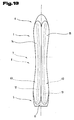
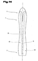
- Fig. 13 to 16 are plan views of various embodiments of the sliding device 1 according to the invention shown, wherein the dashed lines the shape or the course of integrated mold sections 12; 13; 56; 57 or corresponding double profiles 63 illustrate.
- Fig. 13 to 15 are each two juxtaposed shape profiles 12; 13; 56; 57 or double profiles 63 integrated in Gleitterrorism emotions. To Fig. 13 these also extend arcuately in plan view of the sliding device 1. A distance between the adjacent mold profiles 12; 13; 56; 57 in the binding mounting area 8 is smaller than the distance between the mold sections 12; 13; 56; 57 in the end regions 5. 6 of the sliding device 1. That is, in the binding mounting area 8, the longitudinally curved mold sections 12; 13; 56; 57 the smallest relative distance from each other.
- the mold profiles 12; 13; 56; 57 in plan view of the slider 1 but also be V-shaped aligned and thereby run largely straight or even be provided with a longitudinal curvature.
- the imaginary or actual intersection of the V-shaped shaped profiles 12; 13; 56; 57 is assigned either to the blade-side end region 6 or the opposite end region 5 of the sliding device 1.
- Fig. 15 the mold profiles 12; 13; 56; 57 but also be crossed over each other in the slider 1 integrated.
- a crossover point 71 of the mold profiles 12; 13; 56; 57 is preferably located approximately in the central region 7 or in the binding mounting region 8 of the sliding device 1.
- the molded sections 12; 13; 56; 57 adapted accordingly or permanently deformed.
- Fig. 16 are several mold profiles 12; 13; 56; 57 or more double profiles 63 placed side by side.
- three profile strands are provided, the middle profile strand is substantially rectilinear and the two adjacent outer profile strands approximately like the sidecut run or approximately equal to the nearest side edge 72, 73 of the sliding device 1 are formed.
Landscapes
- Laminated Bodies (AREA)
- Road Paving Structures (AREA)
- Footwear And Its Accessory, Manufacturing Method And Apparatuses (AREA)
- Toys (AREA)
- Materials Applied To Surfaces To Minimize Adherence Of Mist Or Water (AREA)
- Dry Formation Of Fiberboard And The Like (AREA)
- Lubricants (AREA)
- Measurement Of Force In General (AREA)
Claims (21)
- Appareil de glisse en forme de planche (1), en particulier ski (2) ou planche à neige, en plusieurs couches disposées entre un revêtement de face de glissement (25) et une couche de recouvrement (24), comprenant un brin supérieur (31) le plus proche de la couche de recouvrement (24) et/ou un brin inférieur (32) le plus proche d'un revêtement de face de glissement (25) en matériau hautement résistant, où ces couches forment avec un noyau disposé entre les couches au moins un élément composite, et avec au moins deux profilés de forme (12, 13 ; 56, 57) associés au noyau ou formant le noyau, en une vue de dessus sur l'appareil de glisse (1) disposés l'un à côté de l'autre, qui sont noyés ou logés au moins avec des zones partielles de leur face d'enveloppe dans une couche (44, 45) en matériau synthétique élastique, de préférence dans une couche (44, 45) en matériau synthétique mousse, résiliante et avec un rappel élastique sous l'effet d'une force par rapport aux profilés de forme (12, 13 ; 56, 57), où les formes en section transversale et/ou les dimensions en section transversale des profilés de forme intégrés (12, 13 ; 56, 57) sont adaptés au moins approximativement à un profilage de surface de l'appareil de glisse (1) respectivement sont codéterminantes pour le profilage de surface de l'appareil de glisse (1), caractérisé en ce que les profilés de forme intégrés (12, 13 ; 56, 57), en vue de dessus de l'appareil de glisse (1), sont courbés en forme d'arc, où un écart entre les profilés de forme avoisinants, courbés en longueur (12, 13 ; 56, 57) dans la zone de montage (8) de la fixation de l'appareil de glisse (1) est plus petit qu'un écart entre les profilés de forme (12, 13 ; 56, 57) dans les zones d'extrémité (5, 6) de l'appareil de glisse (1).
- Appareil de glisse en forme de planche selon la revendication 1, caractérisé en ce que les profilés de forme (12, 13 ; 56, 57) sont logés de tout côté d'une manière élastique dans une couche (44, 45) en matériau synthétique mousse élastomère avec un poids spécifique de 200 kg/m3 à 400kg/m3, de préférence 300 kg/m3 respectivement sont retenus dans celle-ci en étant entourés tout autour.
- Appareil de glisse en forme de planche selon la revendication 1 ou 2, caractérisé en ce que le matériau synthétique mousse est formé par une mousse de polyuréthane élastomère expansée.
- Appareil de glisse en forme de planche selon l'une ou plusieurs des revendications précédentes, caractérisé en ce qu'au moins une zone partielle des enveloppes extérieures des profilés de forme (12, 13 ; 56, 57), en intercalant la couche élastique (44, 45), s'étend près du brin inférieur et/ou supérieur (30 ; 31).
- Appareil de glisse en forme de planche selon l'une ou plusieurs des revendications précédentes, caractérisé en ce qu'au moins une zone partielle de la face d'enveloppe des profilés de forme (12, 13), en intercalant la couche élastique (44, 45), s'appuie à des faces intérieures (54, 55) de ces profilés de forme extérieurs (56, 57), entourant ces profilés de forme (12, 13) au moins partiellement.
- Appareil de glisse en forme de planche selon l'une ou plusieurs des revendications précédentes, caractérisé en ce que le composite formé par le matériau synthétique élastique et les profilés de forme (12, 13 ; 56, 57) constitue un composant de noyau (39) multi-couche, pouvant être préfabriqué.
- Appareil de glisse en forme de planche selon l'une des revendications précédentes, caractérisé en ce que les profilés de forme (12, 13 ; 56, 57) sont formés par des profilés creux (42, 43) avec une face d'enveloppe fermée.
- Appareil de glisse en forme de planche selon la revendication 5, caractérisé en ce qu'au moins les profilés de forme intérieurs (12, 13) sont formés par des profilés creux tubulaires (42, 43).
- Appareil de glisse en forme de planche selon la revendication 5, caractérisé en ce que le profilé de forme extérieur (56, 57) est réalisé en section transversale en forme de U-, V- ou de cuvette et enveloppe au moins une zone de face d'enveloppe supérieure du profilé de forme (12, 13) disposé en-dessous.
- Appareil de glisse en forme de planche selon la revendication 5, caractérisé en ce que les profilés de forme intérieurs (12, 13), en intercalant la couche élastique (44, 45), sont reçus dans des profilés de forme tubulaires extérieurs (56, 57).
- Appareil de glisse en forme de planche selon l'une ou plusieurs des revendications précédentes, caractérisé en ce que la couche élastique (44, 45) est formée par un matériau synthétique moussant, formant le noyau en mousse (41) de l'appareil de glisse (1).
- Appareil de glisse en forme de planche selon l'une ou plusieurs des revendications précédentes, caractérisé en ce que la couche élastique (44, 45) est formée par une enveloppe des profilés de forme (12, 13 ; 56, 57) en un matériau élastomère, par exemple en des matériaux de silicone et/ou de caoutchouc.
- Appareil de glisse en forme de planche selon l'une ou plusieurs des revendications précédentes, caractérisé en ce que les profilés de forme (12, 13) s'appliquent directement à un côté inférieur du brin supérieur (31) en matériau hautement solide et, dans la zone opposée, sont espacées par la couche élastique (44, 45) du brin inférieur hautement solide (30) respectivement des couches inférieures de l'appareil de glisse (1).
- Appareil de glisse en forme de planche selon l'une ou plusieurs des revendications précédentes, caractérisé en ce qu'une hauteur (48) des profilés de forme (12, 13 ; 56, 57), en partant d'une zone médiane (7) de l'appareil de glisse (1) formant la zone de montage (8) de la fixation, diminue vers ses extrémités.
- Appareil de glisse en forme de planche selon la revendication 5, caractérisé en ce que le profilé de forme extérieur (56, 57) est elliptique en section transversale.
- Appareil de glisse en forme de planche selon la revendication 5, caractérisé en ce que les profilés de forme intérieur ou extérieur (12, 13 ; 56, 57) s'étendent d'une manière continue jusque dans des plages de zone de contact espacées (18, 19) d'un appareil de glissement non chargé (1) avec un fond (22), et que l'autre des profilés de forme emboîtés (12, 13 ; 56, 57) est comparativement plus court.
- Appareil de glisse en forme de planche selon la revendication 5, caractérisé en ce que les profilés de forme intérieurs (12, 13) s'étendent au-delà des deux extrémités des profilés de forme extérieurs (56, 57) jusque dans la plage des zones de contact (18, 19) du côté inférieur d'un appareil de glisse non chargé (1) avec un fond plan (22) et en intercalant la couche élastique (44, 45), sont découplés complètement des profilés de forme extérieurs (56, 57).
- Appareil de glisse en forme de planche selon la revendication 5, caractérisé en ce que les profilés de forme tubulaires extérieurs (56, 57), à leurs extrémités sont aplatis et, à l'intérieur, les profilés de forme comparativement plus courts (12, 13) sont entourés tout autour par la couche élastique (44, 45), respectivement sont noyés dans celle-ci.
- Appareil de glisse en forme de planche selon la revendication 5, caractérisé en ce que la couche élastomère (44, 45) est réalisée pour la mise à distance des profilés de forme intérieurs et extérieurs (12, 13 ; 56, 57) et pour former au moins un espace creux (61, 62) entre les profilés de forme intérieurs et extérieurs (12, 13 ; 56, 57) est réalisée comme baguette d'écartement élastique.
- Appareil de glisse sous forme de planche selon la revendication 19, caractérisé en ce qu'au moins une baguette d'écartement est orientée de telle sorte que au-dessus et/ou en dessous des profilés de forme intérieurs (12, 13) est formé un espace creux (61, 62) délimité par les profilés de forme extérieurs (56, 57).
- Appareil de glisse en forme de planche selon la revendication 19, caractérisé en ce que les baguettes d'écartement élastiques entre les profilés de forme intérieurs et extérieurs (12, 13 ; 56, 57) sont orientés verticalement et sont dimensionnés de telle sorte que dans au moins l'une des deux zones latérales, entre les profilés de forme intérieurs et extérieurs (12, 13 ; 56, 57), un espace creux (61, 62) est réalisé.
Applications Claiming Priority (3)
| Application Number | Priority Date | Filing Date | Title |
|---|---|---|---|
| AT215799 | 1999-12-22 | ||
| AT0215799A AT411869B (de) | 1999-12-22 | 1999-12-22 | Brettartiges gleitgerät, insbesondere schi oder snowboard |
| PCT/AT2000/000342 WO2001045811A1 (fr) | 1999-12-22 | 2000-12-14 | Appareil de glisse en forme de planche, en particulier ski et planche a neige |
Publications (2)
| Publication Number | Publication Date |
|---|---|
| EP1239929A1 EP1239929A1 (fr) | 2002-09-18 |
| EP1239929B1 true EP1239929B1 (fr) | 2008-07-23 |
Family
ID=3528984
Family Applications (1)
| Application Number | Title | Priority Date | Filing Date |
|---|---|---|---|
| EP00986851A Expired - Lifetime EP1239929B1 (fr) | 1999-12-22 | 2000-12-14 | Appareil de glisse en forme de planche, en particulier ski et planche a neige |
Country Status (6)
| Country | Link |
|---|---|
| US (1) | US6886848B2 (fr) |
| EP (1) | EP1239929B1 (fr) |
| AT (2) | AT411869B (fr) |
| AU (1) | AU2328001A (fr) |
| DE (1) | DE50015277D1 (fr) |
| WO (1) | WO2001045811A1 (fr) |
Families Citing this family (21)
| Publication number | Priority date | Publication date | Assignee | Title |
|---|---|---|---|---|
| AUPR838601A0 (en) * | 2001-10-19 | 2001-11-15 | Alexander, Keith | Skateboard wear and impact damage reduction pins/strips |
| DE10204330A1 (de) * | 2002-02-01 | 2003-08-14 | Innotec Ges Zur Entwicklung In | Alpinski |
| FR2845296B1 (fr) * | 2002-10-03 | 2004-12-24 | Salomon Sa | Planche de glisse ou de roulage |
| AT500325A1 (de) * | 2002-11-06 | 2005-12-15 | Tyrolia Technology Gmbh | Gleitbrett, insbesondere ski |
| FR2851475B1 (fr) * | 2003-02-26 | 2006-10-13 | Salomon Sa | Paire de skis prevus pour la pratique de la glisse et notamment du ski alpin |
| FR2869811B1 (fr) * | 2004-05-05 | 2006-06-02 | Skis Rossignol Sa Sa | Planche de glisse |
| CN100425309C (zh) * | 2004-06-10 | 2008-10-15 | 伟立兴业股份有限公司 | 易握滑板本体结构 |
| EP1693089B1 (fr) * | 2005-02-16 | 2009-01-07 | Skis Rossignol | Planche de glisse |
| SI22083B (sl) * | 2005-07-18 | 2009-12-31 | Elan, D.O.O. | Smučka ali snežna deska z izboljšano torzijsko togostjo |
| DE102005054985A1 (de) * | 2005-11-16 | 2007-05-24 | Marker Völkl International GmbH | Schneegleitbrett sowie Schalenbauteil für ein Schneegleitbrett |
| AT504069B1 (de) * | 2006-07-26 | 2009-08-15 | Atomic Austria Gmbh | Schi oder snowboard mit mitteln zur beeinflussung von dessen querschnittsform |
| FR2909893B1 (fr) * | 2006-12-14 | 2010-01-15 | Alain Zanco | Mecanisation optimisee pour une planche de glisse sur neige. |
| FR2926735B1 (fr) * | 2008-01-25 | 2010-03-26 | Salomon Sa | Ski alpin avec moyens de reglage |
| FR2947182B1 (fr) * | 2009-06-26 | 2011-09-09 | Salomon Sas | Planche de glisse |
| US20110206895A1 (en) * | 2010-01-26 | 2011-08-25 | Drake Powderworks Llc | Carbon fiber laminate ski or snowboard with metal rib core dampening system |
| US8556289B2 (en) * | 2011-01-19 | 2013-10-15 | Flow Sports, Inc. | Sports board having deformable base feature |
| US9305120B2 (en) | 2011-04-29 | 2016-04-05 | Bryan Marc Failing | Sports board configuration |
| US8820770B2 (en) * | 2011-10-12 | 2014-09-02 | Paul Speirer | Ski, snowboard, or monoboard with depth indicator |
| RU2634583C1 (ru) * | 2016-08-31 | 2017-10-31 | Александр Поликарпович Лялин | Двухместный сноуборд |
| US10486051B2 (en) * | 2017-09-26 | 2019-11-26 | Boosted, Inc. | Backpack for a personal transport vehicle |
| US12239898B1 (en) | 2024-10-31 | 2025-03-04 | Dennis Malos | Carbon fiber snowboard |
Family Cites Families (25)
| Publication number | Priority date | Publication date | Assignee | Title |
|---|---|---|---|---|
| US2377504A (en) * | 1943-11-24 | 1945-06-05 | Cairns Corp | Metal ski |
| CA932350A (en) * | 1970-01-16 | 1973-08-21 | F. Wilkes Donald | Ski bindings |
| DE2227980A1 (de) * | 1972-06-08 | 1974-01-03 | Heinz Bildner | Radial-ski mit profilierter laufsohle |
| US3940157A (en) * | 1973-02-07 | 1976-02-24 | Nippon Gakki Seizo Kabushiki Kaisha | Ski structure |
| CH604768A5 (fr) * | 1975-06-20 | 1978-09-15 | Rossignol Sa | |
| US4545597A (en) * | 1981-11-04 | 1985-10-08 | Olin Corporation | Reinforcing ribs in a snow ski with a wood/foam core |
| ATE16460T1 (de) | 1981-12-15 | 1985-11-15 | Dynamic Sa | Leichtgebauter ski mit kern und sein herstellungsverfahren. |
| EP0081834B1 (fr) | 1981-12-15 | 1985-11-13 | DYNAMIC Société Anonyme dite: | Ski du type à noyau à structure allégée et son procédé de fabrication |
| DE3437865A1 (de) * | 1983-10-21 | 1985-05-09 | Kabushiki Kaisha Swallow Ski, Iiyama, Nagano | Herstellungsverfahren fuer skier |
| NO870539L (no) * | 1986-02-21 | 1987-08-24 | Rohrmoser Alois Skifabrik | Forsterkningselement for inkorporering i en harpiks og anvendelse av dette elementet. |
| FR2610525A1 (fr) * | 1987-02-05 | 1988-08-12 | Salomon Sa | Ski de fond presentant une nervure longitudinale en saillie par rapport a sa face superieure |
| FR2615406B1 (fr) * | 1987-05-22 | 1989-07-21 | Salomon Sa | Ski a amortissement reparti |
| FR2615404B1 (fr) * | 1987-05-22 | 1989-09-01 | Salomon Sa | Ski a amortissement reparti |
| FR2654645B1 (fr) * | 1989-11-22 | 1992-08-28 | Salomon Sa | Procede de realisation d'un ski par injection, et structure de ski obtenue par ce procede. |
| US5141243A (en) * | 1990-01-22 | 1992-08-25 | Pacific Coast Composites, Inc. | Alpine ski with a simplified construction |
| AT397209B (de) * | 1990-09-27 | 1994-02-25 | Rohrmoser Alois Skifabrik | Ski mit einer räumlich profilierten oberseite |
| FR2684012B1 (fr) * | 1991-11-22 | 1994-08-05 | Rossignol Sa | Ski en forme, de section non rectangulaire. |
| FR2690814B1 (fr) * | 1992-05-06 | 1995-05-05 | Salomon Sa | Chausson pour chaussure de ski. |
| FR2692158B1 (fr) * | 1992-06-11 | 1994-12-16 | Rossignol Sa | Ski à profil perfectionné. |
| FR2700479B1 (fr) * | 1993-01-19 | 1995-02-24 | Rossignol Sa | Procédé de fabrication d'un ski à noyau injecté et à renfort interne ajouré, et ski obtenu par ce procédé. |
| FR2704440B1 (fr) * | 1993-04-30 | 1995-07-28 | Salomon Sa | Planche de glisse, notamment surf de neige. |
| DE4325091A1 (de) | 1993-07-27 | 1995-02-02 | Uwe Emig | Aus mehreren Elementen zusammengesetzter Ski |
| FR2714615B1 (fr) * | 1994-01-04 | 1996-02-16 | Rossignol Sa | Ski, ou autre planche de glisse sur neige, à noyau injecté "in situ". |
| DE19630465A1 (de) * | 1996-07-27 | 1998-01-29 | Franz Voelkl Gmbh & Co Ski Ten | Gleitbrett, insbesondere Snowboard oder Ski, Abstandhaltermatte für die Herstellung eines solchen Gleitbrettes sowie Verfahren zu seiner Herstellung |
| USD418545S (en) * | 1997-05-01 | 2000-01-04 | Donald Cassel | High strength snowboard |
-
1999
- 1999-12-22 AT AT0215799A patent/AT411869B/de not_active IP Right Cessation
-
2000
- 2000-12-14 WO PCT/AT2000/000342 patent/WO2001045811A1/fr not_active Ceased
- 2000-12-14 EP EP00986851A patent/EP1239929B1/fr not_active Expired - Lifetime
- 2000-12-14 US US10/168,512 patent/US6886848B2/en not_active Expired - Fee Related
- 2000-12-14 DE DE50015277T patent/DE50015277D1/de not_active Expired - Lifetime
- 2000-12-14 AT AT00986851T patent/ATE401940T1/de not_active IP Right Cessation
- 2000-12-14 AU AU23280/01A patent/AU2328001A/en not_active Abandoned
Also Published As
| Publication number | Publication date |
|---|---|
| EP1239929A1 (fr) | 2002-09-18 |
| AT411869B (de) | 2004-07-26 |
| US20030111824A1 (en) | 2003-06-19 |
| WO2001045811A1 (fr) | 2001-06-28 |
| WO2001045811A8 (fr) | 2001-09-20 |
| ATA215799A (de) | 2003-12-15 |
| DE50015277D1 (de) | 2008-09-04 |
| ATE401940T1 (de) | 2008-08-15 |
| US6886848B2 (en) | 2005-05-03 |
| AU2328001A (en) | 2001-07-03 |
Similar Documents
| Publication | Publication Date | Title |
|---|---|---|
| AT411869B (de) | Brettartiges gleitgerät, insbesondere schi oder snowboard | |
| DE4322300C2 (de) | Ski mit einer Schale, einem Untergurt sowie einem vorzugsweise in die Schale integrierten Obergurt und Verfahren zum Herstellen eines Skis | |
| AT401350B (de) | Alpinski | |
| DE69302208T2 (de) | Ski mit einer Lauffläche und einer zweiteiligen Versteifung, die an der Lauffläche angebracht ist | |
| DE69221224T2 (de) | Fortbildung für Dämpfungseinrichtung für Skis | |
| AT397209B (de) | Ski mit einer räumlich profilierten oberseite | |
| DE102005006267B3 (de) | Schuhsohle und Schuh | |
| DE4124965B4 (de) | Plattenförmige Dämpfungsvorrichtung für eine Schibindung | |
| AT400524B (de) | Schi | |
| EP1239928B1 (fr) | Dispositif de glisse de type planche, en particulier ski ou surf des neiges | |
| AT6612U1 (de) | Ski zum ausüben des alpinen skifahrens sowie ski mit bindungsplatte | |
| AT401349B (de) | Alpinski | |
| DE69101280T2 (de) | Ski mit gerippter Oberfläche. | |
| DE3240717A1 (de) | Ski | |
| DE69108001T2 (de) | Ski für Wintersport mit Montagebühne für Skibindungen. | |
| EP1286732B1 (fr) | Element de renforcement et/ou d'amortissement pour dispositif de glissement, notamment pour ski ou planche a neige | |
| AT402693B (de) | Alpinski | |
| EP2272573A1 (fr) | Planche de glisse sous la forme d'un ski ou d'un snowboard | |
| DE69201341T2 (de) | Ski mit einem nicht-rechteckigen Durchschnitt. | |
| EP0711190B1 (fr) | Ski compose de plusieurs elements | |
| AT405139B (de) | Gleitgerät | |
| DE4017539A1 (de) | Ski mit einem zumindest im obergurt integrierten sandwichgurt | |
| AT406124B (de) | Skiaufbau | |
| EP1952856A1 (fr) | Ski ou snow-board doté d'un élément de transmission de force de type plaque | |
| EP1562682B1 (fr) | Ski de descente |
Legal Events
| Date | Code | Title | Description |
|---|---|---|---|
| PUAI | Public reference made under article 153(3) epc to a published international application that has entered the european phase |
Free format text: ORIGINAL CODE: 0009012 |
|
| 17P | Request for examination filed |
Effective date: 20020619 |
|
| AK | Designated contracting states |
Kind code of ref document: A1 Designated state(s): AT BE CH CY DE DK ES FI FR GB GR IE IT LI LU MC NL PT SE TR |
|
| AX | Request for extension of the european patent |
Free format text: AL;LT;LV;MK;RO;SI PAYMENT 20020712 |
|
| 17Q | First examination report despatched |
Effective date: 20061117 |
|
| GRAP | Despatch of communication of intention to grant a patent |
Free format text: ORIGINAL CODE: EPIDOSNIGR1 |
|
| GRAS | Grant fee paid |
Free format text: ORIGINAL CODE: EPIDOSNIGR3 |
|
| GRAA | (expected) grant |
Free format text: ORIGINAL CODE: 0009210 |
|
| AK | Designated contracting states |
Kind code of ref document: B1 Designated state(s): AT BE CH CY DE DK ES FI FR GB GR IE IT LI LU MC NL PT SE TR |
|
| AX | Request for extension of the european patent |
Extension state: SI |
|
| REG | Reference to a national code |
Ref country code: GB Ref legal event code: FG4D Free format text: NOT ENGLISH |
|
| REG | Reference to a national code |
Ref country code: CH Ref legal event code: EP |
|
| REG | Reference to a national code |
Ref country code: IE Ref legal event code: FG4D Free format text: LANGUAGE OF EP DOCUMENT: GERMAN |
|
| REF | Corresponds to: |
Ref document number: 50015277 Country of ref document: DE Date of ref document: 20080904 Kind code of ref document: P |
|
| REG | Reference to a national code |
Ref country code: CH Ref legal event code: NV Representative=s name: ABP PATENT NETWORK SWISS GMBH |
|
| NLV1 | Nl: lapsed or annulled due to failure to fulfill the requirements of art. 29p and 29m of the patents act | ||
| PG25 | Lapsed in a contracting state [announced via postgrant information from national office to epo] |
Ref country code: ES Free format text: LAPSE BECAUSE OF FAILURE TO SUBMIT A TRANSLATION OF THE DESCRIPTION OR TO PAY THE FEE WITHIN THE PRESCRIBED TIME-LIMIT Effective date: 20081103 Ref country code: PT Free format text: LAPSE BECAUSE OF FAILURE TO SUBMIT A TRANSLATION OF THE DESCRIPTION OR TO PAY THE FEE WITHIN THE PRESCRIBED TIME-LIMIT Effective date: 20081223 Ref country code: NL Free format text: LAPSE BECAUSE OF FAILURE TO SUBMIT A TRANSLATION OF THE DESCRIPTION OR TO PAY THE FEE WITHIN THE PRESCRIBED TIME-LIMIT Effective date: 20080723 |
|
| PG25 | Lapsed in a contracting state [announced via postgrant information from national office to epo] |
Ref country code: FI Free format text: LAPSE BECAUSE OF FAILURE TO SUBMIT A TRANSLATION OF THE DESCRIPTION OR TO PAY THE FEE WITHIN THE PRESCRIBED TIME-LIMIT Effective date: 20080723 |
|
| REG | Reference to a national code |
Ref country code: IE Ref legal event code: FD4D |
|
| PG25 | Lapsed in a contracting state [announced via postgrant information from national office to epo] |
Ref country code: DK Free format text: LAPSE BECAUSE OF FAILURE TO SUBMIT A TRANSLATION OF THE DESCRIPTION OR TO PAY THE FEE WITHIN THE PRESCRIBED TIME-LIMIT Effective date: 20080723 Ref country code: IE Free format text: LAPSE BECAUSE OF FAILURE TO SUBMIT A TRANSLATION OF THE DESCRIPTION OR TO PAY THE FEE WITHIN THE PRESCRIBED TIME-LIMIT Effective date: 20080723 |
|
| PLBE | No opposition filed within time limit |
Free format text: ORIGINAL CODE: 0009261 |
|
| STAA | Information on the status of an ep patent application or granted ep patent |
Free format text: STATUS: NO OPPOSITION FILED WITHIN TIME LIMIT |
|
| BERE | Be: lapsed |
Owner name: ATOMIC AUSTRIA GMBH Effective date: 20081231 |
|
| 26N | No opposition filed |
Effective date: 20090424 |
|
| PG25 | Lapsed in a contracting state [announced via postgrant information from national office to epo] |
Ref country code: MC Free format text: LAPSE BECAUSE OF NON-PAYMENT OF DUE FEES Effective date: 20081231 |
|
| GBPC | Gb: european patent ceased through non-payment of renewal fee |
Effective date: 20081214 |
|
| PG25 | Lapsed in a contracting state [announced via postgrant information from national office to epo] |
Ref country code: IT Free format text: LAPSE BECAUSE OF FAILURE TO SUBMIT A TRANSLATION OF THE DESCRIPTION OR TO PAY THE FEE WITHIN THE PRESCRIBED TIME-LIMIT Effective date: 20080723 |
|
| PG25 | Lapsed in a contracting state [announced via postgrant information from national office to epo] |
Ref country code: BE Free format text: LAPSE BECAUSE OF NON-PAYMENT OF DUE FEES Effective date: 20081231 |
|
| REG | Reference to a national code |
Ref country code: FR Ref legal event code: ST Effective date: 20090831 |
|
| PG25 | Lapsed in a contracting state [announced via postgrant information from national office to epo] |
Ref country code: GB Free format text: LAPSE BECAUSE OF NON-PAYMENT OF DUE FEES Effective date: 20081214 |
|
| PG25 | Lapsed in a contracting state [announced via postgrant information from national office to epo] |
Ref country code: SE Free format text: LAPSE BECAUSE OF FAILURE TO SUBMIT A TRANSLATION OF THE DESCRIPTION OR TO PAY THE FEE WITHIN THE PRESCRIBED TIME-LIMIT Effective date: 20081023 |
|
| PGFP | Annual fee paid to national office [announced via postgrant information from national office to epo] |
Ref country code: CH Payment date: 20091215 Year of fee payment: 10 |
|
| PG25 | Lapsed in a contracting state [announced via postgrant information from national office to epo] |
Ref country code: FR Free format text: LAPSE BECAUSE OF NON-PAYMENT OF DUE FEES Effective date: 20081231 |
|
| PG25 | Lapsed in a contracting state [announced via postgrant information from national office to epo] |
Ref country code: AT Free format text: LAPSE BECAUSE OF NON-PAYMENT OF DUE FEES Effective date: 20081214 |
|
| PGFP | Annual fee paid to national office [announced via postgrant information from national office to epo] |
Ref country code: DE Payment date: 20091222 Year of fee payment: 10 |
|
| PG25 | Lapsed in a contracting state [announced via postgrant information from national office to epo] |
Ref country code: LU Free format text: LAPSE BECAUSE OF NON-PAYMENT OF DUE FEES Effective date: 20081214 Ref country code: CY Free format text: LAPSE BECAUSE OF FAILURE TO SUBMIT A TRANSLATION OF THE DESCRIPTION OR TO PAY THE FEE WITHIN THE PRESCRIBED TIME-LIMIT Effective date: 20080723 |
|
| PG25 | Lapsed in a contracting state [announced via postgrant information from national office to epo] |
Ref country code: TR Free format text: LAPSE BECAUSE OF FAILURE TO SUBMIT A TRANSLATION OF THE DESCRIPTION OR TO PAY THE FEE WITHIN THE PRESCRIBED TIME-LIMIT Effective date: 20080723 |
|
| PG25 | Lapsed in a contracting state [announced via postgrant information from national office to epo] |
Ref country code: GR Free format text: LAPSE BECAUSE OF FAILURE TO SUBMIT A TRANSLATION OF THE DESCRIPTION OR TO PAY THE FEE WITHIN THE PRESCRIBED TIME-LIMIT Effective date: 20081024 |
|
| REG | Reference to a national code |
Ref country code: CH Ref legal event code: PL |
|
| PG25 | Lapsed in a contracting state [announced via postgrant information from national office to epo] |
Ref country code: LI Free format text: LAPSE BECAUSE OF NON-PAYMENT OF DUE FEES Effective date: 20101231 Ref country code: CH Free format text: LAPSE BECAUSE OF NON-PAYMENT OF DUE FEES Effective date: 20101231 |
|
| PG25 | Lapsed in a contracting state [announced via postgrant information from national office to epo] |
Ref country code: DE Free format text: LAPSE BECAUSE OF NON-PAYMENT OF DUE FEES Effective date: 20110701 |
|
| REG | Reference to a national code |
Ref country code: DE Ref legal event code: R119 Ref document number: 50015277 Country of ref document: DE Effective date: 20110701 |