EP1241089A2 - Dispositif d'entraínement pour bicyclette à moteur - Google Patents
Dispositif d'entraínement pour bicyclette à moteur Download PDFInfo
- Publication number
- EP1241089A2 EP1241089A2 EP01128246A EP01128246A EP1241089A2 EP 1241089 A2 EP1241089 A2 EP 1241089A2 EP 01128246 A EP01128246 A EP 01128246A EP 01128246 A EP01128246 A EP 01128246A EP 1241089 A2 EP1241089 A2 EP 1241089A2
- Authority
- EP
- European Patent Office
- Prior art keywords
- drive
- chain
- sprocket
- cycle
- motor
- Prior art date
- Legal status (The legal status is an assumption and is not a legal conclusion. Google has not performed a legal analysis and makes no representation as to the accuracy of the status listed.)
- Withdrawn
Links
Images



Classifications
-
- B—PERFORMING OPERATIONS; TRANSPORTING
- B62—LAND VEHICLES FOR TRAVELLING OTHERWISE THAN ON RAILS
- B62M—RIDER PROPULSION OF WHEELED VEHICLES OR SLEDGES; POWERED PROPULSION OF SLEDGES OR SINGLE-TRACK CYCLES; TRANSMISSIONS SPECIALLY ADAPTED FOR SUCH VEHICLES
- B62M6/00—Rider propulsion of wheeled vehicles with additional source of power, e.g. combustion engine or electric motor
- B62M6/40—Rider propelled cycles with auxiliary electric motor
- B62M6/70—Rider propelled cycles with auxiliary electric motor power-driven at single endless flexible member, e.g. chain, between cycle crankshaft and wheel axle, the motor engaging the endless flexible member
Definitions
- the present invention relates to an auxiliary power drive for chain driven systems, and more particularly, to a roller sprocket auxiliary drive for a pedal cycle.
- this power assist should function in conjunction with the pedal power of the cycle and should utilize the existing gearing systems of the chain drive.
- the power assist device should be simple to attach to and remove from a wide number of pedal cycle configurations. Moreover, the power assist device should be lightweight, rugged and simple to operate.
- U.S. Patent No. 5,242,028 discloses a motorized bicycle drive system which drives the bicycle independent of the pedal drive, employing a separate drive chain. Such a device is complex and difficult to install.
- An object of the present invention is to provide a power drive attachment which bears directly on the existing chain drive of a pedal cycle and is simple to install.
- Another object of the present invention is to provide a drive sprocket incorporating a free wheel hub which permits pedal power without drive motor rotation, even though the power drive unit remains engaged with the chain or chain ring.
- a further object of the present invention is that the existing pedal cycle rear sprocket gear ratios can also be utilized by the power drive attachment.
- Still another object of the present invention is the mounting system which is combined with a roller drive sprocket hub, which enables quick attachment and also accommodates irregularities in the alignment between the sprocket and the cycle chain ring.
- the present invention introduces a compact drive motor mounted adjacent the chain ring of a pedal cycle, such that the power assist drive can apply tension to the associated drive chain, and can supplement or replace pedal power through the combination of drive components.
- a power drive attachment for a pedal cycle includes a frame, a pair of pedals, a drive chain and a chain ring mounted on the frame.
- the power drive attachment includes a drive motor mounted on the frame of the cycle.
- An output drive sprocket is mounted on the motor in close vicinity to the chain ring, wherein the drive chain is captured between the drive sprocket and the chain ring.
- Means pivotally mount the drive motor and sprocket on the cycle frame for increasing the tension on the drive chain and for accommodating irregularities in the alignment between the drive sprocket and the drive chain.
- a power drive attachment in a second embodiment, includes a drive motor mounted on the frame of the cycle.
- An output drive sprocket is mounted on the motor for engaging an unoccupied portion of the chain ring.
- the drive sprocket includes roller tooth means for engaging a section of the chain ring or rear sprocket which is not communicating with the drive chain, to drive the cycle.
- Figure 1 is a side view of a pedal cycle incorporating a first embodiment of a power assist drive device of the present invention.
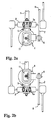
- Figure 2a is an enlarged cross-sectional view of the power assist drive device of the present invention taken along line I-I of Fig. 1 and mounted below the rear forks.
- Figure 2b illustrates mounting the power assist drive above the rear forks.
- FIGS. 3a and 3b are enlarged detail views of the pivot mounting arrangement of the power assist device of the present invention.
- Figure 4 is a cross-sectional view of the chain ring of the present invention including a free-wheel hub.
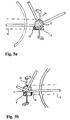
- Figure 5a is a perspective view of a roller drive sprocket of a second embodiment of the present invention, wherein the motor includes a right-angled drive.
- Figure 5b is a perspective view of the roller drive sprocket having an inline drive gear.
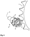
- Figure 6 is an enlarged perspective view of the roller sprocket of Figure 5.
- a power assist device 4 is mounted from a pivot plate 5 below a bottom bracket 3 of a standard bicycle frame 1.
- Power assist drive 4 includes a drive sprocket 6 which bears against the drive chain 8 of a standard bicycle as it leaves a chain ring 2.
- the cycle also includes multiple driven gears 7 on the rear cycle wheel.
- Power assist device 4 includes a motive source, such as an electric drive motor together with the appropriate attached gearing and an external electric energy supply 9, such as a storage battery, as is known in the prior art.
- the motor and associated drive gear which can be either an inline gear or right angled gear (see Figs. 5a and 5b, herein) which powers drive sprocket 6 is sufficiently compact to fit between pedal cranks 2a of a standard bicycle while maintaining adequate ground clearance.
- drive sprocket 6 is located immediately adjacent chain ring 2, which provides the regular power source from pedal rotation.
- drive chain 8 passes between drive sprocket 6 and chain ring 2. It is preferable that drive sprocket 6 bears on the non-tension or lower portion of drive chain 8, such that when providing power assist the sprocket actually further tensions the drive chain 8 as it pulls around chain ring 2.
- Drive sprocket 6 through its close proximity to chain ring 2 actually captures the drive chain therebetween.
- the compact gear drive motor includes a right angle bevel drive 11, shown in Fig. 2, as well as a one way clutch. Pivoting attachment 5 is mounted to the bracket 3, which will be described further herein.
- the drive sprocket can be arranged to free-wheel and thus the power assist device 4 can idle when not in use, even though still engaged to the drive chain 8.
- the cycle can be powered by the cycle pedals, with the pawls of the wheels locked and the motor idle, or motor driven, with the pawls of the rear driven wheel and the pawl of the power assist assembly 4 being locked, and the pedals idle.
- Figs. 3A and 3B provide a further illustration of pivot mounting 5.
- the drive sprocket 6 is thrust upward and onto the drive chain 8 with a pressure typically several times the mass of the pivoting motor 4, because the sprocket is proportionally closer to pivot 5 then the center of mass of the device 4, see Fig. 3A.
- the powered sprocket pulls the chain and swings motor 4.
- Fig. 3B when the drive sprocket is idle and not clamping the chain, the sprocket and motor assembly 4 are pivoted downward.
- Fig. 4 illustrates chain ring 2 having a one way clutch.
- Chain ring 2 includes pawls 16 for a free-wheel hub having bearings 17 which can be incorporated permitting power assist to be applied to drive chain 8, thus rotating the chain ring while the pedal cranks remain stationary.
- Figs. 5A, 5B and 6 illustrate a second embodiment of the drive sprocket, in the form of a roller tooth sprocket 10.
- the drive chain 8 does not pass between sprocket 10 and chain ring 2.
- Roller sprocket 10 includes a plurality of chain links 12 coupled into a ring and press fit onto a hub 14 of the sprocket.
- the roller tooth sprocket is free to rotate as with a standard chain.
- the roller sprocket can directly engage the teeth of chain ring 2.
- Roller sprocket 10 directly engages an unoccupied rear sector of chain ring 2, utilizing its own rollers (chain links 12) in place of existing drive chain 8.
- the motor and gear box are such that the drive in inlined at an angle in Fig. 5A and inline in Fig. 5B.
- drive sprocket 10 can be a free-wheel hub incorporating caged bearings, needle clutch or pawls 16.
- the drive sprocket becomes free to move laterally on its axis within the limits of the chain, becoming a chain and associated chain ring follower in the course of rotation either when delivering power or when idling.
- the drive shaft 15 is somewhat longer than the needle bearing clutch forming the free wheel hub, then the assembly is free to move axially along the shaft.
- the various needles of the clutch of sprocket 10 turn slightly, this movement bears against the drive shaft 15 moving the sprocket along shaft 15.
- Substantial axial misalignment for example, at least 1/4 inch
- radial misalignment for example, at least 1/8 inch, can be accommodated from the action of the teeth engaging the chain.
- Power assist device 4 becomes a more practical add-on device to existing cycles in that it can adjust alignment to accommodate deficiencies either in installation or in the perfection of the machine or frame 1 to which it is attached.
- the drive assembly 4 is clamped under the rear forks, 1a, see Fig. 2A. or above, see Fig. 2B.
- the device 4 can be slid forward into this region and roughly aligned until the drive sprocket engages the chain ring. Brief rotation of the chain ring will force adequate clearances, while the chain links prevent the sprocket from moving to far axially and becoming misaligned.
- the mounting plate 5 can then be clamped tight.
- the present invention provides a quick attachment power device for pedal cycles and has a low center of gravity, the ability to utilize all gear ratios of the rear sprocket, a simple and rugged mounting, and the flexibility of power drive assist combined with pedal power, pedal power with no drive assist, or complete drive power.
Landscapes
- Engineering & Computer Science (AREA)
- Chemical & Material Sciences (AREA)
- Combustion & Propulsion (AREA)
- Transportation (AREA)
- Mechanical Engineering (AREA)
- Devices For Conveying Motion By Means Of Endless Flexible Members (AREA)
- Gears, Cams (AREA)
Applications Claiming Priority (2)
| Application Number | Priority Date | Filing Date | Title |
|---|---|---|---|
| US09/802,954 US6336516B1 (en) | 2001-03-12 | 2001-03-12 | Power drive attachment for pedal cycles |
| US802954 | 2001-03-12 |
Publications (1)
| Publication Number | Publication Date |
|---|---|
| EP1241089A2 true EP1241089A2 (fr) | 2002-09-18 |
Family
ID=25185175
Family Applications (1)
| Application Number | Title | Priority Date | Filing Date |
|---|---|---|---|
| EP01128246A Withdrawn EP1241089A2 (fr) | 2001-03-12 | 2001-11-28 | Dispositif d'entraínement pour bicyclette à moteur |
Country Status (2)
| Country | Link |
|---|---|
| US (1) | US6336516B1 (fr) |
| EP (1) | EP1241089A2 (fr) |
Cited By (1)
| Publication number | Priority date | Publication date | Assignee | Title |
|---|---|---|---|---|
| GB2380460B (en) * | 2001-10-04 | 2004-07-28 | Moulton Development Ltd | Power-assisted cycles |
Families Citing this family (10)
| Publication number | Priority date | Publication date | Assignee | Title |
|---|---|---|---|---|
| DE112005001121B4 (de) * | 2004-05-17 | 2014-02-13 | Magna Marque International Inc. | Fahrrad mit einem entfernbaren Kraftunterstützungsmodul |
| US7273123B2 (en) * | 2004-11-02 | 2007-09-25 | Te-Yu Perng | Electric bicycle power structure |
| US8602148B2 (en) * | 2008-01-29 | 2013-12-10 | Shaul Shwartz | Portable removable apparatus for powering a bicycle |
| US7604079B2 (en) * | 2008-02-12 | 2009-10-20 | Jack Ray Pittman | Power drive for a bicycle |
| CA2655366A1 (fr) * | 2008-02-29 | 2009-08-29 | Raymond Yee | Cyclomoteur |
| USD614084S1 (en) * | 2009-08-31 | 2010-04-20 | Sanyo Electric Co., Ltd. | Electric bicycle |
| US8573346B2 (en) * | 2010-01-08 | 2013-11-05 | Michael Dale Duignan | Auxiliary power driven unit for a bicycle |
| US9434445B1 (en) * | 2012-03-03 | 2016-09-06 | Dr. Nathan Jauvtis Engineering | Electronic bicycle |
| US9802674B2 (en) * | 2014-10-06 | 2017-10-31 | Ford Global Technologies, Llc | Power unit attachable to a bicycle |
| FR3054521B1 (fr) * | 2016-07-30 | 2020-03-13 | Ntn-Snr Roulements | Cycle equipe d'un module d'assistance electrique, et module d'assistance electrique pour un tel cycle |
Citations (1)
| Publication number | Priority date | Publication date | Assignee | Title |
|---|---|---|---|---|
| US5242028A (en) | 1992-01-24 | 1993-09-07 | Murphy Lisa J | Motorized bicycle drive system |
Family Cites Families (14)
| Publication number | Priority date | Publication date | Assignee | Title |
|---|---|---|---|---|
| US2457430A (en) | 1946-02-20 | 1948-12-28 | Argyris Stefanos | Electric bicycle |
| US2484472A (en) | 1948-08-10 | 1949-10-11 | Charles W Simpson | Propulsion aid for velocipedes |
| US3921745A (en) * | 1973-07-23 | 1975-11-25 | Mcculloch Corp | Electric bicycle |
| US3991843A (en) | 1974-06-28 | 1976-11-16 | The Lucas Electrical Company Limited | Cycles |
| GB1530131A (en) | 1975-01-21 | 1978-10-25 | Lucas Industries Ltd | Cycles |
| GB1546069A (en) | 1975-06-21 | 1979-05-16 | Lucas Industries Ltd | Cycle |
| GB1558564A (en) | 1975-07-03 | 1980-01-03 | Lucas Industries Ltd | Electrically assisted pedal-propelled vehicles |
| GB1585055A (en) | 1976-06-11 | 1981-02-25 | Lucas Industries Ltd | Cycles |
| GB8806042D0 (en) | 1988-03-14 | 1988-04-13 | Lean G D | Proportional control system for engine assisted bicycle |
| US4871042A (en) | 1988-09-01 | 1989-10-03 | Hsu Chi Chu | Electric bicycle |
| GB2249529A (en) | 1990-10-30 | 1992-05-13 | Hsu Chi Hsueh | Electric motor-assisted pedal bicycle with battery and solar power source |
| US5237263A (en) | 1991-06-17 | 1993-08-17 | Gannon Henry M | Electric and pedal driven bicycle with solar charging |
| JPH0550977A (ja) | 1991-08-19 | 1993-03-02 | Yasushi Sakano | 自転車 |
| JPH11124071A (ja) * | 1997-10-22 | 1999-05-11 | Suzuki Motor Corp | 電動補助自転車 |
-
2001
- 2001-03-12 US US09/802,954 patent/US6336516B1/en not_active Expired - Fee Related
- 2001-11-28 EP EP01128246A patent/EP1241089A2/fr not_active Withdrawn
Patent Citations (1)
| Publication number | Priority date | Publication date | Assignee | Title |
|---|---|---|---|---|
| US5242028A (en) | 1992-01-24 | 1993-09-07 | Murphy Lisa J | Motorized bicycle drive system |
Cited By (1)
| Publication number | Priority date | Publication date | Assignee | Title |
|---|---|---|---|---|
| GB2380460B (en) * | 2001-10-04 | 2004-07-28 | Moulton Development Ltd | Power-assisted cycles |
Also Published As
| Publication number | Publication date |
|---|---|
| US6336516B1 (en) | 2002-01-08 |
Similar Documents
| Publication | Publication Date | Title |
|---|---|---|
| US6336516B1 (en) | Power drive attachment for pedal cycles | |
| US20040050603A1 (en) | Mounting arrangement for vehicle power source | |
| CN114423675B (zh) | 电动辅助车辆推进系统 | |
| US6062329A (en) | Pedal bicycle having an auxiliary power means | |
| US7568714B2 (en) | Bicycle having a removable power assist module | |
| US20100001488A1 (en) | Construction kit and method for converting a bicycle. and bicycle | |
| US20050189157A1 (en) | Electric bicycles and retrofit kits | |
| EP0743238B1 (fr) | Détecteur de force de pédalage pour bicyclette assistée à moteur | |
| CA2312882A1 (fr) | Pedalier sans point mort, et ensemble comprenant un tel pedalier et un appareil de mesure | |
| US4393954A (en) | Motorized bicycle | |
| US20030141126A1 (en) | Electric bicycles and retrofit kits | |
| CN105480370B (zh) | 可附接到自行车的动力装置 | |
| CN113557195B (zh) | 电动自行车马达系统 | |
| EP0139714B1 (fr) | Systeme de transmission d'energie pour un velo | |
| WO2024060578A1 (fr) | Moteur de moyeu de roue et bicyclette à assistance électrique | |
| JP3156516B2 (ja) | 自動二輪車用エンジンの始動装置 | |
| US20030159869A1 (en) | Motorization of a bicycle with a simple replacement of the bottom bracket | |
| CN113968303A (zh) | 一种易装配的摇摆式三轮车 | |
| CN216102636U (zh) | 一种易装配的摇摆式三轮车 | |
| CN1120111C (zh) | 电动助力车辆的踏力检测装置 | |
| CN106828762B (zh) | 轮毂电机结合轴传动的自行车驱动系统 | |
| NL2028537B1 (en) | Mid-drive module for a pedal-powered vehicle | |
| CN219172600U (zh) | 一种采用后置轮毂电机的电助力自行车传动系统 | |
| RU159400U1 (ru) | Устройство для моторизации велосипеда | |
| RU179351U1 (ru) | Устройство для моторизации велосипеда |
Legal Events
| Date | Code | Title | Description |
|---|---|---|---|
| PUAI | Public reference made under article 153(3) epc to a published international application that has entered the european phase |
Free format text: ORIGINAL CODE: 0009012 |
|
| 17P | Request for examination filed |
Effective date: 20011128 |
|
| AK | Designated contracting states |
Kind code of ref document: A2 Designated state(s): AT BE CH CY DE DK ES FI FR GB GR IE IT LI LU MC NL PT SE TR |
|
| AX | Request for extension of the european patent |
Free format text: AL;LT;LV;MK;RO;SI |
|
| STAA | Information on the status of an ep patent application or granted ep patent |
Free format text: STATUS: THE APPLICATION IS DEEMED TO BE WITHDRAWN |
|
| 18D | Application deemed to be withdrawn |
Effective date: 20040602 |