EP1241122A2 - Musterübertragungsgerät und Musterübertragungsband - Google Patents
Musterübertragungsgerät und Musterübertragungsband Download PDFInfo
- Publication number
- EP1241122A2 EP1241122A2 EP02250799A EP02250799A EP1241122A2 EP 1241122 A2 EP1241122 A2 EP 1241122A2 EP 02250799 A EP02250799 A EP 02250799A EP 02250799 A EP02250799 A EP 02250799A EP 1241122 A2 EP1241122 A2 EP 1241122A2
- Authority
- EP
- European Patent Office
- Prior art keywords
- transfer
- mark
- tape
- bodily
- bodily sensing
- Prior art date
- Legal status (The legal status is an assumption and is not a legal conclusion. Google has not performed a legal analysis and makes no representation as to the accuracy of the status listed.)
- Withdrawn
Links
Images









Classifications
-
- B—PERFORMING OPERATIONS; TRANSPORTING
- B65—CONVEYING; PACKING; STORING; HANDLING THIN OR FILAMENTARY MATERIAL
- B65H—HANDLING THIN OR FILAMENTARY MATERIAL, e.g. SHEETS, WEBS, CABLES
- B65H37/00—Article or web delivery apparatus incorporating devices for performing specified auxiliary operations
- B65H37/002—Web delivery apparatus, the web serving as support for articles, material or another web
- B65H37/005—Hand-held apparatus
- B65H37/007—Applicators for applying coatings, e.g. correction, colour or adhesive coatings
-
- B—PERFORMING OPERATIONS; TRANSPORTING
- B41—PRINTING; LINING MACHINES; TYPEWRITERS; STAMPS
- B41F—PRINTING MACHINES OR PRESSES
- B41F17/00—Printing apparatus or machines of special types or for particular purposes, not otherwise provided for
-
- Y—GENERAL TAGGING OF NEW TECHNOLOGICAL DEVELOPMENTS; GENERAL TAGGING OF CROSS-SECTIONAL TECHNOLOGIES SPANNING OVER SEVERAL SECTIONS OF THE IPC; TECHNICAL SUBJECTS COVERED BY FORMER USPC CROSS-REFERENCE ART COLLECTIONS [XRACs] AND DIGESTS
- Y10—TECHNICAL SUBJECTS COVERED BY FORMER USPC
- Y10T—TECHNICAL SUBJECTS COVERED BY FORMER US CLASSIFICATION
- Y10T156/00—Adhesive bonding and miscellaneous chemical manufacture
- Y10T156/17—Surface bonding means and/or assemblymeans with work feeding or handling means
- Y10T156/1788—Work traversing type and/or means applying work to wall or static structure
- Y10T156/1795—Implement carried web supply
-
- Y—GENERAL TAGGING OF NEW TECHNOLOGICAL DEVELOPMENTS; GENERAL TAGGING OF CROSS-SECTIONAL TECHNOLOGIES SPANNING OVER SEVERAL SECTIONS OF THE IPC; TECHNICAL SUBJECTS COVERED BY FORMER USPC CROSS-REFERENCE ART COLLECTIONS [XRACs] AND DIGESTS
- Y10—TECHNICAL SUBJECTS COVERED BY FORMER USPC
- Y10T—TECHNICAL SUBJECTS COVERED BY FORMER US CLASSIFICATION
- Y10T156/00—Adhesive bonding and miscellaneous chemical manufacture
- Y10T156/18—Surface bonding means and/or assembly means with handle or handgrip
-
- Y—GENERAL TAGGING OF NEW TECHNOLOGICAL DEVELOPMENTS; GENERAL TAGGING OF CROSS-SECTIONAL TECHNOLOGIES SPANNING OVER SEVERAL SECTIONS OF THE IPC; TECHNICAL SUBJECTS COVERED BY FORMER USPC CROSS-REFERENCE ART COLLECTIONS [XRACs] AND DIGESTS
- Y10—TECHNICAL SUBJECTS COVERED BY FORMER USPC
- Y10T—TECHNICAL SUBJECTS COVERED BY FORMER US CLASSIFICATION
- Y10T428/00—Stock material or miscellaneous articles
- Y10T428/14—Layer or component removable to expose adhesive
- Y10T428/149—Sectional layer removable
- Y10T428/1495—Adhesive is on removable layer
Definitions
- the present invention relates to a mark transfer tool and a mark transfer tape, and more particularly to a mark transfer technology for transferring a transfer mark in a thin film composed of characters, codes, patterns or their combination arranged and formed on a mark transfer tape, to a sheet of paper or the like.
- various marks composed of characters, codes, patterns or their combination are prepared as stamps and impressed on a sheet of paper or other object surface through ink, or prepared as mark seals and adhered to a sheet of paper or the like.
- the mark transfer tool of the invention is a tool for transferring a transfer mark on a mark transfer tape on a sheet of paper or the like, comprising a hand-held case, a pay-out reel containing a mark transfer tape, being rotatably installed in the case, a rotatable take-up reel for collecting the used mark transfer tape, being rotatably installed in the case, and a transfer head for pressing and transferring the mark transfer tape being paid out from the pay-out reel onto the correction area, being disposed at the leading end of the case, in which the mark transfer tape has pressure-sensitive adhesive transfer marks disposed and held continuously at specific intervals peelably on the surface of a base tape, and further division bodily sensing means showing division positions of transfer marks is disposed between transfer marks, and bodily sensing engaging parts to be engaged with the division bodily sensing means of the mark transfer tape are disposed on the tape traveling area of the transfer head.
- the following modes may be employed in the division bodily sensing means and bodily sensing engaging parts.
- the basic composition of operation of the mark transfer tool is either a refill type having a tape cartridge comprising at least the pay-out reel and take-up reel detachably disposed in the case so that the mark transfer tape may be exchanged, or a onetime type having the pay-out reel and take-up reel disposed in the case, with the transfer head provided at the leading end of the case.
- the mark transfer tape of the invention is preferably disposed and used in the mark transfer tool, in which pressure-sensitive adhesive transfer marks are disposed and held continuously at specific intervals peelably on the surface of a base tape, and further division bodily sensing means showing division positions of transfer marks is disposed between transfer marks, and the division bodily sensing means is configured to indicate the division position of one transfer mark by bodily sensation when engaged with the bodily sensing engaging part provided on the transfer head of the mark transfer tool in the mark transfer operation of the mark transfer tool.
- the mark transfer tape of the invention is composed of a transfer mark layer comprising multiple transfer marks adhered and held to the surface side of the base tape of which back side is processed to be peelable, peelably or peelably and detachably in pieces, and more specifically the following lamination structure is employed.
- the case To transfer the transfer mark on the mark transfer tape on a desired correction area of a sheet of paper, the case is held by fingers, the leading end pressing portion of the transfer head is pressed tightly to the correction area, and the case is moved along the sheet of paper in this state, so that the transfer mark is transferred.
- the transfer head With the division bodily sensing means provided in the mark transfer tape engaged with the bodily sensing engaging part of the transfer head, the transfer head is tightly pressed to the transfer start end on the correction area, and the case is directly moved along the sheet of paper, and next division bodily sensing means is engaged with the bodily sensing engaging part, and is stopped when a sliding phenomenon occurs in the engaging part or when a hooking phenomenon occurs in the running operation of the mark transfer tape.
- the transfer mark on the mark transfer tape at the leading end pressing portion of the transfer head is peeled off the base tape, and is accurately transferred on the correction area, and the used mark transfer tape after the transfer mark is separated, that is, the base tape is taken up and collected on the take-up reel.
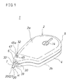
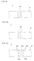
- Fig. 1 through Fig. 22 show the mark transfer tool according to the invention, and same reference numerals indicate same constituent members or elements throughout the entire drawings.
- the mark transfer tool according to this embodiment is shown in Fig. 1 to Figs. 7A-7C.
- This mark transfer tool 1 is, specifically, to transfer marks in a thin film combining characters, codes, patterns or their combination arranged and formed on a mark transfer tape T (in the shown example, only a mark composed of alphabetic letters SEED) M, M, ..., to a sheet of paper or the like, and it is a refill type having a cartridge structure allowing to exchange the mark transfer tape T as a consumable part.
- the mark transfer tool 1 comprises a case 2 having an appearance as shown in Fig. 1, and a tape cartridge C having a transfer head H as shown in Fig. 2 and Fig. 3.
- the case 2 is held and manipulated by one hand, and is a flat box having a front contour shape and dimension and width enough to incorporate the tape cartridge C, and its confronting pair of flat face and back sides 2a, 2b are standard gripping sides when holding and manipulating by one hand.
- the case 2 is a plastic structure integrally formed by injection molding or the like, and a case main body 4 and a cap body 5 are separate, and the tape cartridge is detachably inserted in the case main body 4.
- a head inserting portion 6 for inserting the transfer head H in and out is formed.
- the tape cartridge C is an exchangeable consumable part.
- the tape cartridge C consists of a pay-out reel 11 on which a mark transfer tape T is wound, and a rotatable take-up reel 12 for collecting the mark transfer tape T after use, which are rotatably installed in a cartridge case 10, and further a transfer head H for pressing and transferring the mark transfer tape to the correction area is installed rotatably about the head axial center.
- the tape cartridge C further includes a tape interlocking unit for mutually interlocking the pay-out reel 11 and take-up reel 12, a clutch mechanism for synchronizing the pay-out speed and take-up speed of the mark transfer tape T in the pay-out reel 11 and take-up reel 12, and other principal and basic components, which are assembled as a unit.
- the cartridge case 10 is made of synthetic resin in a form of a cartridge case for accommodating the both reels 11, 12, and its shape and dimensions are set to be lightweight and compact in a range of having holding functions of both reels 11, 12, and more specifically it is a skeletal structure mainly composed of thin skeletal members.
- the mark transfer tape T is to supply transfer marks M continuously, and pressure-sensitive adhesive transfer marks M are disposed and held on the surface of a base tape 15 continuously and peelably at specified intervals. Between the transfer marks M, M, division bodily sensing means 20 showing the division position of transfer marks M is disposed, and corresponding to this, at the tape traveling part of the transfer head H, a bodily sensing engaging part 21 to be engaged with the division bodily sensing means 20 is provided.
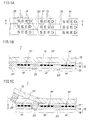
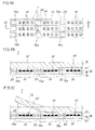
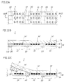
- the mark transfer tape T has a sectional structure as shown in Fig. 5, and on the surface of the base tape 15 (the lower side in Fig. 5B and Fig. 5C), a transfer mark layer 16 composed of multiple transfer marks M, M, ... is peelably adhered and held. Since the drawings are intended to help understanding, they are schematic and magnified in the thickness direction, but actually the mark transfer tape T is a thin film, and the boundary of layers is not so clear as illustrated.
- the base tape 15 has its both face and back sides processed to be peelable, that is, it is a film tape made of plastic or paper material, having the surface treated to be separable or peelable from the adjacent layers or materials, and a non-stretchable flexible film is preferably used.
- the transfer mark layer 16 is a laminate structure integrally laminating a mark forming layer 17, a mark array layer 18, and a pressure-sensitive adhesive layer 19. This transfer mark layer 16 is continuous over the overall length of the base tape 15, that is, the transfer marks M, M, ... are formed continuously, and are properly cut off by transfer operation of the transfer head H at the time of mark transfer.
- the mark forming layer 17 is intended to facilitate formation (specifically printing) of mark array layer 18, and has a function of adhering and holding the transfer mark layer 16 on the surface of the base tape 15, and a surface layer is formed after transfer of transfer mark M.
- the mark forming layer 17 is made of an adhesive transparent material. That is, the mark forming layer 17 is preferably made of a transparent see-through resin material of dry type suited to surface layer after parting, having a proper adhesion holding property on the parted surface of the base tape 15.
- the mark array layer 18 is composed of multiple marks (in the shown example, only a mark composed of alphabetic letters SEED) M', M', M', ... arranged continuously and peelable at specific intervals in the running direction of the base tape 15, and is specifically formed on the mark forming layer 17 by a known printing technology.
- the printing method of the mark array layer 18 includes various known printing techniques, specifically, typographic (relief) printing, offset printing, gravure (intaglio) printing, or silk screen printing, and further novel printing techniques such as laser printer, heattransfer, and ink jet printer systems, which may be properly selected depending on the properties of the forming object area (in the shown case, the mark forming layer 17).
- the pressure-sensitive adhesive layer 19 is used to press and adhere the transfer mark layer 16 to the correction area, and to form a surface layer of mark transfer tape T before transfer, and this pressure-sensitive adhesive layer 19 is made of a pressure-sensitive transparent material. That is, the pressure-sensitive adhesive layer 19 is preferably made of a transparent see-through adhesive material of dry type suited to a surface layer before parting, having a pressure-sensitive adhesion to the correction area.
- Such laminated transfer mark layer 16 is, as shown in Fig. 5, adhered and held on the surface (the lower side in Fig. 5B and fig. 5C) of the base tape 15 processed for parting, peelably and separably through the mark forming layer 17.
- the division bodily sensing means 20 is specifically, as shown in Fig. 5, a bodily sensing sliding part printed and formed on the surface (the lower side in Fig. 5B and Fig. 5C) of the transfer mark layer 16, and its printing method is one of various conventional printing techniques same as in the case of the mark array layer 18.
- This bodily sensing sliding part 20 is formed corresponding to the mutually adjacent transfer marks M, M of the transfer mark layer 16, and is formed, for example, by known printing process on the surface of the pressure-sensitive adhesive layer 19 in the transfer mark layer 16.
- This bodily sensing sliding part 20 has the same sliding characteristics as the parting process applied to the surface and back sides of the base tape 15, covers the surface of the pressure-sensitive adhesive layer 19 to extinguish the pressure adhesion of this portion on the correction area.
- This bodily sensing sliding part 20 is made of a transparent parting material same ass the mark forming layer 17 and pressure-sensitive adhesive layer 19.
- the specific forming position of the bodily sensing sliding part 20 is set corresponding to the bodily sensing engaging part 21 of the transfer head H, and is set so as to indicate the division position of one transfer mark M, or the transfer completion position in the shown embodiment, by bodily sensation, when the bodily sensing sliding part 20 is engaged with the bodily sensing engaging part 21 in the mark transfer operation of the mark transfer tool 1 mentioned below to cause a sliding phenomenon in the engaging position.
- the bodily sensing engaging part 21 corresponding to the bodily sensing sliding part 20 is set at the tape traveling part of the transfer head H, and the leading edge of the transfer head, that is, the leading end pressing portion 25 functions also as the bodily sensing engaging part 21.
- the mark transfer tape T paid out from the pay-out reel 11 is guided into the leading end pressing portion 25 along the tape traveling surface at one side of the transfer head H, and passes through the leading end pressing portion 25 and is inverted, and is further guided along the tape traveling surface of the opposite side, and taken up on the take-up reel 12, and as shown in Fig. 4A and Fig. 4B, the transfer completion position of one transfer mark M is indicated by bodily sensation when the bodily sensing sliding part 20 of the mark transfer tape T is engaged with the leading end pressing portion 25 (21) of the transfer head H to cause a sliding phenomenon in the engaging position.
- the mark transfer tape T in the shown embodiment is manufactured as a band having a tape width corresponding to plural mark transfer tapes T, T, ... as shown in Fig. 5A, and cut and formed in a width of one tape T by slitter or other cutting device.
- the mark forming layer 17 is applied and formed on the surface of the base tape 15
- the mark array layer 18 is printed and formed on the surface of the mark forming layer 17, and the pressure-sensitive adhesive layer 19 is applied and formed thereon, and finally the bodily sensing sliding part 20 is printed and formed on the pressure-sensitive adhesive layer 19.
- the transfer head H presses the mark transfer tape T to a correction area on a sheet of paper, and it is disposed at the leading end of the cartridge case 10, and has a function of guiding the mark transfer tape T and a function of pressing.
- a specific structure of the transfer head H comprises a head main body 30, a head holding portion 31, and a rotary operation portion 32.
- the head main body 30 is held rotatably about its axial center, that is, a so-called rotary head structure is formed.
- the head main body 30 is to press and transfer the mark transfer tape T, and is shaped to be suited to transfer accurately to a desired transfer position, that is, in a pointed form.
- the head main body 30 in the shown example is a thin plate having a rectangular shape slightly wider than the mark transfer tape T, and has a taper section, being pointed in a side view so as to be gradually thin toward the leading end.
- the head main body 30 has flat both side surfaces 30a, 30b, which form tape traveling surfaces, and a leading edge 25 is a leading end pressing portion for pressing the mark transfer tape T as mentioned above and also functions as the bodily sensing engaging part 21.
- This leading end pressing portion 25 is a straight edge orthogonal to the tape traveling direction in the tape traveling surfaces 30a, 30b.
- guide flanges 33, 33 are formed for guiding running of mark transfer tape T.
- the thickness of the plate for composing the head main body 30 is relatively small, tapering as shown in the drawing is not always necessary, but the plate thickness may be uniform throughout the longitudinal direction, and anyway the structure is not particularly specified as far as the leading end of the pressing portion of the head main body 30 has a thickness (a point) enough to position and indicate the transfer position accurately.
- a borne portion 35 is integrally formed as a main body support.
- the head holding portion 31 supports the head main body 30 rotatably bout its axial center, and specifically comprises a borne portion 35 as the main body support, and a bearing 3 6 provided in the cartridge case 10.
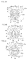
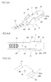
- the borne portion 35 is, as shown in Figs. 6A-6C, a cylindrical portion provided concentrically and integrally with the head main body 30, and more specifically it is formed in an arc section having a setting opening 35a of mark transfer tape T to the head main body 30 in a part thereof.
- the bearing 36 is disposed integrally at the leading end of the cartridge case 10. As shown in Figs. 6A-6C, the bearing 36 is tubular having an inner circumference corresponding to the outer circumference of the borne portion 35, and same as the borne portion 35, it is formed in an arc section having a setting opening 36a of mark transfer tape T to the head main body 30 in a part thereof.
- the born portion 35 is slidably supported on the bearing 36, and the head main body 30 is freely rotatable about the axial center in a specified rotating angle range described below.
- the rotary operation portion 32 is to determine the rotating direction position of the head main body 30, and also serves as head position indicator to show the tape pressing and transferring position of the head main body 30.
- the rotary operation portion 32 is a circular bar, and has an operation lever 45 including an operation knob 45a disposed at its leading end as a principal unit.
- the operation lever 45 is extended linearly outward in the radial direction from the axial center of the born portion 35, and projects to the outside of the case 2, through a slit inserting portion 46 and an operation guide portion 47 disposed at corresponding positions in the bearing 36 and case 2.
- the inserting portion 46 of the bearing 36 functions as a locking portion of the head main body 30 to prevent it from slipping out in the axial direction.
- the location of the operation lever 45 in the rotating direction with respect to the head main body 30 is set in relation to the tape pressing and transferring position of the head main body 30, and the slit inserting portion 46 and operation guide portion 47 are extended in the peripheral direction so as to allow moving of the operation lever 45 in the rotating direction of the head main body 30.
- the operation guide portion 47 of the case 2 defines the operating range in the rotating direction of the operation lever 45, and is configured to control the tape pressing and transferring position of the head main body 30.
- the new mark transfer tape T rolled out from the pay-out reel 11 is at the upper side of the head main body 30, and is in a state suited to use by lateral pull by a left-handed user (see Fig. 7C).
- the direction of the operation lever 45 directly and visually shows the opposite direction of the new mark transfer tape T (function as head position indicator), and the user can confirm the tape pressing and transferring position of the head main body 30 by referring to the direction of the operation lever 45.
- the rotating direction operating range of the operation guide portion 47 (nearly 180° at maximum in shown example) can be set in various desired values from a small angle range to a large angle range in consideration of relation between the operation lever 45 and the tape pressing and transferring position of the head main body 30.
- the operation lever 45 can be rotated according to the purpose, and an optimum tape pressing and transferring position of the head main body 30 of the transfer head H (typically, first defined position A shown in Fig. 6A, second defined position B shown in Fig. 6B, or third defined position C shown in Fig.
- the case 2 can be gripped by fingers on the gripping surfaces (standard gripping surfaces are face and back sides 2a, 2b of the case 2, but proper positions or sides of the case 2 may be gripped depending on the purpose), so that various methods of use, for example, as shown in Figs. 7A to 7C may be possible.
- the gripping surfaces of the case 2 are held like holding a writing tool, and the leading end pressing portion 25 of the transfer head H is pressed tightly to the transfer start end of the correction area 50 on a sheet of paper or the like, and the case 2 is moved along the sheet of paper by a specified distance and stopped.
- the transfer head H is tightly pressed to the transfer start end on the correction area 50, and the case 2 is directly moved along the sheet of paper, and is stopped when the next bodily sensing sliding part 20 is engaged with the bodily sensing engaging part 21 to cause a sliding phenomenon in the engaging position.
- the transfer mark M of the mark transfer tape T in the leading end pressing portion 25 of the transfer head is peeled from the base tape 15, and transferred onto the correction area 50, and the used mark transfer tape T after the transfer mark M is peeled off, that is, the base tape 15 is taken up and collected on the take-up reel 12.
- the portion of the transfer mark layer 16 having the bodily sensing sliding part 20 is not adhered to the correction area 50, but is left over on the base tape 15.
- the mark transfer tool 1 of the embodiment has a cartridge structure for exchanging the mark transfer tape T, various transfer marks M, M, ... depending on the purpose of use can be transferred and used by preparing a plurality of tape cartridges C having mark transfer tapes T of plural types of transfer marks M, M, ....
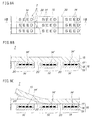
- FIGs. 8A-8C This embodiment is shown in Figs. 8A-8C, in which the structure of the mark transfer tape T in embodiment 1 is modified.
- the transfer mark layer 16 is formed continuously over the entire length of the base tape 15, whereas in the mark transfer tape T of this embodiment, as shown in Fig. 8, transfer marks M, M, ... composing the transfer mark layer 16 are peelably adhered and held on the surface of the base tape 15 independently and at specific intervals.
- the bodily sensing sliding part 20 is composed of the surface of the base tape 15 between the mutually adjacent marks M, M in the mark transfer layer 16.
- FIGs. 9A-9C This embodiment is shown in Figs. 9A-9C, in which the structure of the mark transfer tape T in embodiment 2 is modified.
- transfer marks M, M, ... composing the transfer mark layer 16 are peelably adhered and held on the surface of the base tape 15 independently and at specific intervals, and these transfer marks M, M are mutually coupled by means of a thin coupling layer 16a.
- the specific layer structure of this coupling layer 16a is same as that of the transfer mark layer 16, and is transparent.
- the transfer marks M, M are mutually coupled by means of two thin coupling layers 16a, 16a at both side edges in the width direction.
- the bodily sensing sliding part 20 is, same as in embodiment 2, composed of the surface of the base tape 15 between the mutually adjacent marks M, M in the mark transfer layer 16.
- the transfer operation is same as in embodiment 2, but the transfer start action is easier when transferring a next transfer mark M after transferring one transfer mark M.
- the remaining portion of the coupling layers 16a, 16b promotes restarting of running without causing sliding on the mark transfer tape T, so that the mark transfer action may be smoothly and securely started again.
- FIG. 10A-10C This embodiment is shown in Figs. 10A-10C and Figs. 11A-11C, in which the specific structure of the mark transfer tape T in embodiment 1 is slightly modified.
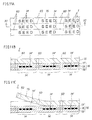
- division bodily sensing means 60 is a bodily sensing recess formed between mutually adjacent transfer marks M, M, and specifically it is a notch formed at least at one end in the width direction of the mark transfer tape T (both ends in the shown case) .
- This notch 60 formed in an arc shape (semicircular in this case) in order to prevent breakage of the base tape 15 due to stress concentration.
- a bodily sensing engaging part 61 provided in the transfer head H is a positioning bump so as to be engaged with the notch 60 in convex-concave relation.
- This positioning bump 61 is provided at both sides in the width direction of the tape traveling surface 30a of the upper side for guiding running of used mark transfer tape T, that is, the base tape 15, of the tape traveling surfaces 30a, 30b of the head main body 30 of the transfer head H.
- the positioning bump 61 is a swollen bump integrally formed simultaneously with forming of the head main body 30, and the engaging part at the leading end has an arc contour shape corresponding to the notch 60.
- the location of the positioning bump 61 is slightly behind the leading end pressing portion 25, and is at both sides in the width direction of the mark transfer tape T.
- the mark transfer tape T in this embodiment is, same as in embodiment 1, manufactured as a band having a tape width corresponding to plural mark transfer tapes T, T, ... as shown in Fig. 11A, and cut and formed in a width of one tape T by slitter or other cutting device.
- the division bodily sensing means 60 is pierced by punch or other piercing device, and therefore this division bodily sensing means 60 penetrates throughout the entire tape transfer tape T.
- FIG. 12A-12C This embodiment is shown in Figs. 12A-12C and Figs. 13A-13C, in which the specific structure of the bodily sensing recess (bodily sensing means) in embodiment 4 is slightly modified.
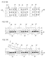
- a bodily sensing recess 70 of the embodiment is formed between mutually adjacent transfer marks M, M of the mark transfer tape T, but the notch 70 in this embodiment is tiny holes provided in the center in the width direction of the mark transfer tape T, and the tiny holes 70 are circular in order to prevent breakage of the base tape 15 due to stress concentration.
- a bodily sensing engaging part 71 provided in the transfer head H is a positioning bump so as to be engaged with the tiny hole 70 in convex-concave relation.
- This positioning bump 71 is, specifically, a swollen bump integrally formed simultaneously with forming of the head main body 30, and its contour is circular corresponding to the notch 70.
- the location of the positioning bump 71 is slightly behind the leading end pressing portion 25, and is at the central position in the width direction of the mark transfer tape T.
- FIG. 14A-14C This embodiment is shown in Figs. 14A-14C and Figs. 15A-15C, in which the specific structure of the bodily sensing recess (bodily sensing means) in embodiment 5 is slightly modified.
- a bodily sensing recess 80 of the embodiment is a concave form provided in the center of the width direction of the mark transfer tape T, but the recess 80 in this embodiment is a dent provided in the center of the width direction at the back side of the mark transfer tape T.
- This dent 80 is specifically curved from back side to surface side in part of the base tape 15, and its contour is circular.
- a bodily sensing engaging part 81 provided in the transfer head H is a positioning bump so as to be engaged with the dent 80 in convex-concave relation.
- This positioning bump 81 is, specifically, a swollen bump same as the positioning bump 71 in embodiment 5, and its contour is circular corresponding to the dent 80.
- FIG. 16A-16C This embodiment is shown in Figs. 16A-16C and Figs. 17A-17C, in which the specific structure of the mark transfer tape T in embodiment 1 is slightly modified.
- division bodily sensing means 90 is plural bodily sensing bumps formed between mutually adjacent transfer marks M, M. These bodily sensing bumps 90 are specifically two swollen formed provided on the surface (the lower side in Fig. 16B and Fig. 16C) of the transfer mark layer 16 as shown in Fig. 16.
- the leading edge of the transfer head H that is, the leading end pressing portion 25 functions also as this bodily sensing engaging part 91 (not shown).
- the specific shape and array structure of the bodily sensing bumps 90 are not limited to the examples in Figs. 16A-16C and Fig. 17A, but other configurations having similar function, as shown in Fig. 17B and Fig. 17C may be also employed.
- FIGs. 18A-18C This embodiment is shown in Figs. 18A-18C, in which the specific structure of the mark transfer tape T in embodiment 7 is slightly modified.
- division bodily sensing means 100 in this embodiment is plural bodily sensing bumps formed between mutually adjacent transfer marks M, M, but the bodily sensing bumps 100 in this embodiment are specifically two swollen formed provided on the back side (the lower side in Fig. 16B and Fig. 16C) of the transfer mark layer 16 as shown in Figs. 18A-18C.
- FIG. 19 This embodiment is shown in Fig. 19, in which the basic structure of the mark transfer tool 1 is modified.
- the mark transfer tape T as a consumable part is an exchangeable cartridge type, that is, refill type, whereas this embodiment presents a one-time disposable type, that is, all component parts including the mark transfer tape T are consumable parts.
- a transfer head H is disposed at the leading end of the case 2 so as to be rotatable about its head axial center.
- the specific structure of the transfer head H is same as in embodiment 1, except for its mounting position.
- a tape interlock unit for mutually interlocking these reels 11, 12, a clutch mechanism for synchronizing the pay-out speed and take-up speed of the mark transfer tape T by the pay-out reel 11 and take-up reel 12, and other principal and basic mechanical parts are also assembled in a unit.
- FIGs. 20A-20C This embodiment is shown in Figs. 20A-20C, in which the structure of the mark transfer tape T is modified.
- a transfer tape layer 16 to be adhered and held on the surface side (lower side in Fig. 20B and Fig. 20C) of a base tape 15 is an integral laminate structure consisting of a pressure-sensitive adhesive layer 19 and a mark array layer 18.
- the pressure-sensitive adhesive layer 19 also functions as the mark forming layer 17 in embodiment 1, and the mark array layer 18 is printed and formed on the surface of this mark forming layer 17.
- laminated transfer mark layer 16 is, as shown, adhered and held on the surface of the base tape 15 treated for parting (the lower side in Fig. 20B and Fig. 20C) peelably and separably through the pressure-sensitive adhesive layer 19.
- the bodily sensing sliding part 20 is printed and formed on the surface of the base tape 15, and the pressure-sensitive adhesive layer 19 is applied and formed on the surface of the base tape 15, and the mark array layer 18 is printed and formed on the surface of the pressure-sensitive adhesive layer 19.
- FIGs. 21A-21C This embodiment is shown in Figs. 21A-21C, in which the structure of the mark transfer tape T is modified.
- a transfer tape layer 16 to be adhered and held on the surface side (lower side in Fig. 21B, (c)) of a base tape 15 is an integral laminate structure consisting of a mark array layer 18 and a pressure-sensitive adhesive layer 19, and the mark forming layer 17 in the mark transfer tape T in embodiment 1 is omitted.
- the mark array layer 18 is directly printed and formed on the parting treated surface of the base tape 15, and when transferring a mark, therefore, the mark array layer 18 is peeled from the surface of the base tape 15, and the surface layer is formed directly.
- the other configuration and operation are same as in embodiment 1.
- FIGs. 22A-22C This embodiment is shown in Figs. 22A-22C, in which the structure of the mark transfer tape T in embodiment 10 is slightly modified.
- the surface side (lower side in Fig. 22B and Fig. 22C) of a base tape 15 is treated to be adhesive 110, and a mark array layer 18 is directly printed and formed on this surface.
- the mark array layer 18 is peeled from the surface of the base tape 15, and the surface layer is formed directly.
- the mark transfer tool of the invention is a mark transfer tool for transferring a transfer mark on a mark transfer tape on a sheet of paper or the like, and more specifically it comprises a hand-held case, a pay-out reel containing a mark transfer tape, being rotatably installed in the case, a rotatable take-up reel for collecting the used mark transfer tape, being rotatably installed in the case, and a transfer head for pressing and transferring the mark transfer tape being paid out from the pay-out reel onto the correction area, being disposed at the leading end of the case, in which the mark transfer tape has pressure-sensitive adhesive transfer marks disposed and held continuously at specific intervals peelably on the surface of a base tape, and further division bodily sensing means showing division positions of transfer marks is disposed between transfer marks, and bodily sensing engaging parts to be engaged with the division bodily sensing means of the mark transfer tape are disposed on the tape traveling area of the transfer head, and therefore it presents a novel mark transfer technology completely different from the conventional mark using technology, about various
- the case is gripped by fingers, and the leading end pressing portion of the transfer head is tightly pressed to the correction area, and is moved along the sheet of paper, so that the transfer mark is transferred.
- the transfer head With the division bodily sensing means provided in the mark transfer tape being engaged with the bodily sensing engaging part of the transfer head, the transfer head is tightly pressed to the transfer start end on the correction area, and the case is directly moved along the sheet of paper, and is stopped when the next division bodily sensing means is engaged with the bodily sensing engaging part to cause a sliding phenomenon at this engaging position or a hooking phenomenon in the traveling action of the mark transfer tape.
- the transfer mark on the mark transfer tape in the leading end pressing portion of the transfer head is peeled from the transfer head, and is precisely transferred on the correction area, and the used mark transfer tape after peeling the transfer mark, that is, the base tape is taken up and collected on the take-up reel.
Landscapes
- Adhesive Tape Dispensing Devices (AREA)
- Decoration By Transfer Pictures (AREA)
- Labeling Devices (AREA)
Applications Claiming Priority (2)
| Application Number | Priority Date | Filing Date | Title |
|---|---|---|---|
| JP2001072096A JP4620270B2 (ja) | 2001-03-14 | 2001-03-14 | マーク転写具およびマーク転写テープ |
| JP2001072096 | 2001-03-14 |
Publications (2)
| Publication Number | Publication Date |
|---|---|
| EP1241122A2 true EP1241122A2 (de) | 2002-09-18 |
| EP1241122A3 EP1241122A3 (de) | 2003-01-29 |
Family
ID=18929724
Family Applications (1)
| Application Number | Title | Priority Date | Filing Date |
|---|---|---|---|
| EP02250799A Withdrawn EP1241122A3 (de) | 2001-03-14 | 2002-02-06 | Musterübertragungsgerät und Musterübertragungsband |
Country Status (8)
| Country | Link |
|---|---|
| US (1) | US6575220B2 (de) |
| EP (1) | EP1241122A3 (de) |
| JP (1) | JP4620270B2 (de) |
| KR (1) | KR20020073243A (de) |
| CN (1) | CN100354191C (de) |
| AU (1) | AU2128702A (de) |
| CA (1) | CA2369922A1 (de) |
| HK (1) | HK1049319A1 (de) |
Cited By (2)
| Publication number | Priority date | Publication date | Assignee | Title |
|---|---|---|---|---|
| EP1323657A3 (de) * | 2001-12-27 | 2004-06-30 | Dynic Corporation | Musterübertragungsgerät, Musterübertragungsband und Herstellungsverfahren dafür |
| WO2018172388A1 (de) * | 2017-03-22 | 2018-09-27 | Tesa Se | Applikator für stanzlinge |
Families Citing this family (10)
| Publication number | Priority date | Publication date | Assignee | Title |
|---|---|---|---|---|
| JP2002337831A (ja) * | 2001-05-21 | 2002-11-27 | Seed:Kk | マーク転写具およびマーク転写テープ |
| US6997229B2 (en) * | 2003-09-16 | 2006-02-14 | Sanford, L.P. | Rotatable applicator tip for a corrective tape dispenser |
| JP4644840B2 (ja) * | 2005-04-27 | 2011-03-09 | コクヨ株式会社 | カバーの係止構造及び転写具 |
| US8397784B2 (en) | 2010-08-31 | 2013-03-19 | Sanford, L.P. | Correction tape dispenser with variable clutch mechanism |
| US8746313B2 (en) | 2010-12-29 | 2014-06-10 | Sanford, L.P. | Correction tape re-tensioning mechanism and correction tape dispenser comprising same |
| US8578999B2 (en) | 2010-12-29 | 2013-11-12 | Sanford, L.P. | Variable clutch mechanism and correction tape dispenser with variable clutch mechanism |
| US8746316B2 (en) | 2011-12-30 | 2014-06-10 | Sanford, L.P. | Variable clutch mechanism and correction tape dispenser with variable clutch mechanism |
| CN103738088B (zh) * | 2014-01-14 | 2016-01-13 | 广东乐普升文具有限公司 | 一种涂改压头及含有这种涂改压头的修正带 |
| CN107812326B (zh) * | 2017-11-27 | 2023-06-20 | 上海市肺科医院 | 一种医用放疗定位标记装置及标定方法 |
| CN111717442B (zh) * | 2020-05-21 | 2025-04-04 | 深圳市久巨工业设备有限公司 | 压合机构及包装机 |
Family Cites Families (16)
| Publication number | Priority date | Publication date | Assignee | Title |
|---|---|---|---|---|
| US4525237A (en) * | 1982-05-24 | 1985-06-25 | Leonard S. Blondes | Method of reinforcing loose-leaf sheets and disposable reinforcing tab applicator therefor |
| JPS5959490A (ja) * | 1982-09-30 | 1984-04-05 | Oudenshiya:Kk | マ−ク転写方法 |
| JPS59135184A (ja) * | 1983-01-24 | 1984-08-03 | Shoichi Yamada | マ−ク転写法 |
| US4718971A (en) * | 1986-10-09 | 1988-01-12 | Moore Push-Pin Company | Dispenser for a transfer adhesive |
| US4880490A (en) * | 1987-10-13 | 1989-11-14 | Macintyre B Stuart | Adhesive backed element applicator |
| US5061947A (en) * | 1988-06-22 | 1991-10-29 | Monarch Marking Systems, Inc. | Microprocessor controlled thermal printer |
| JPH04110200A (ja) * | 1990-08-30 | 1992-04-10 | Marujiyuu Kasei Kk | 文字修正用ラベルテープと該ラベルの繰り出し装置 |
| US5824379A (en) * | 1995-12-11 | 1998-10-20 | Monarch Marking Systems, Inc. | Composite label web |
| JPH1016414A (ja) * | 1996-07-05 | 1998-01-20 | Casio Comput Co Ltd | インクリボン |
| JP3296265B2 (ja) * | 1997-09-12 | 2002-06-24 | 株式会社シード | 塗膜転写具のクラッチ機構および塗膜転写具 |
| US6029849A (en) * | 1997-09-23 | 2000-02-29 | Meshulam; Eli | Paperbacked stamp dispenser |
| US6177163B1 (en) * | 1998-06-22 | 2001-01-23 | Tricor Direct, Inc. | Markable repositionable adhesive sheet dispensing roll for use in an industrial setting |
| US6394165B1 (en) * | 1998-11-09 | 2002-05-28 | Steven M. Rader | Self-adhesive element dispenser and applicator device and method thereof |
| JP2001018587A (ja) * | 1999-07-06 | 2001-01-23 | Seed Rubber Kogyo Kk | 塗膜転写用ヘッド装置および塗膜転写具 |
| JP2002234517A (ja) * | 2001-02-07 | 2002-08-20 | Seed:Kk | マーク転写具およびマーク転写テープ |
| US20020179242A1 (en) * | 2001-05-03 | 2002-12-05 | Wien Thomas M. | Methods and apparatus for dispensing labels and label strips for use in the same |
-
2001
- 2001-03-14 JP JP2001072096A patent/JP4620270B2/ja not_active Expired - Fee Related
- 2001-12-21 US US10/024,308 patent/US6575220B2/en not_active Expired - Lifetime
- 2001-12-28 KR KR1020010086816A patent/KR20020073243A/ko not_active Withdrawn
- 2001-12-31 CN CNB011453036A patent/CN100354191C/zh not_active Expired - Fee Related
-
2002
- 2002-01-25 CA CA002369922A patent/CA2369922A1/en not_active Abandoned
- 2002-02-06 EP EP02250799A patent/EP1241122A3/de not_active Withdrawn
- 2002-03-07 AU AU21287/02A patent/AU2128702A/en not_active Abandoned
-
2003
- 2003-02-20 HK HK03101295.7A patent/HK1049319A1/en unknown
Cited By (2)
| Publication number | Priority date | Publication date | Assignee | Title |
|---|---|---|---|---|
| EP1323657A3 (de) * | 2001-12-27 | 2004-06-30 | Dynic Corporation | Musterübertragungsgerät, Musterübertragungsband und Herstellungsverfahren dafür |
| WO2018172388A1 (de) * | 2017-03-22 | 2018-09-27 | Tesa Se | Applikator für stanzlinge |
Also Published As
| Publication number | Publication date |
|---|---|
| US6575220B2 (en) | 2003-06-10 |
| CN100354191C (zh) | 2007-12-12 |
| AU2128702A (en) | 2002-09-19 |
| HK1049319A1 (en) | 2003-05-09 |
| JP4620270B2 (ja) | 2011-01-26 |
| CA2369922A1 (en) | 2002-09-14 |
| US20020129719A1 (en) | 2002-09-19 |
| CN1374243A (zh) | 2002-10-16 |
| EP1241122A3 (de) | 2003-01-29 |
| JP2002264596A (ja) | 2002-09-18 |
| KR20020073243A (ko) | 2002-09-23 |
Similar Documents
| Publication | Publication Date | Title |
|---|---|---|
| US6595260B2 (en) | Mark transfer tool and mark transfer tape | |
| US6575220B2 (en) | Mark transfer tool and mark transfer tape | |
| US6769470B2 (en) | Mark transfer tool and mark transfer tape | |
| EP1266855A2 (de) | Musterübertragungsgerät und Musterübertragungsband | |
| US7178573B2 (en) | Mark transfer tool, mark transfer tape, and manufacturing method of mark transfer tape | |
| US6681827B2 (en) | Mark transfer tool and mark transfer tape | |
| EP1743779B1 (de) | Übertragungswerkzeug | |
| EP1380527A1 (de) | Markierungsübertragungsgerät und Markierungsübertragungsband | |
| JP4106829B2 (ja) | アタッチメント | |
| HK1056862A (en) | Mark transfer tool, mark transfer tape and manufacturing method of mark transfer tape |
Legal Events
| Date | Code | Title | Description |
|---|---|---|---|
| PUAI | Public reference made under article 153(3) epc to a published international application that has entered the european phase |
Free format text: ORIGINAL CODE: 0009012 |
|
| AK | Designated contracting states |
Kind code of ref document: A2 Designated state(s): AT BE CH CY DE DK ES FI FR GB GR IE IT LI LU MC NL PT SE TR |
|
| AX | Request for extension of the european patent |
Free format text: AL;LT;LV;MK;RO;SI |
|
| PUAL | Search report despatched |
Free format text: ORIGINAL CODE: 0009013 |
|
| AK | Designated contracting states |
Designated state(s): AT BE CH CY DE DK ES FI FR GB GR IE IT LI LU MC NL PT SE TR |
|
| AX | Request for extension of the european patent |
Extension state: AL LT LV MK RO SI |
|
| 17P | Request for examination filed |
Effective date: 20030422 |
|
| AKX | Designation fees paid |
Designated state(s): DE ES FR GB IT NL |
|
| REG | Reference to a national code |
Ref country code: HK Ref legal event code: WD Ref document number: 1049319 Country of ref document: HK |
|
| GRAP | Despatch of communication of intention to grant a patent |
Free format text: ORIGINAL CODE: EPIDOSNIGR1 |
|
| STAA | Information on the status of an ep patent application or granted ep patent |
Free format text: STATUS: THE APPLICATION IS DEEMED TO BE WITHDRAWN |
|
| 18D | Application deemed to be withdrawn |
Effective date: 20100218 |