EP1241309A2 - Dispositif de coulissement pour portes d'ascenseur - Google Patents
Dispositif de coulissement pour portes d'ascenseur Download PDFInfo
- Publication number
- EP1241309A2 EP1241309A2 EP01130522A EP01130522A EP1241309A2 EP 1241309 A2 EP1241309 A2 EP 1241309A2 EP 01130522 A EP01130522 A EP 01130522A EP 01130522 A EP01130522 A EP 01130522A EP 1241309 A2 EP1241309 A2 EP 1241309A2
- Authority
- EP
- European Patent Office
- Prior art keywords
- door
- bearing
- sliding
- rail
- linear
- Prior art date
- Legal status (The legal status is an assumption and is not a legal conclusion. Google has not performed a legal analysis and makes no representation as to the accuracy of the status listed.)
- Granted
Links
Images

Classifications
-
- E—FIXED CONSTRUCTIONS
- E05—LOCKS; KEYS; WINDOW OR DOOR FITTINGS; SAFES
- E05D—HINGES OR SUSPENSION DEVICES FOR DOORS, WINDOWS OR WINGS
- E05D15/00—Suspension arrangements for wings
- E05D15/06—Suspension arrangements for wings for wings sliding horizontally more or less in their own plane
- E05D15/0621—Details, e.g. suspension or supporting guides
- E05D15/0626—Details, e.g. suspension or supporting guides for wings suspended at the top
- E05D15/0643—Details, e.g. suspension or supporting guides for wings suspended at the top on balls or floating rollers
-
- E—FIXED CONSTRUCTIONS
- E05—LOCKS; KEYS; WINDOW OR DOOR FITTINGS; SAFES
- E05D—HINGES OR SUSPENSION DEVICES FOR DOORS, WINDOWS OR WINGS
- E05D15/00—Suspension arrangements for wings
- E05D15/06—Suspension arrangements for wings for wings sliding horizontally more or less in their own plane
- E05D15/0621—Details, e.g. suspension or supporting guides
- E05D15/0626—Details, e.g. suspension or supporting guides for wings suspended at the top
- E05D15/0647—Details, e.g. suspension or supporting guides for wings suspended at the top on sliding blocks
-
- E—FIXED CONSTRUCTIONS
- E05—LOCKS; KEYS; WINDOW OR DOOR FITTINGS; SAFES
- E05Y—INDEXING SCHEME ASSOCIATED WITH SUBCLASSES E05D AND E05F, RELATING TO CONSTRUCTION ELEMENTS, ELECTRIC CONTROL, POWER SUPPLY, POWER SIGNAL OR TRANSMISSION, USER INTERFACES, MOUNTING OR COUPLING, DETAILS, ACCESSORIES, AUXILIARY OPERATIONS NOT OTHERWISE PROVIDED FOR, APPLICATION THEREOF
- E05Y2900/00—Application of doors, windows, wings or fittings thereof
- E05Y2900/10—Application of doors, windows, wings or fittings thereof for buildings or parts thereof
- E05Y2900/104—Application of doors, windows, wings or fittings thereof for buildings or parts thereof for elevators
Definitions
- This invention relates to a sliding device for elevator doors.
- this invention relates to a sliding device for elevator doors opening from the side or in the middle, which sliding device can be fitted in the region of the upper and/or lower guide of a door.
- the doors of elevators consist of one or a plurality of door leaves which, for opening and closing, are slidably displaced on suitable, horizontally extending guides.
- a first guide is arranged, which generally consists of two sliding fits, arranged one above the other, for one holding element of the door leaf or of the door leaves.
- a second guide or sliding rail for the door leaf or the door leaves is inserted.
- This guide consists conventionally of metal profiles, which are provided with one or a plurality of horizontally extending recesses which are suitable for receiving conventional plastic or metal rollers. On these rollers, when being opened and closed, the door leaves are displaced by an electric motor which belongs to the drive unit of the control part.
- rollers have the unavoidable tendency to wear, sometimes even unevenly, causing the precision of the movement when opening and closing the door leaves to suffer.
- the resultant play cannot be removed and further an undesired noisiness of the general arrangement arises, which results in complicated replacement work becoming necessary.
- rollers have constructional limitations regarding the supporting capacity of loads.
- over-dimensioned rollers have to be provided, resulting in an increased spatial requirement.
- the present invention has the object of removing the above mentioned disadvantages.
- this invention has the object of providing a sliding device for elevator doors, wherein the members which render possible the movement of the door leaves along the guides, guarantee a constant, precise movement and prevent advancing signs of deterioration.
- a further object of this invention is to provide a device as described above which is suitable for still rendering it possible for this movement to be noiseless even after opening and closing of the door leaves many times.
- this invention has the object of providing a device suitable for sustaining considerable loads without demanding an increased spatial requirement.
- this invention has the object of making available a sliding device for elevator doors which can guarantee long durability and reliability and further can be simply and economically manufactured.
- a sliding device for elevator doors which can be fitted in the region of the upper and/or lower guide, which is arranged in the region of one or both of the upper and/or lower guides for the movement of opening and closing of the door leaves, and is essentially characterized in that it consists of at least one linear sliding bearing or a ball bearing.
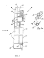
- a leaf 10 of an elevator door is limited below along the entrance side (see arrow) of the elevator space (not shown) by a door sill 12 consisting of a conventional, horizontally extending profiled metal.
- the door leaf 10 is connected at its opposite, upper end with a per se known drive unit 14.
- the upper sliding guide 18 for the door leaf or door leaves is fixedly joined to a supporting structure 16 of the door, which supporting structure is fixed on a frame 17 of the door.
- This guide 18, which consists of an elongated bar of metal or another suitable material, has at least one longitudinal rib 20, which forms a guiding rail for the sliding device according to the invention.
- the guide 18 has preferably two longitudinal ribs 20 located opposite one another, which are aligned towards one another in a vertical direction, have an essentially semicircular, convex profile, and are arranged on the upper and lower side of the guide 18.
- the sliding device comprises one or a plurality of linear sliding bearings 22 or ball bearings, the surface of which facing the respective rib 20 has a complementary semicircular, concave profile.
- linear sliding bearings 22 are fitted by means of conventional bolts 13 to a carriage 11, which is connected with the door leaf 10.
- Fig. 1a shows in more detail the guide 18 provided with longitudinal ribs 20 on the upper and lower side and a linear sliding bearing 22.
- the carriage is fitted with four bearings of the type with recirculating balls or sliding bearings i.e. by using a type of self lubricating plastic material as it is shown in Figure 1a.
- At least one analogue sliding device is preferably arranged in the region of the door sill 12.
- a linear sliding bearing 22' is operatively joined to the door leaf or the door leaves 10 by means of one or a plurality of plate-shaped supporting elements 24 or equivalent means.
- the door sill 12 which consists, for example, of a profiled metal part with an essentially U-shaped cross section, has an elongated rib 20' which extends inwardly starting from the upper horizontal leg of the profiled sill 12 and forms the lower sliding guide or rail for the door leaf.
- Analogue to the rib 20 of the guide 18, this rib 20' has an essentially semicircular profile, that is, a profile with a complementary shape to that of the front of the linear sliding bearing 22', which abuts hereon.
- the device according to the invention can, for example, be used only in the region of the upper or of the lower sliding guide, in connection with sliding blocks of self lubricating plastic material or with ball bearings of the type with recirculating balls which are arranged functionally along the other guide.
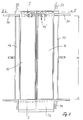
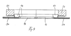
- Figs. 2 to 4 show another embodiment according to the present invention.
- Fig. 3a shows in detail a bearing rail 30 which has a U-shaped cross section and is fixed by screws 31 in a recess 32 on the upper horizontal part of the frame 17 of the door. Adjacent to the upper end of the door leaf 10 a guiding rail 33 is fastened by means of screw bolts 34.
- This guiding rail 33 extends along the width of the door leaf 10, whereas the bearing rail 30 extends laterally over the width of the door corresponding to the movement of the door leaf when opening as shown in Fig. 2.
- Both legs of the U-shaped bearing rail 30 are provided on the inner side with a runway for balls 35 which runway has in cross section a concave form corresponding to the radius of the balls 35.
- the upper and lower side of the guiding rail 33 is provided with a runway for the balls 35, which balls 35 are guided in a cage 36 extending essentially along the guiding rail 33.
- the cage 36 is connected with the guiding rail 33, so that the position of the plurality of balls 35 is maintained in relation to the guiding rail 33 by means of the cage 36.
- the sliding device on the lower side of the door leaf 10 comprises an elongated rib 40 which is provided directly on the lower side of the door leaf 10.
- This rib 40 is guided between inwardly bent ends 41 of the legs of a U-shaped guiding rail 42 which is inserted in the door sill in such a way that the upper edge of the guiding rail 42 is aligned with the plane of the floor as shown in Fig. 3.
- the rib 40 is not a load bearing element, but only a guiding element for the door leaf 10.
- the frame 17 of the door is fastened by means of brackets 50 on the wall 51 of a building or the like.
- 52 is a cover piece of metal sheet provided as usual in an elevator shaft.
- Figs. 2 and 3 show on the upper part of the door leaves 10 elements of a usual door locking device 14'.
- the linear sliding bearing according to Figs. 3 and 3a has the advantage of an overall reduced number of parts, wherein the sliding device can be directly mounted to the door header 17 and connected to the door panels or door leaves directly, avoiding fitting on door carriages. Further, the overall dimensions of the sliding device are reduced in relation to the embodiment of Fig. 1.
- the maintenance of the device will be reduced as well as the installation time.
- the door stability at slow and high speed is improved by multiple points of contact at the guiding rail.
- the noise level is reduced to a minimum.
- the weight of the sliding device is reduced remarkably, and the device can be manufactured very quickly.
Landscapes
- Engineering & Computer Science (AREA)
- Mechanical Engineering (AREA)
- Elevator Door Apparatuses (AREA)
- Power-Operated Mechanisms For Wings (AREA)
- Support Devices For Sliding Doors (AREA)
Applications Claiming Priority (2)
| Application Number | Priority Date | Filing Date | Title |
|---|---|---|---|
| IT2001MI000145U ITMI20010145U1 (it) | 2001-03-15 | 2001-03-15 | Dispositivo di scorrimento per ante di ascensori |
| ITMI010145U | 2001-03-15 |
Publications (3)
| Publication Number | Publication Date |
|---|---|
| EP1241309A2 true EP1241309A2 (fr) | 2002-09-18 |
| EP1241309A3 EP1241309A3 (fr) | 2005-06-15 |
| EP1241309B1 EP1241309B1 (fr) | 2008-04-09 |
Family
ID=11446613
Family Applications (1)
| Application Number | Title | Priority Date | Filing Date |
|---|---|---|---|
| EP01130522A Expired - Lifetime EP1241309B1 (fr) | 2001-03-15 | 2001-12-21 | Dispositif de coulissement pour portes d'ascenseur |
Country Status (5)
| Country | Link |
|---|---|
| EP (1) | EP1241309B1 (fr) |
| AT (1) | ATE391826T1 (fr) |
| DE (2) | DE10117735A1 (fr) |
| ES (1) | ES2302711T3 (fr) |
| IT (1) | ITMI20010145U1 (fr) |
Cited By (1)
| Publication number | Priority date | Publication date | Assignee | Title |
|---|---|---|---|---|
| US11427442B2 (en) * | 2019-03-25 | 2022-08-30 | Fujitec Co., Ltd. | Anti-falling device for elevator door |
Families Citing this family (1)
| Publication number | Priority date | Publication date | Assignee | Title |
|---|---|---|---|---|
| CN108821074A (zh) * | 2018-08-01 | 2018-11-16 | 杭州法维莱科技有限公司 | 一种单导轨双折层门装置 |
Family Cites Families (10)
| Publication number | Priority date | Publication date | Assignee | Title |
|---|---|---|---|---|
| GB594721A (en) * | 1945-03-29 | 1947-11-18 | Lockerbie & Wilkinson Birmingh | Improvements in sliding door gear |
| US1461249A (en) * | 1921-06-11 | 1923-07-10 | Oscar P Mcgee | Elevator-door hanger |
| US1568270A (en) * | 1922-08-26 | 1926-01-05 | Mccabe Hanger Mfg Co | Door hanger |
| US1650435A (en) * | 1925-11-07 | 1927-11-22 | Tyler Co W S | Door hanger |
| US1832203A (en) * | 1927-06-25 | 1931-11-17 | Grant Elevator Equipment Corp | Door hanger |
| GB1000916A (en) * | 1963-02-21 | 1965-08-11 | Clive Invest Pty Ltd | Rail construction and hanger panel carriers |
| US3615144A (en) * | 1969-12-03 | 1971-10-26 | Gordon J Plemeng | Hanger and track for sliding doors and the like |
| FR2685313B1 (fr) * | 1991-12-20 | 1994-04-08 | Otis Elevator Cy | Dispositif de fixation d'un patin de guidage de la partie inferieure d'une porte coulissante d'ascenseur. |
| DE4420646C2 (de) * | 1994-06-14 | 2002-10-10 | Thyssen Aufzugswerke Gmbh | Führungsanordnung für Schiebetüren, insbesondere Aufzugstüren |
| GB2326662B (en) * | 1997-06-24 | 2002-03-13 | Stephen Kenneth Brunton | Lift door |
-
2001
- 2001-03-15 IT IT2001MI000145U patent/ITMI20010145U1/it unknown
- 2001-04-09 DE DE10117735A patent/DE10117735A1/de not_active Withdrawn
- 2001-12-21 AT AT01130522T patent/ATE391826T1/de active
- 2001-12-21 EP EP01130522A patent/EP1241309B1/fr not_active Expired - Lifetime
- 2001-12-21 ES ES01130522T patent/ES2302711T3/es not_active Expired - Lifetime
- 2001-12-21 DE DE60133530T patent/DE60133530T2/de not_active Expired - Lifetime
Cited By (1)
| Publication number | Priority date | Publication date | Assignee | Title |
|---|---|---|---|---|
| US11427442B2 (en) * | 2019-03-25 | 2022-08-30 | Fujitec Co., Ltd. | Anti-falling device for elevator door |
Also Published As
| Publication number | Publication date |
|---|---|
| DE60133530T2 (de) | 2009-06-10 |
| DE10117735A1 (de) | 2002-10-31 |
| ATE391826T1 (de) | 2008-04-15 |
| ITMI20010145V0 (it) | 2001-03-15 |
| ES2302711T3 (es) | 2008-08-01 |
| ITMI20010145U1 (it) | 2002-09-16 |
| DE60133530D1 (de) | 2008-05-21 |
| EP1241309B1 (fr) | 2008-04-09 |
| EP1241309A3 (fr) | 2005-06-15 |
Similar Documents
| Publication | Publication Date | Title |
|---|---|---|
| EP0709337B1 (fr) | Traverse supérieur de support pour une porte d'ascenseur et pour un mécanisme de porte | |
| EP2500225A1 (fr) | Barrière automatique de quai de gare | |
| SE448562B (sv) | Sjutdorranordning for tillslutning av en oppning i en vegg | |
| KR102902233B1 (ko) | 높이 조정부를 갖는 캐리지 및 이러한 캐리지를 갖는 윈도우 또는 도어 | |
| US7424935B1 (en) | Elevator door assembly | |
| EP1241309A2 (fr) | Dispositif de coulissement pour portes d'ascenseur | |
| US20050217941A1 (en) | Equipment for fine positioning of a car of a multi-stage car | |
| US5887681A (en) | Multifunction connection and support element in a mechanism for automatic door motion for lifts and elevators | |
| US8272481B2 (en) | Guide assembly for at least one elevator door | |
| US20230383583A1 (en) | Pressing device for a window or a door | |
| JPH10175787A (ja) | エレベーターのドアー装置 | |
| KR20050035068A (ko) | 승강-활주식 문 또는 창문용 부속 장치와 그러한 부속장치의 활주체 | |
| EP2129854B1 (fr) | Système de porte coulissante | |
| CN119343502A (zh) | 带有可横向停放的扇的无障碍滑动门 | |
| EP2965676B1 (fr) | Dispositif pour une séparation de douche avec un système de porte coulissante | |
| KR102191980B1 (ko) | 자동 슬라이딩 도어 | |
| KR100512253B1 (ko) | 미닫이문 | |
| KR102465794B1 (ko) | 디스플레이 패널 제조 설비 설치 및 유지보수용 리프트 | |
| KR200332006Y1 (ko) | 미닫이문의 롤러장치 | |
| DE10132161C2 (de) | Aufzugtüranordnung und Türtafel dafür | |
| CN110461754B (zh) | 电梯的出入口装置 | |
| US12024399B2 (en) | Guiding device for an elevator door leaf | |
| KR100434406B1 (ko) | 엘리베이터의 도어 안내장치 | |
| KR102667905B1 (ko) | 미닫이용 소음 방지시스템 | |
| EP3847120B1 (fr) | Dispositif de fixation d'une traverse dans une installation d'ascenseur |
Legal Events
| Date | Code | Title | Description |
|---|---|---|---|
| PUAI | Public reference made under article 153(3) epc to a published international application that has entered the european phase |
Free format text: ORIGINAL CODE: 0009012 |
|
| AK | Designated contracting states |
Kind code of ref document: A2 Designated state(s): AT BE CH CY DE DK ES FI FR GB GR IE IT LI LU MC NL PT SE TR |
|
| AX | Request for extension of the european patent |
Free format text: AL;LT;LV;MK;RO;SI |
|
| PUAL | Search report despatched |
Free format text: ORIGINAL CODE: 0009013 |
|
| AK | Designated contracting states |
Kind code of ref document: A3 Designated state(s): AT BE CH CY DE DK ES FI FR GB GR IE IT LI LU MC NL PT SE TR |
|
| AX | Request for extension of the european patent |
Extension state: AL LT LV MK RO SI |
|
| 17P | Request for examination filed |
Effective date: 20051215 |
|
| AKX | Designation fees paid |
Designated state(s): AT BE CH CY DE DK ES FI FR GB GR IE IT LI LU MC NL PT SE TR |
|
| 17Q | First examination report despatched |
Effective date: 20060118 |
|
| GRAP | Despatch of communication of intention to grant a patent |
Free format text: ORIGINAL CODE: EPIDOSNIGR1 |
|
| GRAS | Grant fee paid |
Free format text: ORIGINAL CODE: EPIDOSNIGR3 |
|
| GRAA | (expected) grant |
Free format text: ORIGINAL CODE: 0009210 |
|
| AK | Designated contracting states |
Kind code of ref document: B1 Designated state(s): AT BE CH CY DE DK ES FI FR GB GR IE IT LI LU MC NL PT SE TR |
|
| REG | Reference to a national code |
Ref country code: GB Ref legal event code: FG4D |
|
| REG | Reference to a national code |
Ref country code: CH Ref legal event code: EP |
|
| REG | Reference to a national code |
Ref country code: IE Ref legal event code: FG4D |
|
| REF | Corresponds to: |
Ref document number: 60133530 Country of ref document: DE Date of ref document: 20080521 Kind code of ref document: P |
|
| REG | Reference to a national code |
Ref country code: ES Ref legal event code: FG2A Ref document number: 2302711 Country of ref document: ES Kind code of ref document: T3 |
|
| NLV1 | Nl: lapsed or annulled due to failure to fulfill the requirements of art. 29p and 29m of the patents act | ||
| PG25 | Lapsed in a contracting state [announced via postgrant information from national office to epo] |
Ref country code: PT Free format text: LAPSE BECAUSE OF FAILURE TO SUBMIT A TRANSLATION OF THE DESCRIPTION OR TO PAY THE FEE WITHIN THE PRESCRIBED TIME-LIMIT Effective date: 20080909 Ref country code: FI Free format text: LAPSE BECAUSE OF FAILURE TO SUBMIT A TRANSLATION OF THE DESCRIPTION OR TO PAY THE FEE WITHIN THE PRESCRIBED TIME-LIMIT Effective date: 20080409 Ref country code: NL Free format text: LAPSE BECAUSE OF FAILURE TO SUBMIT A TRANSLATION OF THE DESCRIPTION OR TO PAY THE FEE WITHIN THE PRESCRIBED TIME-LIMIT Effective date: 20080409 |
|
| EN | Fr: translation not filed | ||
| PG25 | Lapsed in a contracting state [announced via postgrant information from national office to epo] |
Ref country code: SE Free format text: LAPSE BECAUSE OF FAILURE TO SUBMIT A TRANSLATION OF THE DESCRIPTION OR TO PAY THE FEE WITHIN THE PRESCRIBED TIME-LIMIT Effective date: 20080709 Ref country code: DK Free format text: LAPSE BECAUSE OF FAILURE TO SUBMIT A TRANSLATION OF THE DESCRIPTION OR TO PAY THE FEE WITHIN THE PRESCRIBED TIME-LIMIT Effective date: 20080409 |
|
| PLBE | No opposition filed within time limit |
Free format text: ORIGINAL CODE: 0009261 |
|
| STAA | Information on the status of an ep patent application or granted ep patent |
Free format text: STATUS: NO OPPOSITION FILED WITHIN TIME LIMIT |
|
| PG25 | Lapsed in a contracting state [announced via postgrant information from national office to epo] |
Ref country code: BE Free format text: LAPSE BECAUSE OF FAILURE TO SUBMIT A TRANSLATION OF THE DESCRIPTION OR TO PAY THE FEE WITHIN THE PRESCRIBED TIME-LIMIT Effective date: 20080409 |
|
| ET | Fr: translation filed | ||
| REG | Reference to a national code |
Ref country code: FR Ref legal event code: EERR Free format text: CORRECTION DE BOPI 09/05 - BREVETS EUROPEENS DONT LA TRADUCTION N A PAS ETE REMISE A L INPI. IL Y A LIEU DE SUPPRIMER : LA MENTION DE LA NON-REMISE. LA REMISE DE LA TRADUCTION EST PUBLIEE DANS LE PRESENT BOPI. |
|
| 26N | No opposition filed |
Effective date: 20090112 |
|
| PG25 | Lapsed in a contracting state [announced via postgrant information from national office to epo] |
Ref country code: MC Free format text: LAPSE BECAUSE OF NON-PAYMENT OF DUE FEES Effective date: 20081231 |
|
| REG | Reference to a national code |
Ref country code: CH Ref legal event code: PL |
|
| PG25 | Lapsed in a contracting state [announced via postgrant information from national office to epo] |
Ref country code: CY Free format text: LAPSE BECAUSE OF FAILURE TO SUBMIT A TRANSLATION OF THE DESCRIPTION OR TO PAY THE FEE WITHIN THE PRESCRIBED TIME-LIMIT Effective date: 20080409 |
|
| PG25 | Lapsed in a contracting state [announced via postgrant information from national office to epo] |
Ref country code: LI Free format text: LAPSE BECAUSE OF NON-PAYMENT OF DUE FEES Effective date: 20081231 Ref country code: IE Free format text: LAPSE BECAUSE OF NON-PAYMENT OF DUE FEES Effective date: 20081222 Ref country code: CH Free format text: LAPSE BECAUSE OF NON-PAYMENT OF DUE FEES Effective date: 20081231 |
|
| PG25 | Lapsed in a contracting state [announced via postgrant information from national office to epo] |
Ref country code: LU Free format text: LAPSE BECAUSE OF NON-PAYMENT OF DUE FEES Effective date: 20081221 |
|
| PG25 | Lapsed in a contracting state [announced via postgrant information from national office to epo] |
Ref country code: TR Free format text: LAPSE BECAUSE OF FAILURE TO SUBMIT A TRANSLATION OF THE DESCRIPTION OR TO PAY THE FEE WITHIN THE PRESCRIBED TIME-LIMIT Effective date: 20080409 |
|
| PG25 | Lapsed in a contracting state [announced via postgrant information from national office to epo] |
Ref country code: GR Free format text: LAPSE BECAUSE OF FAILURE TO SUBMIT A TRANSLATION OF THE DESCRIPTION OR TO PAY THE FEE WITHIN THE PRESCRIBED TIME-LIMIT Effective date: 20080710 |
|
| REG | Reference to a national code |
Ref country code: FR Ref legal event code: PLFP Year of fee payment: 15 |
|
| REG | Reference to a national code |
Ref country code: FR Ref legal event code: PLFP Year of fee payment: 16 |
|
| REG | Reference to a national code |
Ref country code: FR Ref legal event code: PLFP Year of fee payment: 17 |
|
| PGFP | Annual fee paid to national office [announced via postgrant information from national office to epo] |
Ref country code: FR Payment date: 20201228 Year of fee payment: 20 Ref country code: AT Payment date: 20201218 Year of fee payment: 20 Ref country code: IT Payment date: 20201207 Year of fee payment: 20 Ref country code: GB Payment date: 20201223 Year of fee payment: 20 |
|
| PGFP | Annual fee paid to national office [announced via postgrant information from national office to epo] |
Ref country code: ES Payment date: 20210105 Year of fee payment: 20 Ref country code: DE Payment date: 20201229 Year of fee payment: 20 |
|
| REG | Reference to a national code |
Ref country code: DE Ref legal event code: R071 Ref document number: 60133530 Country of ref document: DE |
|
| REG | Reference to a national code |
Ref country code: GB Ref legal event code: PE20 Expiry date: 20211220 |
|
| PG25 | Lapsed in a contracting state [announced via postgrant information from national office to epo] |
Ref country code: GB Free format text: LAPSE BECAUSE OF EXPIRATION OF PROTECTION Effective date: 20211220 |
|
| REG | Reference to a national code |
Ref country code: AT Ref legal event code: MK07 Ref document number: 391826 Country of ref document: AT Kind code of ref document: T Effective date: 20211221 |
|
| REG | Reference to a national code |
Ref country code: ES Ref legal event code: FD2A Effective date: 20220405 |
|
| PG25 | Lapsed in a contracting state [announced via postgrant information from national office to epo] |
Ref country code: ES Free format text: LAPSE BECAUSE OF EXPIRATION OF PROTECTION Effective date: 20211222 |