EP1241415A2 - Heizkörper mit einer mittig angeordneten Ventilgarnitur - Google Patents
Heizkörper mit einer mittig angeordneten Ventilgarnitur Download PDFInfo
- Publication number
- EP1241415A2 EP1241415A2 EP02090034A EP02090034A EP1241415A2 EP 1241415 A2 EP1241415 A2 EP 1241415A2 EP 02090034 A EP02090034 A EP 02090034A EP 02090034 A EP02090034 A EP 02090034A EP 1241415 A2 EP1241415 A2 EP 1241415A2
- Authority
- EP
- European Patent Office
- Prior art keywords
- radiator
- radiator according
- longitudinal channel
- connecting pieces
- front plate
- Prior art date
- Legal status (The legal status is an assumption and is not a legal conclusion. Google has not performed a legal analysis and makes no representation as to the accuracy of the status listed.)
- Granted
Links
Images

Classifications
-
- F—MECHANICAL ENGINEERING; LIGHTING; HEATING; WEAPONS; BLASTING
- F24—HEATING; RANGES; VENTILATING
- F24D—DOMESTIC- OR SPACE-HEATING SYSTEMS, e.g. CENTRAL HEATING SYSTEMS; DOMESTIC HOT-WATER SUPPLY SYSTEMS; ELEMENTS OR COMPONENTS THEREFOR
- F24D19/00—Details
- F24D19/0002—Means for connecting central heating radiators to circulation pipes
-
- F—MECHANICAL ENGINEERING; LIGHTING; HEATING; WEAPONS; BLASTING
- F24—HEATING; RANGES; VENTILATING
- F24D—DOMESTIC- OR SPACE-HEATING SYSTEMS, e.g. CENTRAL HEATING SYSTEMS; DOMESTIC HOT-WATER SUPPLY SYSTEMS; ELEMENTS OR COMPONENTS THEREFOR
- F24D19/00—Details
- F24D19/0002—Means for connecting central heating radiators to circulation pipes
- F24D19/0026—Places of the inlet on the radiator
- F24D19/0036—Places of the inlet on the radiator on the bottom in the middle
-
- F—MECHANICAL ENGINEERING; LIGHTING; HEATING; WEAPONS; BLASTING
- F24—HEATING; RANGES; VENTILATING
- F24D—DOMESTIC- OR SPACE-HEATING SYSTEMS, e.g. CENTRAL HEATING SYSTEMS; DOMESTIC HOT-WATER SUPPLY SYSTEMS; ELEMENTS OR COMPONENTS THEREFOR
- F24D19/00—Details
- F24D19/0002—Means for connecting central heating radiators to circulation pipes
- F24D19/0039—Places of the outlet on the radiator
- F24D19/0043—Places of the outlet on the radiator on the opposite top corner
Definitions
- the invention relates to a multi-layer radiator with a center arranged distribution set for connecting the radiator to a Vorund a return line of a heating circuit.
- each heating plate has vertically running water channels, which is the connection between an upper and lower Form water distribution channel.
- radiators are used as so-called valve radiators, whereby In a manifold or valve set, a control valve for regulating the Heating medium housed by the radiator. The position of the valve is left or right on the end faces of the radiator.
- the heating medium is either according to document EP 0 737 126 about the valve set or with a separate adapter component from the connections in the middle of the radiator Side out with the valve.
- Such a heater is also known from the publication DE 43 45 037 A1 known.
- the radiator according to DE 43 45 037 A1 is characterized in that the provided on the supply or return connection housing completely are identical. This results in the possibility that both on the Housing of the flow as well as a valve on the housing of the return can be used. If necessary, forward and reverse can be easily interchanged by screwing, whereby Flow and return of the heat transfer medium through separate Line sections each run over half the length of the radiator become.
- a disadvantage of this solution is that the valve in the lower part of the Front of the radiator is positioned and thus for the operation of the Regulating valve is arranged very unfavorably.
- the publication DE 195 39 222 C1 describes a radiator arrangement generic type. In contrast to the above device the lead over the entire height of the radiator and then over the entire length of the radiator distributed over separate connecting lines. The return flow will extend over half the length of the radiator extending return line returned to the return connection. For the Distribution is also correspondingly long for very long radiators Connection lines required.
- the publication DE 197 29 633 A1 describes a radiator arrangement the peculiarity that with multilayer radiators only the front, the Radiators facing the room are only fully flowed through by the heating medium, before it is led through the radiators behind it and thus the The advantage is that this radiator also works in part-load mode emits high radiant heat into the room.
- the downside here is a very bad one elaborate control technology, or an expensive one Construction of the radiator and valve sets.
- the object of the invention is to provide a radiator based on the central position of the connections, the management of the Heating medium and the position of the valve with the subsequent choice whether left or guaranteed right.
- the invention accordingly includes a radiator in which the Flow connection in the middle with a longitudinal channel of the front plate and the Return connection centrally connected to a longitudinal channel of a rear plate is.
- the plates are one behind the other flows through the front plate, so that the surface remains even in partial load operation the entire front of the front plate.
- the invention includes as a special feature that between the front Plate and a plate behind it in the area of the end faces one each Pipe fitting is arranged, each of the lower longitudinal channel of the front Plate connects to the upper longitudinal channel of the rear plate. About the Pipe fitting is the flow from the lower longitudinal channel of the front plate again led up and distributed there.
- the one for connecting the plates provided pipe sets run at most over the height of the Radiator. The sets are therefore for every length of a radiator universally applicable.
- the pipe fittings have Openings for arranging recordings, for optional recording of control and / or ventilation valves are provided. Since both shots are identical, the arrangement of the valve can be either left or right happen or even be changed afterwards.
- a is at the flow connection
- Riser pipe arranged with an L-shaped connector upper longitudinal channel of the front plate is connected.
- the distance between the heating plates ensure with each other and that at least one picture on each side for the optional arrangement of a control and / or ventilation valve exhibit.
- the connectors have corresponding locking members.
- the top connectors are with corresponding ones Barriers to the front panel and the lower connectors to provided rear plate. Another feature is the front panel do not provide connection openings at the top and the rear plate at the bottom.
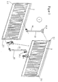
- FIG. 1 shows a radiator according to the invention, which consists of two Single plates exist in an exploded perspective view.
- the radiator 1 shown consists of two individual plates 2 and 3 with one centrally arranged manifold set 4 for connecting the radiator to a Forward and a return line 5 and 6 of a heating circuit.
- the Flow connection 5 is in the middle with a longitudinal channel of the front plate 2, and the return connection 6 in the middle with a longitudinal channel of the rear plate 3 connected.
- the pipe fittings 12 and 13 have openings 12.1 and 12 in the upper region 13.1 in which either a regulating valve or a shut-off valve Vent valve can be introduced.
- FIG. 2 shows a radiator of the same type as FIG. 1 with the following described features:
- a riser 4.1 is arranged, which has an L-shaped Connector 7 with the upper longitudinal channel 2.1 of the front Plate 2 is connected.
- the top connectors 8, 9 are T-shaped and the lower connectors 10, 11 are tubular educated.
- the upper connecting pieces 8, 9 are provided with a passage barrier 15 * provided front plate 2.
- the lower connectors 10, 11 are with a passage barrier 15 ** to the rear plate 3.
- the front plate 2 has 2.1 and the top rear plate 3 below 3.2 no connection openings.
Landscapes
- Engineering & Computer Science (AREA)
- Physics & Mathematics (AREA)
- Thermal Sciences (AREA)
- Chemical & Material Sciences (AREA)
- Combustion & Propulsion (AREA)
- Mechanical Engineering (AREA)
- General Engineering & Computer Science (AREA)
- Domestic Hot-Water Supply Systems And Details Of Heating Systems (AREA)
- Steam Or Hot-Water Central Heating Systems (AREA)
- Air-Conditioning For Vehicles (AREA)
- Cooling, Air Intake And Gas Exhaust, And Fuel Tank Arrangements In Propulsion Units (AREA)
Abstract
Description
Claims (11)
- Heizkörper, bestehend aus mindestens zwei Einzelplatten (2, 3) mit einer mittig angeordneten Verteilergarnitur (4) zum Anschluss des Heizkörpers (1) an eine Vor- und eine Rücklaufleitung (5, 6) eines Heizkreislaufes, dadurch gekennzeichnet ,dass
der Vorlaufanschluss (5) mittig mit einem Längskanal der vorderen Platte (2), und der Rücklaufanschluss (6) mittig mit einem Längskanal einer hinteren Platte (3) verbunden ist und zwischen der vorderen Platte (2) und einer dahinterliegenden Platte (3) im Bereich der Stirnseiten je eine Rohrgarnitur (12, 13) angeordnet ist, die jeweils den unteren Längskanal (2.2) der vorderen Platte (2) mit dem oberen Längskanal (3.1) der hinteren Platte (3) verbindet. - Heizkörper nach Anspruch 1, dadurch gekennzeichnet, dass die Rohrgarnituren (12, 13) Öffnungen zur Anordnung von Aufnahmen (12.1, 13.1) aufweisen, die zur wahlweisen Aufnahme von Regelund/oder Entlüftungsventilen vorgesehen sind.
- Heizkörper nach den Ansprüche 1 und 2,dadurch gekennzeichnet, dass am Vorlaufanschluss (5) eine Steigleitung (4.1) angeordnet ist, die über ein
L-förmiges Verbindungsstück (7) mit dem oberen Längskanal (2.1) der vorderen Platte (2) verbunden ist. - Heizkörper nach einem der oben genannten Ansprüche, dadurch gekennzeichnet, dass im oberen und unteren Bereich der Stirnseiten des Heizkörpers (1) Verbindungsstücke (8, 9, 10, 11) vorgesehen sind, die an jeder Seite mindestens eine Aufnahme (12.1, 13.1) zur wahlweisen Anordnung von Regel- und/oder Entlüftungsventilen aufweisen.
- Heizkörper nach einem der oben genannten Ansprüche, dadurch gekennzeichnet, dass die Verbindungsstücke (8, 9, 10, 11) mit einem Sperrorgan (15) versehen ist.
- Heizkörper nach einem der oben genannten Ansprüche, dadurch gekennzeichnet, dass die Steigleitungen (4.1, 16, 17) und die Verbindungsstücke (8, 9, 10, 11) aus Stahl bestehen.
- Heizkörper nach einem der oben genannten Ansprüche, dadurch gekennzeichnet, dass die oberen Verbindungsstücke (8, 9) T-förmig und die unteren Verbindungsstücke (10, 11) rohrförmig ausgebildet sind.
- Heizkörper nach einem der oben genannten Ansprüche, dadurch gekennzeichnet, dass die oberen Verbindungsstücke (8, 9) mit einem Gewinde versehen sind, in welchem wahlweise ein Regelventil oder ein Entlüftungsventil ein- oder aufschraubbar ist.
- Heizkörper nach einem der oben genannten Ansprüche, dadurch gekennzeichnet, dass die oberen Verbindungsstücke (8, 9) mit einer Durchgangssperre (15*) zur vorderen Platte (2) versehen sind.
- Heizkörper nach einem der oben genannten Ansprüche, dadurch gekennzeichnet, dass die unteren Verbindungsstücke (10, 11) mit einer Durchgangssperre (15**) zur hinteren Platte (3) versehen sind.
- Heizkörper nach einem der oben genannten Ansprüche, dadurch gekennzeichnet, dass die vordere Platte (2) oben (2.1) und die hintere Platte (3) unten (3.2) keine Verbindungsöffnungen aufweisen.
Applications Claiming Priority (2)
| Application Number | Priority Date | Filing Date | Title |
|---|---|---|---|
| DE10113125A DE10113125A1 (de) | 2001-03-17 | 2001-03-17 | Heizkörper mit einer mittig angeordneten Ventilgarnitur |
| DE10113125 | 2001-03-17 |
Publications (3)
| Publication Number | Publication Date |
|---|---|
| EP1241415A2 true EP1241415A2 (de) | 2002-09-18 |
| EP1241415A3 EP1241415A3 (de) | 2003-10-08 |
| EP1241415B1 EP1241415B1 (de) | 2006-10-04 |
Family
ID=7677988
Family Applications (1)
| Application Number | Title | Priority Date | Filing Date |
|---|---|---|---|
| EP02090034A Expired - Lifetime EP1241415B1 (de) | 2001-03-17 | 2002-01-24 | Heizkörper mit einer mittig angeordneten Ventilgarnitur |
Country Status (5)
| Country | Link |
|---|---|
| EP (1) | EP1241415B1 (de) |
| AT (1) | ATE341741T1 (de) |
| CZ (1) | CZ300414B6 (de) |
| DE (2) | DE10113125A1 (de) |
| PL (1) | PL204082B1 (de) |
Cited By (2)
| Publication number | Priority date | Publication date | Assignee | Title |
|---|---|---|---|---|
| EP1279904A3 (de) * | 2001-07-24 | 2004-01-14 | Hans Berg GmbH & Co. KG | Plattenheizkörper |
| GB2393779A (en) * | 2002-09-18 | 2004-04-07 | Tms Turker Makina Sanayi Ve Ti | Central heating radiator |
Citations (4)
| Publication number | Priority date | Publication date | Assignee | Title |
|---|---|---|---|---|
| DE4345037A1 (de) | 1993-12-30 | 1995-07-06 | Kermi Gmbh | Vorrichtung zum insbesondere mittigen Anschließen eines Heizkörpers, sowie Verfahren zur Herstellung bestimmter Bereiche der Vorrichtung und mittenangeschlossener Heizkörper |
| EP0737126A1 (de) | 1993-12-29 | 1996-10-16 | Shell Internationale Researchmaatschappij B.V. | Verfahren und vorrichtung zum harzimprägnieren eines porösen gewebes |
| DE19539222C1 (de) | 1995-10-23 | 1997-04-24 | Baumann Gmbh | Heizkörperanordnung |
| DE19729633A1 (de) | 1997-07-10 | 1999-01-14 | Kermi Gmbh | Ein- oder mehrreihiger Heizkörper mit zumindest zwei verschieden ausgelegten Abschnitten |
Family Cites Families (7)
| Publication number | Priority date | Publication date | Assignee | Title |
|---|---|---|---|---|
| DE19614330C1 (de) * | 1996-04-11 | 1997-03-13 | Oventrop Sohn Kg F W | Mehrlagiger Plattenheizkörper mit integrierter Ventilgarnitur |
| DE19709534A1 (de) * | 1997-03-10 | 1998-09-24 | Oventrop Sohn Kg F W | Von Fluid als Wärmeträger durchströmbarer Heizkörper |
| DE19750109C2 (de) * | 1997-11-12 | 2000-09-21 | Kermi Gmbh | Anschlußgarnitur und Heizkörper |
| DE19832051C2 (de) * | 1998-07-16 | 2002-06-13 | Kermi Gmbh | Heiz- bzw. Kühlkörper-Verteileranordnung |
| AT411294B (de) * | 1999-03-12 | 2003-11-25 | Vogel & Noot Waermetechnik Ag | Heiz-(kühl-)körper |
| DE20003375U1 (de) * | 2000-02-24 | 2000-04-13 | Hans Berg GmbH & Co KG, 51580 Reichshof | Flachheizkörper |
| DE20101345U1 (de) * | 2001-01-25 | 2001-03-29 | König, Christel, 63674 Altenstadt | Heizkörperanordnung |
-
2001
- 2001-03-17 DE DE10113125A patent/DE10113125A1/de not_active Withdrawn
-
2002
- 2002-01-24 EP EP02090034A patent/EP1241415B1/de not_active Expired - Lifetime
- 2002-01-24 AT AT02090034T patent/ATE341741T1/de active
- 2002-01-24 DE DE50208302T patent/DE50208302D1/de not_active Expired - Lifetime
- 2002-02-01 CZ CZ20020397A patent/CZ300414B6/cs not_active IP Right Cessation
- 2002-02-22 PL PL352423A patent/PL204082B1/pl unknown
Patent Citations (4)
| Publication number | Priority date | Publication date | Assignee | Title |
|---|---|---|---|---|
| EP0737126A1 (de) | 1993-12-29 | 1996-10-16 | Shell Internationale Researchmaatschappij B.V. | Verfahren und vorrichtung zum harzimprägnieren eines porösen gewebes |
| DE4345037A1 (de) | 1993-12-30 | 1995-07-06 | Kermi Gmbh | Vorrichtung zum insbesondere mittigen Anschließen eines Heizkörpers, sowie Verfahren zur Herstellung bestimmter Bereiche der Vorrichtung und mittenangeschlossener Heizkörper |
| DE19539222C1 (de) | 1995-10-23 | 1997-04-24 | Baumann Gmbh | Heizkörperanordnung |
| DE19729633A1 (de) | 1997-07-10 | 1999-01-14 | Kermi Gmbh | Ein- oder mehrreihiger Heizkörper mit zumindest zwei verschieden ausgelegten Abschnitten |
Cited By (2)
| Publication number | Priority date | Publication date | Assignee | Title |
|---|---|---|---|---|
| EP1279904A3 (de) * | 2001-07-24 | 2004-01-14 | Hans Berg GmbH & Co. KG | Plattenheizkörper |
| GB2393779A (en) * | 2002-09-18 | 2004-04-07 | Tms Turker Makina Sanayi Ve Ti | Central heating radiator |
Also Published As
| Publication number | Publication date |
|---|---|
| EP1241415A3 (de) | 2003-10-08 |
| ATE341741T1 (de) | 2006-10-15 |
| CZ2002397A3 (cs) | 2002-11-13 |
| DE50208302D1 (de) | 2006-11-16 |
| DE10113125A1 (de) | 2002-09-19 |
| CZ300414B6 (cs) | 2009-05-13 |
| EP1241415B1 (de) | 2006-10-04 |
| PL204082B1 (pl) | 2009-12-31 |
| PL352423A1 (en) | 2002-09-23 |
Similar Documents
| Publication | Publication Date | Title |
|---|---|---|
| DE60106312T2 (de) | Fluidregelvorrichtung | |
| DE112020002584T5 (de) | Verteilerrohre für eine Verteilerrohrleitung | |
| EP2023057B1 (de) | Vorschaltgarnitur für Heizkörper | |
| EP1241415B1 (de) | Heizkörper mit einer mittig angeordneten Ventilgarnitur | |
| EP0612963B1 (de) | Verteileraggregat für mit einem strömungsfähigen Wärmeträgermedium arbeitende Heiz- oder Kühlanlagen | |
| DE19750109C2 (de) | Anschlußgarnitur und Heizkörper | |
| EP0952410A2 (de) | Heizkörper | |
| DE202004019873U1 (de) | Verteilervorrichtung für einen mit einem flüssigen Medium betriebenen Kreislauf einer Wärmeversorgungsanlage | |
| AT506080B1 (de) | Installations-montagemodul | |
| DE10102022B4 (de) | Wasserheizanlage | |
| CH659719A5 (de) | Regelarmatur fuer eine flaechenklimatisiervorrichtung. | |
| DE102006020499A1 (de) | Kühlgerät | |
| DE10223790B4 (de) | Plattenheizkörper | |
| DE19744482C1 (de) | Anschlußsystem für Heizkörper | |
| EP2171365B1 (de) | Heizkörper mit teillastfunktion | |
| EP0829687A2 (de) | Befülleinrichtung für Hydraulikbaugruppe | |
| AT409545B (de) | Heiz-(kühl-)körper | |
| EP3109561B1 (de) | Heizkörper | |
| CH693966A5 (de) | Heizkoerper und Anschlussgarnitur. | |
| DE9412801U1 (de) | Heizkörperanordnung | |
| AT409660B (de) | Vorgefertigtes abzweigelement für zweirohr-heizungsanlagen | |
| DE202024101950U1 (de) | Hydraulikmodul für ein Zentralheizungssystem bzw. Zentralheizungssystem mit dem zuvor genannten Hydraulikmodul | |
| DE102006031406A1 (de) | Heizkörper, insbesondere Röhrenradiator | |
| DE20021519U1 (de) | Heizkörper mit einer mittig angeordneten Verteilergarnitur | |
| EP0794394B1 (de) | Heizkörper-Anschlussarmatur |
Legal Events
| Date | Code | Title | Description |
|---|---|---|---|
| PUAI | Public reference made under article 153(3) epc to a published international application that has entered the european phase |
Free format text: ORIGINAL CODE: 0009012 |
|
| AK | Designated contracting states |
Kind code of ref document: A2 Designated state(s): AT BE CH CY DE DK ES FI FR GB GR IE IT LI LU MC NL PT SE TR |
|
| AX | Request for extension of the european patent |
Free format text: AL;LT;LV;MK;RO;SI |
|
| PUAL | Search report despatched |
Free format text: ORIGINAL CODE: 0009013 |
|
| AK | Designated contracting states |
Kind code of ref document: A3 Designated state(s): AT BE CH CY DE DK ES FI FR GB GR IE IT LI LU MC NL PT SE TR |
|
| AX | Request for extension of the european patent |
Extension state: AL LT LV MK RO SI |
|
| 17P | Request for examination filed |
Effective date: 20031201 |
|
| AKX | Designation fees paid |
Designated state(s): AT DE |
|
| GRAP | Despatch of communication of intention to grant a patent |
Free format text: ORIGINAL CODE: EPIDOSNIGR1 |
|
| GRAS | Grant fee paid |
Free format text: ORIGINAL CODE: EPIDOSNIGR3 |
|
| GRAA | (expected) grant |
Free format text: ORIGINAL CODE: 0009210 |
|
| AK | Designated contracting states |
Kind code of ref document: B1 Designated state(s): AT DE |
|
| REF | Corresponds to: |
Ref document number: 50208302 Country of ref document: DE Date of ref document: 20061116 Kind code of ref document: P |
|
| PLBE | No opposition filed within time limit |
Free format text: ORIGINAL CODE: 0009261 |
|
| STAA | Information on the status of an ep patent application or granted ep patent |
Free format text: STATUS: NO OPPOSITION FILED WITHIN TIME LIMIT |
|
| 26N | No opposition filed |
Effective date: 20070705 |
|
| PGFP | Annual fee paid to national office [announced via postgrant information from national office to epo] |
Ref country code: DE Payment date: 20171218 Year of fee payment: 17 |
|
| PGFP | Annual fee paid to national office [announced via postgrant information from national office to epo] |
Ref country code: AT Payment date: 20180122 Year of fee payment: 17 |
|
| REG | Reference to a national code |
Ref country code: DE Ref legal event code: R082 Ref document number: 50208302 Country of ref document: DE |
|
| REG | Reference to a national code |
Ref country code: DE Ref legal event code: R119 Ref document number: 50208302 Country of ref document: DE |
|
| REG | Reference to a national code |
Ref country code: AT Ref legal event code: MM01 Ref document number: 341741 Country of ref document: AT Kind code of ref document: T Effective date: 20190124 |
|
| PG25 | Lapsed in a contracting state [announced via postgrant information from national office to epo] |
Ref country code: DE Free format text: LAPSE BECAUSE OF NON-PAYMENT OF DUE FEES Effective date: 20190801 |
|
| PG25 | Lapsed in a contracting state [announced via postgrant information from national office to epo] |
Ref country code: AT Free format text: LAPSE BECAUSE OF NON-PAYMENT OF DUE FEES Effective date: 20190124 |