EP1241452A2 - Procédé pour la détermination du niveau de remplissage d'un réservoir dans des véhicules à moteur - Google Patents
Procédé pour la détermination du niveau de remplissage d'un réservoir dans des véhicules à moteur Download PDFInfo
- Publication number
- EP1241452A2 EP1241452A2 EP02003875A EP02003875A EP1241452A2 EP 1241452 A2 EP1241452 A2 EP 1241452A2 EP 02003875 A EP02003875 A EP 02003875A EP 02003875 A EP02003875 A EP 02003875A EP 1241452 A2 EP1241452 A2 EP 1241452A2
- Authority
- EP
- European Patent Office
- Prior art keywords
- level
- value
- motor vehicle
- level value
- tank
- Prior art date
- Legal status (The legal status is an assumption and is not a legal conclusion. Google has not performed a legal analysis and makes no representation as to the accuracy of the status listed.)
- Withdrawn
Links
- 238000000034 method Methods 0.000 title claims abstract description 50
- 238000004364 calculation method Methods 0.000 claims abstract description 13
- 238000005259 measurement Methods 0.000 claims abstract description 10
- 230000001133 acceleration Effects 0.000 claims description 20
- 238000012937 correction Methods 0.000 claims description 16
- 230000010354 integration Effects 0.000 claims description 6
- 239000000446 fuel Substances 0.000 abstract description 17
- 230000001419 dependent effect Effects 0.000 abstract description 2
- 239000007788 liquid Substances 0.000 description 9
- 238000011156 evaluation Methods 0.000 description 3
- XUIMIQQOPSSXEZ-UHFFFAOYSA-N Silicon Chemical compound [Si] XUIMIQQOPSSXEZ-UHFFFAOYSA-N 0.000 description 2
- 230000015572 biosynthetic process Effects 0.000 description 2
- 238000004891 communication Methods 0.000 description 2
- 238000001514 detection method Methods 0.000 description 2
- 239000002360 explosive Substances 0.000 description 2
- 238000002347 injection Methods 0.000 description 2
- 239000007924 injection Substances 0.000 description 2
- 229910052710 silicon Inorganic materials 0.000 description 2
- 239000010703 silicon Substances 0.000 description 2
- 208000033748 Device issues Diseases 0.000 description 1
- 244000089486 Phragmites australis subsp australis Species 0.000 description 1
- 238000009825 accumulation Methods 0.000 description 1
- 239000003990 capacitor Substances 0.000 description 1
- 230000002950 deficient Effects 0.000 description 1
- 238000005516 engineering process Methods 0.000 description 1
- 238000007667 floating Methods 0.000 description 1
- 239000002828 fuel tank Substances 0.000 description 1
- 238000009499 grossing Methods 0.000 description 1
- 230000001939 inductive effect Effects 0.000 description 1
- 230000009347 mechanical transmission Effects 0.000 description 1
- 230000008092 positive effect Effects 0.000 description 1
Images


Classifications
-
- G—PHYSICS
- G01—MEASURING; TESTING
- G01F—MEASURING VOLUME, VOLUME FLOW, MASS FLOW OR LIQUID LEVEL; METERING BY VOLUME
- G01F9/00—Measuring volume flow relative to another variable, e.g. of liquid fuel for an engine
- G01F9/008—Measuring volume flow relative to another variable, e.g. of liquid fuel for an engine where the other variable is the flight or running time
-
- G—PHYSICS
- G01—MEASURING; TESTING
- G01F—MEASURING VOLUME, VOLUME FLOW, MASS FLOW OR LIQUID LEVEL; METERING BY VOLUME
- G01F23/00—Indicating or measuring liquid level or level of fluent solid material, e.g. indicating in terms of volume or indicating by means of an alarm
- G01F23/80—Arrangements for signal processing
- G01F23/802—Particular electronic circuits for digital processing equipment
- G01F23/804—Particular electronic circuits for digital processing equipment containing circuits handling parameters other than liquid level
Definitions
- level measuring devices are used to measure the level of the fuel (petrol, diesel ...) in the fuel tank.
- the current level will be communicated to the motor vehicle driver via a display, so that he has the expected range of the motor vehicle with the fuel remaining in the tank and the need to fill up the tank.
- Level measuring devices for tanks have been known for more than 20 years, in which the Buoyancy body of a rotatably mounted float in the area of the liquid level the liquid in the tank in question is floating.
- the axis of rotation of the Float which is usually below the highest possible liquid level connected to the input side of a mechanical transmission, on the output side a magnet is mounted.
- the angular position depending on the level of the liquid the float is thus transferred to the magnet, the angular position of which is a The measure of the level is.
- the magnet is located near the outside of the tank. Its rotational position is in older embodiments of the known level measuring device through a housing wall through a second rotatably mounted Detected magnet, which is mechanically coupled to a display device.
- This level measuring device is suitable for tanks in which flammable or explosive Liquids are stored. Because with the gearbox that is in the potentially explosive area is arranged is not a problematic implementation with regard to its tightness required by the tank wall.
- the magnet stored outside the tank interior replaced a magnetic field sensor, which is connected to an electronic evaluation device is. This sensor detects the magnetic field depending on the angular position of the magnet, which is a measure of the level and with the help of the evaluation device into one Level value can be converted.
- DE 199 25 185 A1 relates to a level measuring device for a tank with a an axis of rotation rotatably mounted float and with a first end and one second end tube which is set up with its second end to reach the outside of the tank and sealed against the interior of the tank is.
- a magnet is attached to the float.
- a magnetic field sensor is arranged, which is set up to one of the angular position of the float-dependent signal via an electrical line to an evaluation device issue.
- DE 40 25 184 A1 relates to a sensor for detecting the acceleration or inclination, especially for motor vehicles. It has a cylindrical liquid container, in which there is an electrically conductive liquid. Protrude into the liquid container from below two electrodes, which are coated with a dielectric. The electrodes and the conductive liquid work as a condenser. From the capacities of these capacitors the position of the sensor and thus its inclination is determined.
- acceleration sensors are known in the prior art. According to the automotive paperback, Bosch, 23rd edition, Viehweg Verlag (1999), pages 103 to 109, the following sensors are suitable, for example, for detecting corner accelerations and changes in speed: inductive sensors, Hall sensors, micromechanical silicon rotation rate sensors, Hall acceleration sensors, piezoelectric sensors or capacitive silicon acceleration sensors.
- the current fill level means that at a certain point in time portion of the tank volume filled with fuel.
- the initial level is the one Level, which is immediately after the start of the motor vehicle engine with the level measuring device measured level is determined and then as an input value is used for the subsequent process steps until there is a new input value results.
- the level measuring device may be a conventional one in the prior art act used level measuring device for a tank.
- a level measuring device is conceivable which contains a float rotatably mounted about an axis of rotation, its angular position, for example with the help of a magnet and a magnetic field sensor or is determined using a potentiometer.
- Level sensors are also used conceivable, the capacitance or resistance between arranged in the tank Measure electrodes.
- any other are for the present invention Types of level measuring device suitable.
- the consumption value of the motor vehicle lies in engines with fuel injection in the prior art.
- a window around a level value means an area around the level value, i.e. a range of values that in each case contains the level value itself, but also includes larger and / or smaller values surrounding the level value.
- the display of the new input value as the current fill level can be done by a the technology already existing in the motor vehicle level indicator. It can are, for example, an analog display that is in the driver information area of the motor vehicle, possibly as part of the instrument cluster.
- the advantages of the method according to the invention can be seen in the fact that the accuracy the level indicator is increased and that a more precise determination of the range of the Motor vehicle is possible.
- the accuracy is mainly increased by the fact that the State of the art existing influence of the dynamics of the tank content on the display, especially when sloshing and cornering is eliminated.
- Another The advantage is that inaccuracies in the residual quantity range due to the Floats of the level measuring device can occur on the tank bottom, largely be eliminated. It is also advantageous that those required to use the method Measuring devices, sensors and computers already exist in the motor vehicle are. Required extensions of the previous fuel gauge only appear in the form of Software on, hardware is also not required, which in turn has a positive effect on the Cost of the procedure affects.
- the fill level of the tank at the start of the motor vehicle engine can therefore be from a the fill level measured above can be determined. It can be assumed that the motor vehicle is at the start of the motor vehicle engine not moved and thus errors in the measured level due to the dynamics of the Tank contents can be excluded. Furthermore, the level can be determined at the start of the motor vehicle engine a correction with the level measuring device measured starting fill level, in particular measurement errors that are due to the inclination or inclination of the motor vehicle. By an inclination or An inclination of the motor vehicle is followed by an inclination or inclination of the fuel surface in the tank, which can lead to a distortion of the measured level.
- the Correction of the measured fill level can be carried out according to an embodiment of the invention with the help of vehicle location information. These can be the inclination or incline of the motor vehicle, these two sizes by at least one sensor can be detected. Sensors for the detection of motor vehicle position information are already integrated in the motor vehicle in the prior art.
- the correction of the The measured fill level is preferably carried out with the aid of the position of the motor vehicle and / or Acceleration information.
- the vehicle location information can include the inclination or incline of the motor vehicle, these two Sizes are detected by at least one sensor.
- the sensors required for Detection of the vehicle position and acceleration information are in modern Vehicles already included, for example those for vehicle dynamics systems such as ESP or for the headlamp leveling required vehicle position or acceleration sensors.
- the influence of the vehicle position and acceleration on the level measuring device can be corrected using correction algorithms.
- the correction algorithms are based among other things on the knowledge of the course of the measured by the level measuring device Level depending on the vehicle position and the acceleration.
- the information about the current consumption is for engines with fuel injection already before.
- the instantaneous consumption is integrated in order to know the absolute consumption, which is subtracted from the input value to calculate the second level value.
- the input value is either the measured (and possibly corrected) level directly after the start of the vehicle or the last time on the level indicator displayed level.
- the window is calculated from the error in the consumption calculation. This error increases due to the accumulation of small sizes (integration) over time. This window then defines the area in which the fill level of the Motor vehicle tanks located real. It is limited by the maximum and the minimum possible level, which results from the largest possible error.
- the first level value is the new input value, if the first Level value in the window is around the second level value and that the second level value the new input value is if the first level value is outside the window around the second level value.
- the window is the next The procedure is very small because the level value is assumed to be exact and the calculation of the absolute consumption is based on this new "exact" input value.
- the window becomes larger the next time the process is run the integration of the current consumption is continued and the error thereby increased. The resulting error that increases over time from the consumption calculation is due to the combination with the corrected measured value of the level measuring device kept as low as possible.
- the measured values of the level measuring device, the inclination and inclination sensors, the acceleration sensors and the Combined sensors for the determination of instantaneous consumption is that the extension of a modern motor vehicle to carry out the method according to the invention only in Form of software is required. Hardware is also not required because the required Components in the prior art are already present in the motor vehicle.
- the Required calculations and correction algorithms can already be done in the vehicle located computers, for example the engine control unit or the control unit of the Combi instruments are carried out.
- the level of the motor vehicle tank is indicated to the driver of the motor vehicle via suitable ones Display instruments that are connected to the computers mentioned above.
- the display is digital Display. This was previously not possible in the prior art because the level displayed fluctuated too much, making a digital display bad would have been readable. In the more accurate determined according to the present invention Level, the fluctuations are greatly reduced and therefore is a digital display possible.
- the range of a motor vehicle is to be understood as the way that can be driven with the fuel remaining in the motor vehicle tank.
- the correction of the level measurement errors resulting from the vehicle position can alternatively to the methods described above by skillfully installing one or more fuel level sensors as a level measuring device.
- a centrally arranged tank level sensor serves as a level measuring device. It is advantageous that there is an inclination of the fuel surface has the least impact on the measured level at the central point.
- a Another embodiment of the invention serve in a saddle tank at least two in Tank level sensor arranged in both chambers as a level measuring device.
- the invention further relates to the use of the method according to the invention for Checking the function of the level measuring device, with each pass of the Procedure after comparing the first level with the window around the second Level value is checked how often the first level value within the window lies. If the first level value is often in the window, the calculated level is correct and the level measured by the level measuring device often coincides with the level measuring device works. If the values rarely match, it can be assumed that the level measuring device is defective.
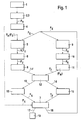
- Figure 1 shows a flow chart of a method according to the invention.
- the start fill level 2 in the motor vehicle tank is measured by a fill level measuring device 3.
- the measured start fill level F S is corrected 4 on the basis of motor vehicle position information, from which the initial fill level F A results, which is the input value F E serves.
- the input value F E can be passed on to the fill level indicator 7 so that it displays the input value F E as the current fill level.
- the calculation 6 of the second fill level value F 2 can be carried out from the input value F E and by integrating the instantaneous consumption 5.
- a window ⁇ F around the second fill level value F 2 is formed from the error ⁇ F of the consumption V, which results from the integration of the instantaneous consumption 8.
- the first fill level value F 1 is determined, by measuring the fill level 9 with a fill level measuring device, correcting 10 the measured fill level F G on the basis of vehicle position and acceleration information (F K ) and by forming the moving average 11 (F M ).
- the calculated moving average F M is the first level value F 1 .
- it is checked whether the first fill level value F 1 lies in the window ⁇ F. In the first case 13, the first fill level value F 1 is not in the window ⁇ F and the second fill level value F 2 serves as the new input value F E (F E F 2 ) 15.
- the level indicator 7 shows the new input value F E as the current level.
- Figure 2 shows the basic arrangement for implementing the method according to the invention based on a multi-sensor concept.
- a fill level measuring device 3 sensors for determining the instantaneous consumption 20, inclination and inclination sensors 21 and acceleration sensors 22 are connected to an information path 23 present in the motor vehicle, for example a CAN bus.
- the measured values of the sensors that is to say measured fill level F G , instantaneous consumption V m , inclination and inclination information I N, S and / or acceleration information I B are passed on to computer 24 via information path 23.
- the computer 24 can be, for example, a control unit of the instrument cluster or the engine control.
- the computer 24 carries out the necessary calculations and correction algorithms. This includes the correction of the level F G measured with the level measuring device 3 on the basis of the inclination / inclination and / or acceleration information (I N, S , I B ).
- the computer 24 It is also the task of the computer 24 to form the moving average value F M. Furthermore, the computer 24 is used to integrate the instantaneous consumption V m and to calculate the second fill level F 2 and the window ⁇ F. After the case distinction 12 has taken place, a new input value F E and possibly the calculated range R are passed on from the computer 24 via the information path 23 to the level indicator (or the range indicator) 25.
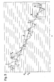
- FIG. 3 shows an example of the fill level curve determined by the method according to the invention.
- the course of the corrected level F K measured with the level measuring device and the input value F E indicated by the level indicator are shown as a function of time t.
- the corrected measured level F K shows significant fluctuations in the order of magnitude of several liters. These fluctuations are a consequence of the dynamics of the tank content.
- the input value F E resulting from the method according to the invention which is communicated to the motor vehicle driver via the fill level indicator, is significantly smoother. Many intersections of the input value F E with the corrected measured fill level F K can be seen.
- the input value F E indicated by the level indicator achieves an accuracy of +/- 11.
- the influence of the dynamics of the tank content on the corrected measured level F K in particular in sloshing and cornering is eliminated by the method according to the invention, in particular by taking into account the current consumption.
- FIG. 4 shows the enlarged section A from FIG. 3.
- the window ⁇ F widens clearly around F 2 , since the errors increase due to the integration of the instantaneous consumption.
- the second level value F 2 is accepted as the input value F E , the errors increase.
- the first fill level value F 1 adopted as the input value F E and the error in consumption is set to zero. This can be clearly seen at point X.
- the width of the window ⁇ F is again set to zero at this point X.
Landscapes
- Engineering & Computer Science (AREA)
- Signal Processing (AREA)
- Physics & Mathematics (AREA)
- Fluid Mechanics (AREA)
- General Physics & Mathematics (AREA)
- Measurement Of Levels Of Liquids Or Fluent Solid Materials (AREA)
- Level Indicators Using A Float (AREA)
- Supplying Secondary Fuel Or The Like To Fuel, Air Or Fuel-Air Mixtures (AREA)
- Cooling, Air Intake And Gas Exhaust, And Fuel Tank Arrangements In Propulsion Units (AREA)
Applications Claiming Priority (2)
| Application Number | Priority Date | Filing Date | Title |
|---|---|---|---|
| DE10111923A DE10111923A1 (de) | 2001-03-13 | 2001-03-13 | Verfahren für eine Tank-Füllstandbestimmung bei Kraftfahrzeugen |
| DE10111923 | 2001-03-13 |
Publications (2)
| Publication Number | Publication Date |
|---|---|
| EP1241452A2 true EP1241452A2 (fr) | 2002-09-18 |
| EP1241452A3 EP1241452A3 (fr) | 2007-03-14 |
Family
ID=7677212
Family Applications (1)
| Application Number | Title | Priority Date | Filing Date |
|---|---|---|---|
| EP02003875A Withdrawn EP1241452A3 (fr) | 2001-03-13 | 2002-02-21 | Procédé pour la détermination du niveau de remplissage d'un réservoir dans des véhicules à moteur |
Country Status (3)
| Country | Link |
|---|---|
| US (1) | US6666084B2 (fr) |
| EP (1) | EP1241452A3 (fr) |
| DE (1) | DE10111923A1 (fr) |
Cited By (4)
| Publication number | Priority date | Publication date | Assignee | Title |
|---|---|---|---|---|
| DE102004024513A1 (de) * | 2004-05-18 | 2005-12-15 | Adam Opel Ag | Kraftstofftank mit einer Füllstandsmessvorrichtung |
| EP1489393A3 (fr) * | 2003-06-03 | 2007-05-30 | Endress + Hauser GmbH + Co. KG | Installation et procédé de mesure du niveau |
| WO2009004020A1 (fr) * | 2007-07-04 | 2009-01-08 | Robert Bosch Gmbh | Procédé et dispositif de détection d'un niveau de remplissage de réservoir |
| CN115953728A (zh) * | 2022-09-28 | 2023-04-11 | 三一汽车制造有限公司 | 目标行为的识别方法、装置、系统、存储介质和车辆 |
Families Citing this family (27)
| Publication number | Priority date | Publication date | Assignee | Title |
|---|---|---|---|---|
| JP2004203156A (ja) * | 2002-12-25 | 2004-07-22 | Fuji Heavy Ind Ltd | 燃料残量表示装置 |
| JP2005283127A (ja) * | 2004-03-26 | 2005-10-13 | Nissan Motor Co Ltd | 燃料量演算装置 |
| WO2006084069A2 (fr) * | 2005-02-04 | 2006-08-10 | Davco Technology, L.L.C. | Appareil et procede permettant de determiner un niveau de fluide dans un contenant ferme |
| US8161814B2 (en) * | 2008-06-09 | 2012-04-24 | Luna Labs, Inc. | Self-calibrating capacitive transducer for determining level of fluent materials |
| JP5332989B2 (ja) * | 2009-07-10 | 2013-11-06 | ソニー株式会社 | 液体タンクおよび燃料電池 |
| DE102010026771A1 (de) * | 2010-07-10 | 2012-01-12 | Gm Global Technology Operations Llc (N.D.Ges.D. Staates Delaware) | Vorrichtung und Verfahren zum Ermitteln des aktuell für ein Fahrzeug verfügbaren Kraftstoffvorrats |
| EP2466278B1 (fr) * | 2010-12-16 | 2015-01-28 | Fiat Powertrain Technologies S.p.A. | Méthode d'estimation du niveau de carburant dans le réservoir d'un véhicule et système d'estimation du niveau de carburant correspondant |
| US9170148B2 (en) * | 2011-04-18 | 2015-10-27 | Bradley Fixtures Corporation | Soap dispenser having fluid level sensor |
| EP2737233B1 (fr) * | 2011-07-29 | 2016-11-23 | Allison Transmission Inc. | Système et procédé de mesure de niveau d'huile |
| US9217690B2 (en) * | 2012-01-25 | 2015-12-22 | GM Global Technology Operations LLC | Coolant loss detection and remediation in a liquid cooled battery pack |
| US8813545B2 (en) * | 2013-01-04 | 2014-08-26 | Delphi Technologies, Inc. | Method for diagnosing component failure in a saddle-type fuel tank assembly |
| US9454856B2 (en) * | 2014-01-21 | 2016-09-27 | GM Global Technology Operations LLC | Liquefied petroleum gas tank leak detection systems and methods |
| DE102014009634A1 (de) * | 2014-06-27 | 2015-12-31 | Audi Ag | Kraftstofftank mit einem Aktivkohlefilter und Verfahren zum Anzeigen des Kraftstofffüllstands im Kraftstofftank mit Signalunterdrückung bei einem kritischen Unterdruck während der Regeneration des Aktivkohlefilters |
| JP6150839B2 (ja) * | 2015-04-14 | 2017-06-21 | 本田技研工業株式会社 | 燃料充填システム及びその燃料充填方法 |
| CN106556454A (zh) * | 2015-09-24 | 2017-04-05 | 大陆汽车电子(芜湖)有限公司 | 汽车仪表用的油量显示方法 |
| US10408666B2 (en) * | 2015-10-13 | 2019-09-10 | Medallion Instrumentation Systems, Llc | Fluid level sensor |
| JP6278032B2 (ja) | 2015-11-16 | 2018-02-14 | トヨタ自動車株式会社 | 燃料残量表示装置 |
| DE102016206129A1 (de) | 2016-04-13 | 2017-10-19 | Bayerische Motoren Werke Aktiengesellschaft | Verfahren zur Bestimmung einer Restreichweite eines Kraftfahrzeugs |
| DE102017200291A1 (de) * | 2017-01-10 | 2018-07-12 | Robert Bosch Gmbh | Wassereinspritzvorrichtung, insbesondere einer Brennkraftmaschine, und Verfahren zum Betreiben einer solchen Wassereinspritzvorrichtung |
| CN110017884B (zh) * | 2018-01-08 | 2021-09-07 | 宝沃汽车(中国)有限公司 | 车辆故障检测方法、系统、车辆云平台及车辆 |
| FR3083608B1 (fr) | 2018-07-06 | 2021-07-16 | Ifp Energies Now | Procede d'estimation d'une quantite de carburant reellement ajoutee lors d'un plein dans un reservoir de vehicule |
| US11493378B2 (en) * | 2020-09-22 | 2022-11-08 | Caterpillar Inc. | Fuel level measurement system for a machine |
| US11566575B2 (en) * | 2021-03-19 | 2023-01-31 | Intangles Lab Pvt. Ltd. | Sub-resolution measurement of fuel in fuel tank |
| US12103463B2 (en) | 2021-06-29 | 2024-10-01 | International Truck Intellectual Property Company, Llc | Air tank assembly |
| DE102022102822A1 (de) | 2022-02-07 | 2023-08-10 | Vega Grieshaber Kg | Sensor zur Bestimmung und Validierung eines Füllstands |
| LU504887B1 (en) * | 2023-08-09 | 2025-02-10 | Plastic Omnium Advanced Innovation And Res Sa | Method for determining an amount of a fluid in a container of a vehicle |
| CN121230842B (zh) * | 2025-12-03 | 2026-04-07 | 国能黄骅港务有限责任公司 | 液位测量方法、装置、电子设备和存储介质 |
Family Cites Families (8)
| Publication number | Priority date | Publication date | Assignee | Title |
|---|---|---|---|---|
| DE3021374A1 (de) * | 1980-06-06 | 1981-12-17 | Bayerische Motoren Werke AG, 8000 München | Verfahren zur bestimmung der vorratsmenge von betriebsfluueuesikeiten von kraftfahrzeugen und geber zur durchfuehrung des verfahrens |
| US4470296A (en) * | 1981-12-28 | 1984-09-11 | Nissan Motor Company, Limited | Fuel gauge for an automotive vehicle |
| FR2530807B1 (fr) * | 1982-07-26 | 1987-01-30 | Jaeger | Procede et dispositif pour la mesure de la quantite de fluide contenue dans un reservoir |
| DE3725752A1 (de) * | 1987-08-04 | 1989-03-02 | Vdo Schindling | Verfahren und vorrichtung zur anzeige des fluessigkeitsniveaus in einem kraftfahrzeugtank |
| DE4025184A1 (de) * | 1990-08-09 | 1992-02-20 | Vdo Schindling | Sensor zur erfassung der beschleunigung bzw. neigung |
| US6516661B1 (en) * | 1999-01-28 | 2003-02-11 | Simmonds Precision Products, Inc. | Volume measurement system and method for volume element counting |
| DE19925185C2 (de) * | 1999-05-26 | 2002-11-28 | Fafnir Gmbh | Füllstand-Meßvorrichtung |
| FR2794526B1 (fr) * | 1999-06-03 | 2001-10-12 | Peugeot Citroen Automobiles Sa | Systeme d'estimation de la quantite de carburant restant dans le reservoir d'un vehicule automobile |
-
2001
- 2001-03-13 DE DE10111923A patent/DE10111923A1/de not_active Ceased
-
2002
- 2002-02-21 EP EP02003875A patent/EP1241452A3/fr not_active Withdrawn
- 2002-03-13 US US10/096,634 patent/US6666084B2/en not_active Expired - Fee Related
Non-Patent Citations (1)
| Title |
|---|
| None |
Cited By (5)
| Publication number | Priority date | Publication date | Assignee | Title |
|---|---|---|---|---|
| EP1489393A3 (fr) * | 2003-06-03 | 2007-05-30 | Endress + Hauser GmbH + Co. KG | Installation et procédé de mesure du niveau |
| DE102004024513A1 (de) * | 2004-05-18 | 2005-12-15 | Adam Opel Ag | Kraftstofftank mit einer Füllstandsmessvorrichtung |
| WO2009004020A1 (fr) * | 2007-07-04 | 2009-01-08 | Robert Bosch Gmbh | Procédé et dispositif de détection d'un niveau de remplissage de réservoir |
| US8733167B2 (en) | 2007-07-04 | 2014-05-27 | Robert Bosch Gmbh | Method and device for detecting a tank level |
| CN115953728A (zh) * | 2022-09-28 | 2023-04-11 | 三一汽车制造有限公司 | 目标行为的识别方法、装置、系统、存储介质和车辆 |
Also Published As
| Publication number | Publication date |
|---|---|
| EP1241452A3 (fr) | 2007-03-14 |
| US20020194910A1 (en) | 2002-12-26 |
| US6666084B2 (en) | 2003-12-23 |
| DE10111923A1 (de) | 2002-10-02 |
Similar Documents
| Publication | Publication Date | Title |
|---|---|---|
| EP1241452A2 (fr) | Procédé pour la détermination du niveau de remplissage d'un réservoir dans des véhicules à moteur | |
| DE3342553C2 (fr) | ||
| DE19962997B4 (de) | Verfahren zur Kalibrierung eines Sensorsystems | |
| DE19540674C2 (de) | Adaptionsverfahren zur Korrektur von Toleranzen eines Geberrades | |
| DE3725752C2 (fr) | ||
| WO2000063657A1 (fr) | Procede de mesure du niveau de remplissage et detecteur du niveau de remplissage | |
| WO1985001256A1 (fr) | Procede et circuit de determination du rapport optimal quant a la consommation d'un vehicule a moteur | |
| DE19816455A1 (de) | Füllstandssensor | |
| DE2849066A1 (de) | Einrichtung zur anzeige des fuellstandes in einem fahrzeugtank | |
| WO1992008953A1 (fr) | Procede pour la determination de la position d'un vehicule routier | |
| DE102018130217A1 (de) | Offset-Erkennung für einen Kraftstofffüllstandsensorfehler | |
| DE19929426A1 (de) | Verfahren zur Bestimmung einer zurücklegbaren Restentfernung und Anordnung dazu | |
| DE4215938C2 (de) | Aussetzererkennungssystem bei einem Verbrennungsmotor | |
| DE102004026639A1 (de) | Verfahren zur Bestimmung einer Höhen- oder Steigungsinformation in einem Kraftfahrzeug | |
| EP1364189B1 (fr) | Procede permettant de determiner le niveau d'un produit de fonctionnement dans un vehicule a moteur | |
| WO2021078507A1 (fr) | Système de détection pour véhicules, en particulier pour véhicules à moteur, destiné à détecter la vitesse d'un véhicule, l'assiette du véhicule et/ou l'état de la suspension du véhicule, agencement pour un tel système de détection et véhicule équipé d'un tel système de détection | |
| DE3526515C2 (fr) | ||
| DE19844911B4 (de) | Verfahren und Vorrichtung zur Überwachung eines in einem Fahrzeug eingesetzten Beschleunigungssensors | |
| EP1055058B1 (fr) | Procede pour la determination d'une grandeur de fonctionnement d'un vehicule automobile | |
| DE102014220522B4 (de) | Bestimmung eines korrigierten Drucksignals | |
| WO2006089686A2 (fr) | Dispositif de commande de vehicule a moteur | |
| DE3049158C2 (fr) | ||
| DE3537088C1 (de) | Vorrichtung zur Anzeige und Messung des Fuellstandes eines Kraftstofftankes in einem Fahrzeug | |
| DE4309605C2 (de) | Verfahren zur Anzeige eines Betriebsflüssigkeitsvorrats von Kraftfahrzeugen | |
| DE102007001674A1 (de) | Verfahren zur Ermittlung eines Antriebsmoments eines Kraftfahrzeugs |
Legal Events
| Date | Code | Title | Description |
|---|---|---|---|
| PUAI | Public reference made under article 153(3) epc to a published international application that has entered the european phase |
Free format text: ORIGINAL CODE: 0009012 |
|
| AK | Designated contracting states |
Kind code of ref document: A2 Designated state(s): AT BE CH CY DE DK ES FI FR GB GR IE IT LI LU MC NL PT SE TR |
|
| AX | Request for extension of the european patent |
Free format text: AL;LT;LV;MK;RO;SI |
|
| PUAL | Search report despatched |
Free format text: ORIGINAL CODE: 0009013 |
|
| AK | Designated contracting states |
Kind code of ref document: A3 Designated state(s): AT BE CH CY DE DK ES FI FR GB GR IE IT LI LU MC NL PT SE TR |
|
| AX | Request for extension of the european patent |
Extension state: AL LT LV MK RO SI |
|
| 17P | Request for examination filed |
Effective date: 20070914 |
|
| AKX | Designation fees paid |
Designated state(s): DE FR GB IT SE |
|
| 17Q | First examination report despatched |
Effective date: 20091023 |
|
| STAA | Information on the status of an ep patent application or granted ep patent |
Free format text: STATUS: THE APPLICATION IS DEEMED TO BE WITHDRAWN |
|
| 18D | Application deemed to be withdrawn |
Effective date: 20150901 |