EP1241836A1 - Verzweigtes optisches kommunikationssystem - Google Patents
Verzweigtes optisches kommunikationssystem Download PDFInfo
- Publication number
- EP1241836A1 EP1241836A1 EP01961219A EP01961219A EP1241836A1 EP 1241836 A1 EP1241836 A1 EP 1241836A1 EP 01961219 A EP01961219 A EP 01961219A EP 01961219 A EP01961219 A EP 01961219A EP 1241836 A1 EP1241836 A1 EP 1241836A1
- Authority
- EP
- European Patent Office
- Prior art keywords
- station equipment
- equipment unit
- secondary station
- unit
- primary station
- Prior art date
- Legal status (The legal status is an assumption and is not a legal conclusion. Google has not performed a legal analysis and makes no representation as to the accuracy of the status listed.)
- Ceased
Links
Images









Classifications
-
- H—ELECTRICITY
- H04—ELECTRIC COMMUNICATION TECHNIQUE
- H04Q—SELECTING
- H04Q11/00—Selecting arrangements for multiplex systems
- H04Q11/0001—Selecting arrangements for multiplex systems using optical switching
- H04Q11/0062—Network aspects
- H04Q11/0067—Provisions for optical access or distribution networks, e.g. Gigabit Ethernet Passive Optical Network (GE-PON), ATM-based Passive Optical Network (A-PON), PON-Ring
-
- H—ELECTRICITY
- H04—ELECTRIC COMMUNICATION TECHNIQUE
- H04Q—SELECTING
- H04Q11/00—Selecting arrangements for multiplex systems
- H04Q11/0001—Selecting arrangements for multiplex systems using optical switching
- H04Q11/0062—Network aspects
-
- H—ELECTRICITY
- H04—ELECTRIC COMMUNICATION TECHNIQUE
- H04Q—SELECTING
- H04Q11/00—Selecting arrangements for multiplex systems
- H04Q11/0001—Selecting arrangements for multiplex systems using optical switching
- H04Q11/0005—Switch and router aspects
- H04Q2011/0037—Operation
- H04Q2011/0039—Electrical control
-
- H—ELECTRICITY
- H04—ELECTRIC COMMUNICATION TECHNIQUE
- H04Q—SELECTING
- H04Q11/00—Selecting arrangements for multiplex systems
- H04Q11/0001—Selecting arrangements for multiplex systems using optical switching
- H04Q11/0062—Network aspects
- H04Q2011/0064—Arbitration, scheduling or medium access control aspects
-
- H—ELECTRICITY
- H04—ELECTRIC COMMUNICATION TECHNIQUE
- H04Q—SELECTING
- H04Q11/00—Selecting arrangements for multiplex systems
- H04Q11/0001—Selecting arrangements for multiplex systems using optical switching
- H04Q11/0062—Network aspects
- H04Q2011/0079—Operation or maintenance aspects
- H04Q2011/0081—Fault tolerance; Redundancy; Recovery; Reconfigurability
Definitions
- the present invention generally relates to a passive optical network controlling redundant switching in a redundant passive optical network section.
- Fig. 1 shows a configuration of a related-art passive optical network communications system defined in International Telecommunication Union-Telecommunication (ITU-T) Recommendation G.983.1.
- the system comprises a primary station equipment unit 1, secondary station equipment units 2-1-2-n, an optical distribution network (ODN) 3 implemented by passive elements such as optical couplers and optical fibers, a primary station line termination 4 for an active system, a primary station line termination 5 for a standby system, a secondary station line termination 6 for an active system and a secondary station line termination 7 for a standby system.
- ODN optical distribution network
- ITU-T Recommendation G.983.1 a downstream signal is broadcast from the primary station equipment unit 1 to the secondary station equipment units 2-1-2-n over the ODN 3.
- Upstream signals from the secondary station equipment units 2-1-2-n are multiplexed by the ODN 3 before being sent to the primary station equipment unit 1.
- the ODN 3 effects access control (delay control) for multiplexing the upstream signals from the secondary station equipment units 2-1-2-n.
- the delay control is also described in ITU-T G. 983.1.
- Japanese Laid-Open Patent Application No. 11-122172 which is provides a duplex configuration of optical transmission system at a reduced cost by providing each of primary station equipment units and secondary station equipment units with a plurality of transceivers operated at mutually different wavelengths and with a system switcher, discloses a redundant switching system for an optical subscriber system.
- a redundant switching system for an optical subscriber system Given in the following, however, is a description of a related-art redundant switching control in a passive optical network (PON) section that conforms to ITU-T Recommendation G.983.1.
- PON passive optical network
- Fig. 2 shows a detailed configuration of the related-art passive optical network communications system.
- a secondary station equipment unit 2 is one of the secondary station equipment units 2-1-2-n.
- a 2-1 selector 11 selectively outputs one of a signal received by the primary station line termination 4 for the active system and the primary station line termination 5 for the standby system, under the direction of a selective control unit 13.
- a route setting unit 12 outputs a main signal to at least one of the primary station line termination 4 for the active system and the primary station line termination 5 for the standby system, under the direction of the selective control unit 13.
- the selective control unit 13 controls the 2-1 selector 11 and the route setting unit 12, based on K1/K2 bytes included in a PON section trace (PST) message, which is a type of physical layer operations administration and maintenance (PLOAM) message.
- PST PON section trace
- PLOAM physical layer operations administration and maintenance
- PLOAM cell composing units 14 and 15 output the PST message output from the selective control unit 13 to transceivers 18 and 19.
- Grant generating units 16 and 17 generate PLOAM grants (PLOAM cell transmission enable signals) so as to output the PLOAM grants thus generated to the transceivers 18 and 19.
- the transceivers 18 and 19 transmit the main signal, the PLOAM cell and the grant to the secondary station equipment unit 2 and also receives the main signal and the PLOAM cell from the secondary station equipment unit 2.
- PLOAM cell decomposing units 20 and 21 receive the PLOAM cell received by the transceivers 18 and 19 and output the PST message to the selective control unit 13.
- a 2-1 selector 31 selects one of a main signal received by a secondary station line termination 6 for an active system and a main signal received by a secondary station line termination 7 for a standby system, under the direction of a selective control unit 33, so as to output the selected signal.
- a route setting unit 32 outputs the main signal to at least one of the secondary station line termination 6 for the active system and the secondary station line termination 7 for the standby system, under the direction of the selective control unit 33.
- the selective control unit 33 controls the 2-1 selector 31 and the route setting unit 32, based on the K1/K2 bytes included in the PST message.
- PLOAM cell composing units 34 and 35 output the PLOAM cell including the PST message, supplied from the selective control unit 33, to the transceivers 38 and 39, the timing of output being indicated by the PLOAM grant detected by grant detecting units 36 and 37.
- the grant detecting units 36 and 37 detect PLOAM grants received by the transceivers 38 and 39.
- the transceivers 38 and 39 transmit the main signal and the PLOAM cell to the primary station equipment unit 1 and also receives the main signal, the PLOAM cell and the grant from the primary station equipment unit 1.
- PLOAM cell decomposing units 40 and 41 receive the main signal received by the transceivers 38 and 39 so as to output the PST message to the selective control unit 33.
- Fig. 3 shows an example of control effected when a failure occurs in the secondary station equipment unit 2-1.
- the operations of the primary station equipment unit 1 and the secondary station equipment units 2-1-2-n performed in the event of a failure are illustrated along a time line extending in a downward direction in the drawing.
- the 2-1 selector 11 and the route setting unit 12 select the main signal from the secondary station line termination 6 for the active system and that the 2-1 selector 31 and the route setting unit 32 select the main signal from the primary station line termination 4 for the active system.
- the main signal is transmitted and received over the active system.
- the selective control unit 33 of the secondary station equipment unit 2-1 outputs a PST message, comprising the K1 byte indicating that "switching is not requested" and the K2 byte indicating that "the active system is being selected", to the PLOAM cell composing units 34 and 35.
- the PLOAM cell including the PST message is transmitted to the primary station equipment unit 1 by the transceivers 38 and 39 of the secondary station equipment unit 2-1.
- the PLOAM cell thus transmitted is received by the transceivers 18 and 19 of the primary station equipment unit 1 so that the PLOAM cell decomposing units 20 and 21 output the PST message included in the PLOAM cell to the selective control unit 13.
- the selective control unit 13 of the primary station equipment unit 1 controls the 2-1 selector 11 and the route setting unit 12, based on the PST message thus received.
- the primary station equipment unit 1 also transmits the PST message, comprising the K1 byte and the K2 byte, to the secondary station equipment unit 2-1.
- the primary station equipment unit 1 does not undergo any failure so that the K1 byte indicating that "switching is not requested" continues to be transmitted to the secondary station equipment unit 2-1.
- the selective control unit 33 of the secondary station equipment unit 2-1 updates the PST message so as to include the K1 byte indicating that "switching is being requested due to signal fail (SF)" and the K2 byte indicating that "the active system is being selected”.
- the selective control unit 33 outputs the PST message thus updated to the PLOAM cell composing units 34 and 35 (T2).
- the PLOAM cell including the PST message is transmitted to the primary station equipment unit 1 by the transceivers 38 and 39 of the secondary station equipment unit 2-1.
- the transceiver 19 of the primary station equipment unit 1 receives the PLOAM cell (the PLOAM cell does not arrive at the transceiver 18 since the failure occurred in the active system).
- the PLOAM cell decomposing unit 21 outputs the PST message included in the PLOAM cell to the selective control unit 13 (T3).
- the selective control unit 13 of the primary station equipment unit 1 controls the route setting unit 12, based on the PST message.
- the selective control unit 13 Since the R1 byte received from the secondary station equipment unit 2-1 indicates that "switching is being requested due to signal fail (SF)", the selective control unit 13 outputs an instruction directing the route setting unit 12 to be switched to the standby system (T4).
- the primary station equipment unit 1 updates the K1 byte so as to indicate "acknowledgement” (T5) since it acknowledges at this stage that a failure occurred in the secondary station equipment unit 2-1.
- the selective control unit 13 of the primary station equipment unit 1 outputs the PST message, comprising the K1 byte indicating "acknowledgement" and the K2 byte indicating that "the active system is being selected", to the PLOAM cell composing units 14 and 15.
- the PLOAM cell including the PST message is transmitted by the transceivers 18 and 19 of the primary station equipment unit 1 to the secondary station equipment unit 2-1.
- the transceiver 39 of the secondary station equipment unit 2-1 receives the PLOAM cell.
- the PLOAM cell decomposing unit 41 outputs the PST message included in the PLOAM cell to the selective control unit 33 (T6).
- the selective control unit 33 of the secondary station equipment unit 2-1 controls the 2-1 selector 31 and the route setting unit 32, based on the PST message.
- the selective control unit 13 Since the K1 byte received indicates "acknowledgement", the selective control unit 13 outputs an instruction directing the 2-1 selector 31 and the route setting unit 32 to be switched to the standby system (T7).
- the selective control unit 33 of the secondary station equipment unit 2-1 updates the PST message so as to include the K1 byte indicating that "switching is being requested due to signal fail (SF)" and the K2 byte indicating that "the standby system is being selected” and outputs the PST message thus updated to the PLOAM cell composing units 34 and 35 (T8).
- the primary station equipment unit 1 transmits PLOAM grants (PLOAM cell transmission enable signals) to the secondary station equipment units 2-1-2-n at predetermined intervals so as to receive PLOAM cells from the secondary station equipment 2-1-2-n (T0a, T0b, T0n).
- PLOAM grants PLOAM cell transmission enable signals
- ITU-T Recommendation G. 983.1 recommends that the primary station equipment unit 1 and the secondary station equipment unit 2 transmit the PST message at predetermined intervals (for example, one message per second).
- the selective control unit 33 of the secondary station equipment unit 2-1 outputs the PST message, comprising the K1 byte indicating that "switching is being requested due to signal fail (SF)" and the K2 byte indicating that "the standby system is being selected", to the PLOAM cell composing units 34 and 35.
- the transmission of the PST message to the primary station equipment unit 1 is deferred until T71 when the PLOAM grant is received (T11).
- the PLOAM cell including the above PST message is received by the transceiver 19 of the primary station equipment unit 1, where the PLOAM cell decomposing unit 21 outputs the PST message included in the PLOAM cell to the selective control unit 13.
- the selective control unit 13 of the primary station equipment unit 1 receiving the PST message from the PLOAM cell decomposing unit 21 controls the 2-1 selector 11, based on the PST message.
- the selective control unit 13 Since the K2 byte received from the secondary station equipment unit 2-1 indicates that "the standby system is being selected", the selective control unit 13 outputs an instruction directing the 2-1 selector 11 to be switched to the standby system (T12). Subsequently, the main signal is transmitted and received over the standby system.
- the selective control unit 13 of the primary station equipment unit 1 updates the PST message so as to include the K1 byte indicating "acknowledgement" and the K2 byte indicating that "the standby system is being selected”.
- the selective control unit 13 outputs the PST message to the PLOAM cell composing units 14 and 15 (T13).
- the PLOAM cell including the PST message is transmitted to the secondary station equipment unit 2-1 by the transceivers 18 and 19 of the primary station equipment unit (T14).
- the transceiver 39 of the secondary station equipment unit 2-1 receives the PLOAM cell.
- the PLOAM cell decomposing unit 41 outputs the PST message included in the PLOAM cell to the selective control unit 33, thus completing a redundancy switching sequence.
- the PLOAM grant from the primary station equipment unit 1 is used for transmission of the PLOAM cell that is waiting.
- the above PST message naturally has to wait until a next PLOAM grant is received (not shown).
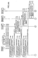
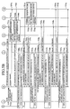
- Figs. 4a and 4B show how a failure occurring in the ODN 3 coupled to the primary station equipment unit 1 is deal with. Referring to Figs. 4A and 4B, the operations of the primary station equipment unit 1 and the secondary station equipment units 2-1-2-n occurring in the event of a failure are illustrated along a time line extending in a downward direction in the drawing.
- a failure hereinafter, referred to as a trunk failure
- the 2-1 selector 11 and the route setting unit 12 select the main signal from the secondary station line termination 6 for the active system and the 2-1 selector 31 and the route setting unit 32 select the main signal from the primary station line termination 4 for the active system.
- the main signal is transmitted and received over the active system.
- the primary station line termination 4 for the active system in the primary station equipment unit 1 detects a failure (for example, LOSi: loss of signal). corresponding to the secondary station equipment unit 2-1 (T22a).
- the selective control unit 13 of the primary station equipment unit 1 detecting the failure in the active system outputs an instruction directing the route setting unit 12 to be switched to the standby system (T26a).
- the selective control unit 13 of the primary station equipment unit 1 updates the PST message so as to include the K1 byte indicating that "switching is being requested due to signal fail (SF)" and the K2 byte indicating that "the active system is being selected” (T27a).
- the selective control unit 13 of the primary station equipment unit 1 outputs the PST message, comprising the K1 byte indicating that "switching is being requested due to signal fail (SF)" and the K2 byte indicating that "the active system is being selected", to the PLOAM cell composing units 14 and 15.
- the PLOAM cell including the PST message is transmitted to the secondary station equipment unit 2-1 by the transceivers 18 and 19 of the primary station equipment unit 1.
- the transceiver 39 of the secondary station equipment unit 2-1 receives the PLOAM cell (the PLOAM cell does not arrive at the transceiver 38 since the failure occurred in the active system).
- the PLOAM cell decomposing unit 41 outputs the PST message included in the PLOAM cell to the selective control unit 33 (T28a).
- the selective control unit 33 of the secondary station equipment unit 2-1 receiving the PST message from the PLOAM cell decomposing unit 41 controls the 2-1 selector 31 and the route setting unit 32, based on the PST message.
- the selective control unit 33 Since the K1 byte received indicates that "switching is being requested due to signal fail (SF)", the selective control unit 33 outputs an instruction directing the 2-1 selector 31 and the route setting unit 32 to be switched to the standby system (T29a-T30a).
- the selective control unit 33 of the secondary station equipment unit 2-1 Since the selective control unit 33 of the secondary station equipment unit 2-1 has acknowledged the detection of a failure by the primary station equipment unit 1, the selective control unit 33 updates the PST message so as to include the K1 byte indicating "acknowledgement" and the K2 byte indicating that "the standby system is being selected". The selective control unit 33 outputs the PST thus updated to the PLOAM cell composing units 34 and 35 of the secondary station equipment unit (T31a).
- the primary station equipment unit 1 transmits the PLOAM grant (PLOAM cell transmission enable signal) to the secondary station equipment units 2-1-2-n at predetermined intervals so as to receive PLOAM cells from the secondary station equipment units 2-1-2-n.
- PLOAM grant PLOAM cell transmission enable signal
- ITU-T Recommendation G. 983.1 recommends that the primary station equipment unit 1 and the secondary station equipment units 2-1-2-n transmit the PST message at predetermined intervals (for example, one message per second).
- the selective control unit 33 of the secondary station equipment unit 2-1 outputs the PST message, comprising the K1 byte indicating "acknowledgement" and the K2 byte indicating that "the standby system is being selected", to the PLOAM cell composing units 34 and 35. Actually, the transmission of the PST message is deferred until T81a when the PLOAM grant is received (T34a).
- the PLOAM cell including the above PST message is received by the transceiver 19 of the primary station equipment unit 1, where the PLOAM cell decomposing unit 21 outputs the PST message included in the PLOAM cell to the selective control unit 13 (T34a).
- the selective control unit 13 of the primary station equipment unit 1 receiving the PST message from the PLOAM cell decomposing unit 21 controls the 2-1 selector 11, based on the PST message.
- the selective control unit 13 Since the K2 byte received indicates that "the standby system is being selected", the selective control unit 13 outputs an instruction directing the 2-1 selector 11 to be switched to the standby system (T35a). Subsequently, the main signal is transmitted over the standby system.
- the selective control unit 13 of the primary station equipment unit 1 updates the PST message so as to include the K1 byte indicating that "switching is being requested due to signal fail (SF)" and the K2 byte indicating that "the standby system is being selected”.
- the selective control unit 13 outputs the PST message thus updated to the PLOAM cell composing units 14 and 15 (T36a).
- the PLOAM cell including the PST message is transmitted to the secondary station equipment unit 2-1 by the transceivers 18 and 19 of the primary station equipment unit (T14).
- the transceiver 39 of the secondary station equipment unit 2-1 receives the PLOAM cell.
- the PLOAM cell decomposing unit 41 outputs the PST message included in the PLOAM cell to the selective control unit 33, thus completing a redundancy switching sequence (not shown).
- the primary station line termination 4 for the active system in the primary station equipment unit 1 simultaneously detects failures (for example, LOSi) corresponding to the other secondary station equipment units 2-2, 2-n.
- the primary station equipment unit 1 performs redundancy switching corresponding to the other secondary station equipment units 2-2, 2-n (T22b-T36b, 81b, T22n-T36n, T81n) as well as that for the secondary station equipment unit 2-1 (T22a-T36a, T81a).
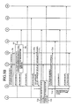
- Figs. 5A and 5B show how a failure occurring in the ODN 3 coupled to the primary station equipment unit 1 is dealt with.
- the operations of the primary station equipment unit 1 and the secondary station equipment units 2-1-2-n occurring in the event of a failure are illustrated along a time line extending in a downward direction in the drawing.
- the primary station line termination 4 for the active system is referred to as the primary station line termination 4 for system A
- the primary station line termination 5 for the standby system is referred to as the primary system signal termination 5 for system B.
- a failure hereinafter, referred to as a trunk failure
- the 2-1 selector 11 and the route setting unit 12 select the main signal from the secondary station line termination 6 for the active system and the 2-1 selector 31 and the route setting unit 32 select the main signal from the primary station line termination 4 for system A.
- the main signal is transmitted and received over system A.
- each of the secondary station equipment units 2-1-2-n detects the failure (for example, LOS: loss of signal in the secondary station equipment unit) corresponding to the secondary station line termination 6 for the active system (T22a, T22b, T22n).
- the failure for example, LOS: loss of signal in the secondary station equipment unit
- the secondary station line termination 6 of the secondary station equipment units 2-1-2-n acknowledges the failure in the active system after a predetermined guard time (TW1, TW2, TWn) so as to execute a redundant switching sequence (T23a, T23b, T23n).
- a passive optical network communications system that complies with ITU-T Recommendation G. 983.1 is configured to stop the transmission to the primary station equipment unit 1 after the secondary station equipment units 2-1-2-n detect a failure in a transmission path. Therefore, the primary station equipment unit 1 also detects the transmission failure corresponding to the secondary station equipment units 2-1-2-n. At this stage, the primary station line termination 4 of system A does not detect the failure corresponding to the secondary station equipment units 2-1-2-n (T24a, T24b, T24n). Since a redundancy switching sequence is being executed in response to a request from the secondary station equipment units 2-1-2-n, the failure detected by the primary station equipment unit 1 after a predetermined period of guard time TW is neglected (T25).
- the selective control unit 33 of the secondary station equipment unit 2-1 Since the selective control unit 33 of the secondary station equipment unit 2-1 detected the failure in the active system, it updates the PST message so as to include the K1 byte indicating that "switching is being requested due to signal fail (SF)" and the K2 byte indicating that "the active system is being selected” (T26a).
- the primary station equipment unit 1 transmits the PLOAM grant (PLOAM cell transmission enable signal) to the secondary station equipment units 2-1-2-n at predetermined intervals so as to receive the PLOAM (physical layer operation and management) cells from the secondary station equipment units 2-1-2-n.
- PLOAM grant PLOAM cell transmission enable signal
- ITU-T Recommendation G. 983.1 recommends that the primary station equipment unit 1 and the secondary station equipment units 2-1-2-n transmit the PST message at predetermined intervals (for example, one message per second).
- the selective control unit 33 of the secondary station equipment unit 2-1 outputs the PST message, comprising the K1 byte indicating that "switching is being requested due to signal fail (SF)" and the K2 byte indicating that "the active system is being selected", to the PLOAM cell composing units 34 and 35 for the active system and the standby system, respectively.
- the transmission of the message by the transceivers 38 and 39 of the secondary station equipment unit 2-1 to the primary station equipment unit 1 is deferred until T27a when the PLOAM grant is received (T28a).
- the transceiver 19 of the primary station equipment unit 1 receives the PLOAM cell including the PST message (since the trunk failure occurs in the active system, the PLOAM cell does not arrive at the transceiver 18).
- the PLOAM cell decomposing unit 21 outputs the PST message included in the PLOAM cell to the selective control unit 13.
- the selective control unit 13 of the primary station equipment unit 1 controls the route setting unit 12, based on the PST message.
- the selective control unit 13 Since the K1 byte received from the secondary station equipment unit 2-1 indicates that "switching is being requested due to signal fail (SF)", the selective control unit 13 outputs an instruction directing the route setting unit 12 to be switched to system B (T29a).
- the selective control unit 13 of the primary station equipment unit 1 Since the selective control unit 13 of the primary station equipment unit 1 has acknowledged the failure corresponding to the secondary station equipment unit 2-1, it updates the PST message so as to include the K1 byte indicating "acknowledgement" and the K2 byte indicating "system A is being selected” (T30a).
- the selective control unit 13 of the primary station equipment unit 1 outputs the PST message, comprising the K1 byte indicating "acknowledgement" and the K2 byte indicating that "system A is being selected", to the PLOAM cell composing units 14 and 15 for system A and system B, respectively.
- the PLOAM cell including the PST message is transmitted by the transceivers 18 and 19 of the primary station equipment unit 1 to the secondary station equipment unit 2-1.
- the transceiver 39 of the secondary station equipment unit 2-1 receives the PLOAM cell.
- the PLOAM cell decomposing unit 41 outputs the PST message included in the PLOAM cell to the selective control unit 33 (T31a).
- the selective control unit 33 of the secondary station equipment unit 2-1 controls the 2-1 selector 31 and the route setting unit 32, based on the PST message.
- the selective control unit 33 Since the K1 byte received indicates "acknowledgement", the selective control unit 33 outputs an instruction directing the 2-1 selector 31 and the route setting unit 32 to be switched to the standby system (T32a, T33a).
- the selective control unit 33 of the secondary station equipment unit 2-1 updates the PST message so as to include the K1 byte indicating that "switching is being requested due to signal fail (SF)" and the K2 byte indicating that "the standby system is being selected”.
- the selective control unit 33 outputs the PST message thus updated to the PLOAM cell decomposing units 34 and 35 for the active system and the standby system, respectively (T34a).
- the transmission of the PLOAM cell including the PST message from the transceiver 39 of the secondary station equipment 2-1 to the primary station equipment unit 1 is deferred until T35a when the PLOAM grant is received.
- the PLOAM cell including the PST message is received by the transceiver 19 of the primary station equipment unit 1, where the PLOAM cell decomposing unit 21 outputs the PST message included in the PLOAM cell to the selective control unit 13 (T36a).
- the selective control unit 13 of the primary station equipment unit 1 controls the 2-1 selector 11, based on the PST message.
- the selective control unit 13 Since the K2 byte received indicates that "the standby system is being selected", the selective control unit 13 outputs an instruction directing the 2-1 selector 11 to be switched to system B (T37a). Subsequently, the main signal is transmitted and received over the standby system and system B.
- the selective control unit 13 of the primary station equipment unit 1 updates the PST message so as to include the K1 byte indicating "acknowledgement” and the K2 byte indicating that "system B is being selected” to the PLOAM cell composing units 14 and 15 (T38a).
- the PLOAM cell including the PST message is transmitted by the transceivers 18 and 19 of the primary station equipment to the secondary station equipment unit 2-1 (T39a).
- the PLOAM cell is received by the transceiver 39 of the secondary station equipment unit 2-1 where the PLOAM cell decomposing unit 41 outputs the PST message included in the PLOAM cell to the selective control unit 33, thus completing a redundancy switching sequence.
- the other secondary station line terminations 2-2, 2-n simultaneously detect failures (for example, LOS) corresponding to the secondary station line terminations 6-2, 6-n for the active system.
- the secondary station equipment units 2-2, 2-n perform redundancy switching in accordance with the timing designated by the PLOAM grant from the primary station equipment unit 1 (T26b-T39b, T26n-T39n).
- the primary station equipment unit 1 transmits the PLOAM grant (PLOAM cell transmission enable signal) to the secondary station equipment units 2-1-2-n at predetermined intervals.
- the secondary station equipment units 2-1-2-n transmit the PST message to the primary station equipment unit 1 in accordance with the timing designated by the PLOAM grant.
- the configuration described above generates a queuing time in which each of the secondary station equipment units 2-1-2-n has to wait for the reception of the PLAOM grant. Thus, a relatively long period of time is required for redundancy switching.
- a failure occurring in the trunk portion of the ODN 3 is processed such that the secondary station equipment units 2-1-2-n detect the failure earlier than the primary station equipment unit 1. Therefore, the primary station equipment unit 1 responds individually to a redundancy switching request from each of the secondary station equipment units to perform individual redundancy switching processes. As a result, a relatively long period of time is required before redundancy switching is completed for the entirety of the secondary station equipment units 2-1-2-n.
- the present invention has been developed in order to resolve the aforementioned problems and has an objective of providing a passive optical network communications system in which a time required for redundancy switching for the secondary station equipment units is reduced.
- a primary station equipment unit transmits, to a secondary station equipment unit, a message transmission enable signal granting transmission of an upstream message from the secondary station equipment unit, when a predetermined period of time defined for transmission elapses after the primary station equipment unit transmitted a downstream message in a redundancy switching process.
- the primary station equipment unit repeats the transmission of the message transmission enable signal each time a predetermined period of time for transmission elapses until the upstream message is received from the secondary station equipment unit.
- the primary station equipment unit learns, when performing the redundancy switching process corresponding to the secondary station equipment unit, redundancy switching processing time, which is a time required for the secondary station equipment unit to perform the redundancy switching process, so as to adjust the timing for transmission to the secondary station equipment unit.
- the primary station equipment unit initializes the redundancy switching processing time when a predetermined condition is met.
- the primary station equipment unit transmits a message transmission enable signal to the secondary station equipment unit granting transmission of an upstream message from the secondary station equipment unit, a period of transmission of the message transmission enable signal to the secondary station equipment unit for a standby system being shorter than a period of transmission of the message transmission enable signal to the secondary station equipment unit for an active system.
- the primary station equipment unit when a primary station equipment unit detects a failure corresponding to any of a plurality of secondary station equipment units, the primary station equipment unit waits until the failures corresponding to the entirety of the plurality of secondary station equipment units are detected, and performs a redundancy switching process for the secondary station equipment unit for which the failure is detected after a predetermined period of time.
- the primary station equipment performs the redundancy switching process for the secondary station equipment units for which the failure is detected in a single series of steps.
- the primary station equipment unit waits until the upstream messages are received from the secondary station equipment units for each of which the failure is detected, so that the redundancy switching processes for the secondary station equipment units are executed in a single series of steps.
- the primary station equipment unit detects a failure corresponding to the secondary station equipment unit and starts a redundancy switching process after a guard time which is shorter than a guard time of the secondary station equipment unit.
- Fig. 6 shows a configuration of a passive optical network communications system according to a first embodiment of the present invention.
- the system comprises a primary station equipment unit 51, secondary station equipment units 52-1-52-n, an optical distribution network (ODN) 53 implemented by passive elements such as optical couplers and optical fibers, a primary station line termination 54 for an active system, a primary station line termination 55 for a standby system, a secondary station line termination 56 for an active system and a secondary station line termination 57 for a standby system.
- ODN optical distribution network
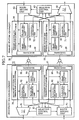
- Fig. 7 shows a detailed configuration of the passive optical network communications system according to the first embodiment.
- a secondary station equipment unit 52 is one of secondary station equipment units 52-1-52-n.
- a 2-1 selector 61 selectively outputs one of a signal received by the primary station line termination 54 for the active system and the primary station line termination 55 for the standby system, under the direction of a selective control unit 63.
- a route setting unit 62 outputs a main signal to at least one of the primary station line termination 54 for the active system and the primary station line termination 55 for the standby system, under the direction of the selective control unit 63.
- the selective control unit 63 controls the 2-1 selector 61 and the route setting unit 62, based on K1/K2 bytes included in a PON section trace (PST) message, which is a type of physical layer operations administration and maintenance (PLOAM) message.
- PST PON section trace
- PLOAM physical layer operations administration and maintenance
- PLOAM cell composing units 64 and 65 output the PST message output from the selective control unit 63 to transceivers 68 and 69.
- Grant generating units 66 and 67 generate PLOAM grants (PLOAM cell transmission enable signals) so as to output the PLOAM grants thus generated to the transceivers 68 and 69.
- the transceivers 68 and 69 transmit the main signal, the PLOAM cell and the grant to the secondary station equipment unit 52 and also receives the main signal and the PLOAM cell from the secondary station equipment unit 52.
- PLOAM cell decomposing units 70 and 71 receive the PLOAM cell received by the transceivers 68 and 69 and output the PST message to the selective control unit 63.
- a 2-1 selector 81 selects one of a main signal received by a secondary station line termination 56 for an active system and a main signal received by a secondary station line termination 57 for a standby system, under the direction of a selective control unit 83, so as to output the selected signal.
- a route setting unit 82 outputs the main signal to at least one of the secondary station line termination 56 for the active system and the secondary station line termination 57 for the standby system, under the direction of the selective control unit 83.
- the selective control unit 83 controls the 2-1 selector 81 and the route setting unit 82, based on the K1/K2 bytes included in the PST message.
- PLOAM cell composing units 84 and 85 output the PLOAM cell including the PST message, supplied from the selective control unit 83, to the transceivers 88 and 89, the timing of output being indicated by the PLOAM grant detected by grant detecting units 86 and 87.
- the grant detecting units 86 and 87 detect PLOAM grants received by the transceivers 88 and 89.
- the transceivers 88 and 89 transmit the main signal and the PLOAM cell to the primary station equipment unit 51 and also receives the main signal, the PLOAM cell and the grant from the primary station equipment unit 51.
- PLOAM cell decomposing units 90 and 91 receive the main signal received by the transceivers 88 and 89 so as to output the PST message to the selective control unit 83.
- Fig. 8 shows an example of control effected when a failure occurs in the secondary station equipment unit 5-1.
- the operations of the primary station equipment unit 51 and the secondary station equipment units 52-1-52-n performed in the event of a failure are illustrated along a time line extending in a downward direction in the drawing.
- the 2-1 selector 61 and the route setting unit 62 select the main signal from the secondary station line termination 56 for the active system and that the 2-1 selector 81 and the route setting unit 82 select the main signal from the primary station line termination 54 for the active system.
- the main signal is transmitted and received over the active system.
- the selective control unit 83 of the secondary station equipment unit 52-1 outputs a PST message, comprising the K1 byte indicating that "switching is not requested" and the K2 byte indicating that "the active system is being selected", to the PLOAM cell composing units 84 and 85.
- the PLOAM cell including the PST message is transmitted to the primary station equipment unit 51 by the transceivers 88 and 89 of the secondary station equipment unit 52-1.
- the PLOAM cell thus transmitted is received by the transceivers 68 and 69 of the primary station equipment unit 51 where the PLOAM cell decomposing units 70 and 71 output the PST message included in the PLOAM cell to the selective control unit 63.
- the selective control unit 63 of the primary station equipment unit 51 controls the 2-1 selector 61 and the route setting unit 62, based on the PST message thus received.
- the primary station equipment unit 51 also transmits the PST message, comprising the K1 byte and the K2 byte, to the secondary station equipment unit 52-1.
- the primary station equipment unit 51 does not undergo any failure so that the K1 byte indicating that "switching is not requested" continues to be transmitted to the secondary station equipment unit 52-1.
- the selective control unit 83 of the secondary station equipment unit 52-1 updates the PST message so as to include the K1 byte indicating that "switching is being requested due to signal fail (SF)" and the K2 byte indicating that "the active system is being selected”.
- the selective control unit 83 outputs the PST message thus updated to the PLOAM cell composing units 84 and 85 (T2).
- the PLOAM cell including the PST message is transmitted to the primary station equipment unit 51 by the transceivers 68 and 69 of the secondary station equipment unit 52-1.
- the transceiver 69 of the primary station equipment unit 51 receives the PLOAM cell (the PLOAM cell does not arrive at the transceiver 68 since the failure occurred in the active system).
- the PLOAM cell decomposing unit 71 outputs the PST message included in the PLOAM cell to the selective control unit 63 (T3).
- the selective control unit 63 of the primary station equipment unit 51 receiving the PST message from the PLOAM cell decomposing unit 71 controls the route setting unit 62, based on the PST message.
- the selective control unit 63 Since the K1 byte received indicates that "switching is being requested due to signal fail (SF)", the selective control unit 63 outputs an instruction directing the route setting unit 62 to be switched to system B (T4).
- the primary station equipment unit 51 updates the K1 byte so as to indicate "acknowledgement” (T5) since it has acknowledged that a failure occurred in the secondary station equipment unit 52-1.
- the selective control unit 63 of the primary station equipment unit 51 outputs the PST message, comprising the K1 byte indicating "acknowledgement" and the K2 byte indicating that "the active is being selected", to the PLOAM cells composing units 64 and 65.
- the PLOAM cell including the PST message is transmitted by the transceivers 68 and 69 of the primary station equipment unit 51 to the secondary station equipment unit 52-1.
- the PLOAM cell is received by the transceiver 89 of the secondary station equipment unit 52-1 where the PLOAM cell decomposing unit 91 outputs the PST message included in the PLOAM cell to the selective control unit 83 (T6).
- the selective control unit 83 of the secondary station equipment unit 52-1 controls the 2-1 selector 81 and the route setting unit 82, based on the PST message.
- the selective control unit 83 Since the K1 byte received indicates "acknowledgement", the selective control unit 83 outputs an instruction directing the 2-1 selector 81 and the route setting unit 82 to be switched to the standby system (T7).
- the selective control unit 83 of the secondary station equipment unit 52-1 updates the PST message so as to include the K1 byte indicating that "switching is being requested due to signal fail (SF)" and the K2 byte indicating that "the standby system is being selected", so as to output the PST message thus updated to the PLOAM cell composing units 84 and 85 (T8).
- the selective control unit 63 of the primary station equipment unit 51 After outputting the PST message at T6, the selective control unit 63 of the primary station equipment unit 51 sends the PLOAM grant after a predetermined period of time (Tw) elapses so as to receive the PST message from the secondary station equipment units 52-1 (T9, T10).
- the selective control unit 83 of the secondary station equipment unit 52-1 outputs the PST message, comprising the K1 byte indicating that "switching is being requested due to signal fail (SF)" and the K2 byte indicating that "the standby system is being selected", to the PLOAM cell composing units 84 and 85, the output being timed in accordance with the reception of the PLOAM grant at T10.
- the PLOAM cell including the PST message is received by the transceiver 69 of the primary station equipment 51 where the PLOAM cell decomposing unit 71 outputs the PST message included in the PLOAM cell to the selective control unit 63 (T11).
- the selective control unit 63 of the primary station equipment unit 51 receiving the PST message from the PLOAM cell decomposing unit 71 controls the 2-1 selector 61, based on the PST message.
- the selective control unit 63 Since the K2 byte received from the secondary station equipment unit 52-1 indicates that "the standby system is being selected", the selective control unit 63 outputs an instruction directing the 2-1 selector 61 to be switched to the standby system (T12). Subsequently, the main signal is transmitted and received over the standby system.
- the selective control unit 63 of the primary station equipment unit 51 updates the PST message so as to include the K1 byte indicating "acknowledgement" and the K2 byte indicating that "the standby system is being selected”.
- the selective control unit 63 outputs the PST message to the PLOAM cell composing units 64 and 65 (T13).
- the PLOAM cell including the PST message is transmitted to the secondary station equipment unit 52-1 by the transceivers 68 and 69 of the primary station equipment unit (T14).
- the transceiver 89 of the secondary station equipment unit 52-1 receives the PLOAM cell.
- the PLOAM cell decomposing unit 91 outputs the PST message included in the PLOAM cell to the selective control unit 83, thus completing a redundancy switching sequence.
- the PLOAM grant from the primary station equipment unit 51 is used for the transmission of the other PLOAM cells that are waiting. It is that expected that the target PST message is placed in a standby state in which it has to stand by for the transmission. Accordingly, the selective control unit 63 of the primary station equipment unit 51 repeats the transmission of the PLOAM grant at predetermined intervals (Tw) until the target PST message is received from the secondary station equipment unit 52-1 (not shown).
- the secondary station equipment 52-1 receives the PLOAM grant (PLOAM cell transmission enable signal) from the primary station equipment unit 51 to enable the transmission of the PST message at T11. Accordingly, queueing time required to stand by for the transmission of the PST message is ensured to be reduced so that the time required for the whole process of redundancy switching is successfully reduced.
- PLOAM grant PLOAM cell transmission enable signal
- the time (T6-T8) required for redundancy switching process in the secondary station 52-1 varies depending on the performance of the secondary station equipment unit 52-1 (i.e. it differs from vendor to vendor).
- the primary station equipment unit 51 learns the time required for the redundancy switching process in the secondary station equipment unit 52 connected thereto in consideration of the multi-vendor connection possibly implemented between the primary station equipment unit 51 and the secondary station equipment unit 52.
- the timing of transmission of the PLOAM grant is adjusted in accordance with the time thus learned.
- the primary station equipment unit initially generates the PLOAM grant at predetermined intervals (Tw).
- Tw predetermined period time
- the primary station equipment unit waits for the predetermined period time (Tw) again before generating the PLOAM grant.
- the primary station equipment unit learns the time it takes to receive the expected PST message from the secondary station equipment unit 52-1. Generation of excessive number of PLOAM grants is prevented by generating the PLOAM grant after the learned time elapses in subsequent instances of redundancy switching. Thereby, the time required for the whole process of redundancy switching is reduced.
- the primary station equipment unit 51 is operated on the assumption that the secondary station equipment unit 52-1 may be switched to that of a different vendor. For this reason, the time learned as described above is reset at each instance of ranging (1), FSAN number change (2), and secondary station equipment unit registration. In a POPUP procedure (3), the learned time is not reset. As a result of this operation in the primary station equipment unit 51, generation of the PLOAM grants is timed optimally when the secondary station equipment unit is switched to that of a different vendor. Thus, the time required for the whole process of redundancy switching is reduced.
- redundancy switching in the secondary station equipment unit 52 is configured such that, when a predetermined period of time elapses after the primary station equipment unit 51 transmits the PST message to the secondary station equipment unit 52, the PLOAM grant (PLOAM cell transmission enable signal) granting the transmission of the upstream PST message from the secondary station equipment unit 52 is transmitted to the secondary station equipment unit 52. Accordingly, the time required for redundancy switching in the secondary station equipment unit 52 is reduced.
- the PLOAM grant granting the transmission of the upstream PST message from the secondary station equipment unit 52 is transmitted to the secondary station equipment unit 52.
- the first example of related art in which primary station equipment unit 51 transmits the PLOAM grant to the secondary station equipment unit 52.
- the interval of transmission from the primary station equipment unit 51 to the secondary station equipment unit for the standby system may be configured to be shorter than that of the transmission to the secondary station equipment unit 52 for the active system (the secondary station line termination 56 for the active system).
- system according to the second embodiment is configured as follows.
- Figs. 9A and 9B show an example of control effected when a failure occurs in the secondary station equipment unit 52-1.
- the operations of the primary station equipment unit 51 and the secondary station equipment units 52-1-52-n performed in the event of a failure are illustrated along a time line extending in a downward direction in the drawing.
- the primary station line termination 54 for the active system is referred to as the primary station line termination 54 for system A
- the primary station line termination 55 for the standby system is referred to as the primary system signal termination 55 for system B.
- the 2-1 selector 61 and the route setting unit 62 select the main signal from the secondary station line termination 56 for the active system and that the 2-1 selector 81 and the route setting unit 82 select the main signal from the primary station line termination 54 for system A.
- the main signal is transmitted and received over the active system.
- the selective control unit 83 of the secondary station equipment unit 52-1 outputs a PST message, comprising the K1 byte indicating that "switching is not requested" and the K2 byte indicating that "the active system is being selected", to the PLOAM cell composing units 84 and 85.
- the PLOAM cell including the PST message is transmitted to the primary station equipment unit 51 by the transceivers 88 and 89 of the secondary station equipment unit 52-1.
- the PLOAM cell thus transmitted is received by the transceivers.68 and 69 of the primary station equipment unit 51 where the PLOAM cell decomposing units 70 and 71 output the PST message included in the PLOAM cell to the selective control unit 63.
- the selective control unit 63 of the primary station equipment unit 51 controls the 2-1 selector 61 and the route setting unit 62, based on the PST message thus received.
- the primary station equipment unit 51 also transmits the PST message, comprising the K1 byte and the K2 byte, to the secondary station equipment unit 52-1.
- the primary station equipment unit 51 does not undergo any failure so that the K1 byte indicating that "switching is not requested" continues to be transmitted to the secondary station equipment unit 52-1.
- the selective control unit 83 of the secondary station equipment unit 52-1 updates the PST message so as to include the K1 byte indicating that "switching is being requested due to signal fail (SF)" and the K2 byte indicating that "the active system is being selected”.
- the selective control unit 83 outputs the PST message thus updated to the PLOAM cell composing units 84 and 85 (T2).
- the primary station equipment unit 51 transmits PLOAM grants (PLOAM cell transmission enable signals) to the secondary station equipment units 52-1-52-n at predetermined intervals so as to receive PLOAM cells from the secondary station equipment units 52-1-52-n (T0a1, T0b1, T0a2, T0b2, T0an, T0bn).
- PLOAM grants PLOAM cell transmission enable signals
- a period of transmission TW2 of PLOAM grants from system B is configured to be shorter than a period of transmission TW1 of PLOAM grants from system A so that the frequency of generation of PLOAM grants in system B is larger (T9, T10).
- the selective control unit 83 of the secondary station equipment unit 52-1 outputs the PST message, comprising the K1 byte indicating that "switching is being requested due to signal fail (SF)" and the K2 byte indicating that "the active system is being selected", to the PLOAM cell composing units 84 and 85.
- the transmission of the PST message to the primary station equipment unit 51 is deferred until T70 when the PLOAM grant is received.
- the PLOAM cell including the PST message is transmitted to the primary station equipment unit 51 by the transceivers 88 and 89 of the secondary station equipment unit 52-1.
- the transceiver 69 of the primary station equipment unit 51 receives the PLOAM cell (the PLOAM cell does not arrive at the transceiver 68 since the failure occurred in the active system).
- the PLOAM cell decomposing unit 71 outputs the PST message included in the PLOAM cell to the selective control unit 63 (T3).
- the selective control unit 63 of the primary station equipment unit 51 receiving the PST message from the PLOAM cell decomposing unit 71 controls the route setting unit 62, based on the PST message.
- the selective control unit 63 Since the K1 byte received from the secondary station equipment unit 52-1 indicates that "switching is being requested due to signal fail (SF)", the selective control unit 63 outputs an instruction directing the route setting unit 62 to be switched to system B (T4).
- the primary station equipment unit 51 updates the K1 byte so as to indicate "acknowledgement” (T5) since it has acknowledged that a failure occurred in the secondary station equipment unit 52-1.
- the selective control unit 63 of the primary station equipment unit 51 outputs the PST message, comprising the K1 byte indicating "acknowledgement" and the K2 byte indicating that "system A is being selected", to the PLOAM cells composing units 64 and 65.
- the PLOAM cell including the PST message is transmitted by the transceivers 68 and 69 of the primary station equipment unit 51 to the secondary station equipment unit 52-1.
- the transceiver 89 of the secondary station equipment unit 52-1 receives the PLOAM cell.
- the PLOAM cell decomposing unit 91 outputs the PST message included in the PLOAM cell to the selective control unit 83 (T6).
- the selective control unit 83 of the secondary station equipment unit 52-1 controls the 2-1 selector 81 and the route setting unit 82, based on the PST message.
- the selective control unit 83 Since the K1 byte received indicates "acknowledgement", the selective control unit 83 outputs an instruction directing the 2-1 selector 81 and the route setting unit 82 to be switched to the standby system (T7).
- the selective control unit 83 of the secondary station equipment unit 52-1 updates the PST message so as to include the K1 byte indicating that "switching is being requested due to signal fail (SF)" and the K2 byte indicating that "the standby system is being selected", so as to output the PST message thus updated to the PLOAM cell composing units 84 and 85 (T8).
- the transmission of the PLOAM cell including the PST message from the transceivers 88 and 89 of the secondary station equipment unit 52-1 to the primary station equipment unit 51 is deferred until T71 when the PLOAM grant is received.
- the transceiver 69 of the primary station equipment unit 51 receives the PLOAM cell.
- the PLOAM cell decomposing unit 71 outputs the PST message included in the PLOAM cell to the selective control unit 63 (T11).
- the selective control unit 63 of the primary station equipment unit 51 receiving the PST message from the PLOAM cell decomposing unit 71 controls the 2-1 selector 61, based on the PST message.
- the selective control unit 63 Since the K2 byte received from the secondary station equipment unit 52-1 indicates that "the standby system is being selected", the selective control unit 63 outputs an instruction directing the 2-1 selector 61 to be switched to system B (T12). Subsequently, the main signal is transmitted and received over the standby system and system B.
- the selective control unit 63 of the primary station equipment unit 51 updates the PST message so as to include the K1 byte indicating "acknowledgement" and the K2 byte indicating that "system B is being selected”.
- the selective control unit 63 outputs the PST message to the PLOAM cell composing units 64 and 65 (T13).
- the PLOAM cell including the PST message is transmitted to the secondary station equipment unit 52-1 by the transceivers 68 and 69 of the primary station equipment unit (T14).
- the transceiver 89 of the secondary station equipment unit 52-1 receives the PLOAM cell.
- the PLOAM cell decomposing unit 91 outputs the PST message included in the PLOAM cell to the selective control unit 83, thus completing a redundancy switching sequence.
- a PLOAM transmission period (TW2) for transmission of PLOAM grants from the primary station line termination 55 for system B to the secondary station line termination 57 for the standby system is changed to a PLOAM transmission period (TW1) used in system A so that the transmission of the main signal is not interfered with (T15).
- the period of transmission of PLOAM grants from system B is configured to be shorter than that of system B.
- undesired transmission queuing time in which the secondary station equipment unit has to stand by for the reception of the PLOAM grant after the secondary station equipment unit 52-1 updated the PST message is reduced. Therefore, the time required for the whole process of redundancy switching is reduced.
- Figs. 10A and 10B show an example of control effected when a failure is detected in the ODN 53 coupled to the primary station equipment unit 51.
- the operations of the primary station equipment unit 51 and the secondary station equipment units 52-1-52-n performed in the event of a failure are illustrated along a time line extending in a downward direction in the drawing.
- a failure hereinafter, referred to as a trunk failure
- the 2-1 selector 61 and the route setting unit 62 select the main signal from the secondary station line termination 56 for the active system and the 2-1 selector 81 and the route setting unit 82 select the main signal from the primary station line termination 54 for the active system.
- the main signal is transmitted and received over the active system.
- the primary station line termination 54 for the active system in the primary station equipment unit 51 detects a failure (for example, LOSi: loss of signal) corresponding to the secondary station equipment unit 52-1 (T22a).
- the selective control unit 63 of the primary station equipment unit 51 operates on the assumption that failures corresponding to the other secondary station equipment units 52-2-52-n may simultaneously occur.
- the count of a queuing timer is started to wait for a predetermined period of time (T23) until the failures corresponding to the other secondary stations (T24a) are detected.
- the selective control unit 63 of the primary station equipment unit 51 waits until the failures corresponding to the entirety of secondary station equipment units are detected (T24b, T24n).
- the selective control unit 63 of the primary station equipment unit 51 stops the queuing timer (T25) so as to start a redundancy switching operation.
- the selective control unit 63 of the primary station equipment unit 51 detecting the trunk failure in the active system outputs an instruction directing the route setting unit 62 to be switched to the standby system (T26a, T26b, T26n).
- the selective control unit 63 of the primary station equipment unit 51 Since the selective control unit 63 of the primary station equipment unit 51 detected the failures corresponding to the secondary station equipment units 52-1, 52-2, 52-n, it updates the PST message so as to include the K1 byte indicating that "switching is being requested due to signal fail (SF)" and the K2 byte indicating that "the active system is being selected" (T27a, T27b, T27n).
- the selective control unit 63 of the primary station equipment unit 51 outputs the PST message, comprising the R1 byte indicating that "switching is being requested due to signal fail (SF)" and the K2 byte indicating that "the active system is being selected", to the PLOAM cell composing units 64 and 65.
- the PLOAM cell including the PST message is transmitted to the secondary station equipment units 52-1, 52-2, 52-n by the transceivers 68 and 69 of the primary station equipment unit 51.
- the transceiver 89 of the secondary station equipment units 52-1, 52-2, 52-n receives the PLOAM cell (the PLOAM cell does not arrive at the transceiver 88 since the failure occurred in the active system).
- the PLOAM cell decomposing unit 91 outputs the PST message included in the PLOAM cell to the selective control unit 83 (T28a, T28b, T28n).
- the selective control unit 83 of the secondary station equipment units 52-1, 52-2, 52-n receiving the PST message from the PLOAM cell decomposing unit 91 controls the 2-1 selector 81 and the route setting unit 82, based on the PST message.
- the selective control unit 83 Since the K1 byte received indicates that "switching is being requested due to signal fail (SF)", the selective control unit 83 outputs an instruction directing the 2-1 selector 81 and the route setting unit 82 to be switched to the standby system (T29a-T30a, T29b-T30b, T29n-T30n).
- the selective control unit 83 of the secondary station equipment units 52-1, 52-2, 52-n Since the selective control unit 83 of the secondary station equipment units 52-1, 52-2, 52-n has acknowledged the detection of a failure by the primary station equipment unit 51, the selective control unit 83 updates the PST message so as to include the K1 byte indicating "acknowledgement" and the K2 byte indicating that "the standby system is being selected". The selective control unit 83 outputs the PST thus updated to the PLOAM cell composing units 84 and 85 (T31a, T31b, T31n).
- the selective control unit 63 of the primary station equipment unit 51 sends PLOAM grants after a predetermined period of time (Tw) elapses so as to receive the PST message from the secondary station equipment units 52-1, 52-2, 52-n (T32a-T33a, T32b-T33b, T32n-T33n).
- the selective control unit 83 of the secondary station equipment units 52-1, 52-2, 52-n outputs the PST message including the K1 byte indicating "acknowledgement" and the K2 byte indicating that "the standby system is being selected" to the PLOAM cell composing units 84 and 85 (T34a, T34b, T34n).
- the PLOAM cell including the above PST message is received by the transceiver 69 of the primary station equipment unit 51, where the PLOAM cell decomposing unit 71 outputs the PST message included in the PLOAM cell to the selective control unit 63 (T34a, T34b, T34n).
- the selective control unit 63 of the primary station equipment unit 51 receiving the PST message from the PLOAM cell decomposing unit 71 controls the 2-1 selector 61, based on the PST message.
- the selective control unit 63 Since the K2 byte received indicates that "the standby system is being selected", the selective control unit 63 outputs an instruction directing the 2-1 selector 61 to be switched to the standby system (T35a, T35b, T35n). Subsequently, the main signal is transmitted and received over the standby system.
- the selective control unit 63 of the primary station equipment unit 51 updates the PST message so as to include the K1 byte indicating "switching is being requested due to signal fail (SF)" and the K2 byte indicating that "the standby system is being selected”.
- the selective control unit 63 outputs the PST message to the PLOAM cell composing units 64 and 65 (T36a, T36b, T36n).
- the PLOAM cell including the PST message is transmitted to the secondary station equipment units 52-1, 52-2, 52-n by the transceivers 68 and 69 of the primary station equipment unit 51.
- the transceiver 89 of the secondary station equipment units 52-1, 52-2, 52-n receives the PLOAM cell.
- the PLOAM cell decomposing unit 91 outputs the PST message included in the PLOAM cell to the selective control unit 83, thus completing a redundancy switching sequence (not shown).
- the primary station equipment unit 51 is prevented from performing redundancy switching whenever a failure is detected at T24a-T24. Instead, the primary station equipment unit 51 is configured to wait for the detection of the failures of the other secondary station equipment units 52-2-52-n so that the redundancy switching process is started only when the failures corresponding to the entirety of the registered secondary station equipment units 52-2-52-n are detected or when the predetermined period of time (TW) elapses. Accordingly, the time required for the whole process of redundancy switching is reduced.
- TW predetermined period of time
- the primary station equipment unit 51 is configured to perform a single series (T26a-T26n) of steps for redundancy switching for the entirety of secondary station equipment units including the equipment units 52-2-52-n, the time required for the whole process of redundancy switching is further reduced.
- Figs. 11A and 11B show an example of control effected when a failure is detected in the ODN 53 coupled to the primary station equipment unit 51.
- the operations of the primary station equipment unit 51 and the secondary station equipment units 52-1-52-n performed in the event of a failure are illustrated along a time line extending in a downward direction in the drawing.
- a failure hereinafter, referred to as a trunk failure
- the 2-1 selector 61 and the route setting unit 62 select the main signal from the secondary station line termination 56 for the active system and the 2-1 selector 81 and the route setting unit 82 select the main signal from the primary station line termination 54 for the active system.
- the main signal is transmitted and received over the active system.
- the primary station line termination 54 for the active system in the primary station equipment unit 51 waits for the detection of the failures corresponding to the entirety of the secondary station equipment units 52-1-52-n (T22a-T27n), in a similar configuration as the third embodiment.
- the selective control unit 63 of the primary station equipment unit 51 outputs the PST message, comprising the K1 byte indicating that "switching is being requested due to signal fail (SF)" and the K2 byte indicating that "the active system is being selected", to the PLOAM cell composing units 64 and 65 in a similar configuration as the third embodiment.
- the PLOAM cell including the PST message is transmitted to the secondary station equipment units 52-1, 52-2, 52-n by the transceivers 68 and 69 of the primary station equipment unit 51.
- the transceiver 89 of the secondary station equipment units 52-1, 52-2, 52-n receives the PLOAM cell (the PLOAM cell does not arrive at the transceiver 88 since the failure occurred in the active system).
- the PLOAM cell decomposing unit 91 outputs the PST message included in the PLOAM cell to the selective control unit 83 (T28a, T28b, T28n).
- the selective control unit 63 of the primary station equipment unit 51 starts the count of a queuing timer (T41) so as to wait for a predetermined period of time before receiving the PST messages from the entirety of the secondary station equipment units 52-1-52-n connected to the primary station line termination 54 for the active system of the primary station equipment unit 51.
- the selective control unit 63 waits for the PST messages to arrive from the entirety of the secondary station equipment units 52-1-52-n.
- the selective control unit 83 of the secondary station equipment units 52-1, 52-2, 52-n receiving the PST message from the PLOAM cell decomposing unit 91 controls the 2-1 selector 81 and the route setting unit 82, based on the PST message.
- the PST message for transmission is then updated and transmitted to the primary station equipment unit 51 (T29a-T34n).
- the selective control unit 63 of the primary station equipment unit 51 receiving the PST message from the PLOAM cell decomposing unit 71 waits for the PST messages to arrive from the other secondary station equipment units 52-2-52-n (T42a).
- the selective control unit 63 of the primary station equipment unit 51 stands by for the detection of the failures corresponding to the entirety of the secondary station equipment units (T42b, T42n).
- the selective control unit 63 of the primary station equipment unit 51 stops the queuing timer (T43) so as to start a single series of steps of the redundancy switching process.
- the selective control unit 63 Since the K2 byte received from the secondary station equipment units 52-2-52-n indicates that "the standby system is being selected", the selective control unit 63 outputs an instruction directing the 2-1 selector 61 to be switched to the standby system (T44a, T44b, T44n). Subsequently, the main signal is transmitted and received over the standby system.
- the selective control unit 63 of the primary station equipment unit 51 updates the PST message in a single series of steps so that the PST message includes the K1 byte indicating that "switching is being requested due to signal fail (SF)" and the K2 byte indicating that "the standby system is being selected”.
- the selective control unit 63 outputs the PST messages thus updated to the PLOAM cell composing units 64 and 65 (T45a, T45b, T45n).
- the PLOAM cell including the PST message is transmitted to the secondary station equipment units 52-1, 52-2, 52-n by the transceivers 68 and 69 of the primary station equipment unit 51.
- the PLOAM cell is received by the transceiver 89 of the secondary station equipment units 52-1, 52-2, 52-n where the PLOAM cell decomposing units 90 and 91 outputs the PST message included in the PLOAM cell to the selective control unit 83, thus completing a redundancy switching sequence (not shown).
- the primary station equipment unit 51 is prevented from continuing the redundancy switching process at each reception of the PST message at T42a, T42b, T42n. Instead, the redundancy switching process is continued in a single series of steps after the PST messages are received from the entirety of the secondary station equipment units 52-1-52-n. Accordingly, the time required for the whole process of redundancy switching is reduced as compared to that of the second embodiment.
- Figs. 12A and 12B show an example of control effected when a failure is detected in the ODN 3 coupled to the primary station equipment unit 51.
- the operations of the primary station equipment unit 51 and the secondary station equipment units 52-1-52-n performed in the event of a failure are illustrated along a time line extending in a downward direction in the drawing.
- the primary station line termination 54 for the active system is referred to as the primary station line termination 54 for system A
- the primary station line termination 55 for the standby system is referred to as the primary station line termination 55 for system B.
- a failure hereinafter, referred to as a trunk failure
- the 2-1 selector 61 and the route setting unit 62 select the main signal from the secondary station line termination 56 for the active system and the 2-1 selector 81 and the route setting unit 82 select the main signal from the primary station line termination 54 for system A.
- the main signal is transmitted and received over the active system.
- the secondary station line termination 56 for the active system in the secondary station equipment units 52-1-52-n detects the failure (for example, LOS: loss of signal) (T22a, T22b, T22n).
- the primary station line termination 54 for system A in the primary station equipment unit 51 also detects a failure (for example LOSi: loss of signal) corresponding to the secondary station equipment units 52-1-52-n (T24a, T24b, T24n).
- the redundancy switching sequence is executed when a switching guard time (TW1, TW2, TWn) elapses after the failure is detected.
- the switching guard time TW of the primary station equipment unit 51 is configured to be shorter than the switching guard time TW1, TW2 and TWn of the secondary station equipment units so that the primary station equipment unit 51 initiates the redundancy switching operation (T25, T23a, T23b, T23n).
- the selective control unit 63 of the primary station equipment unit 51 Since the selective control unit 63 of the primary station equipment unit 51 detected the trunk failure in system A, it outputs an instruction directing the route setting unit 62 to be switched to system B (T26a, T26b, T26n).
- the selective control unit 63 of the primary station equipment unit 51 Since the selective control unit 63 of the primary station equipment unit 51 detected the failure corresponding to the secondary station equipment units 52-2-52-n, it updates the PST message so as to include the K1 byte indicating that "switching is being requested due to signal fail (SF)" and the K2 byte indicating that "system A is being selected” (T27a, T27b, T27n).
- the selective control unit 63 of the primary station equipment unit 51 outputs the PST message, comprising the K1 byte indicating that "switching is being requested due to signal fail (SF)" and the K2 byte indicating that "system A is being selected", to the PLOAM cell composing units 64 and 65.
- the PLOAM cell including the PST message is broadcast by the transceivers 68 and 69 of the primary station equipment unit 51 to the secondary station equipment units 52-2-52-n.
- the PLOAM cell is received by the transceiver 89 of the secondary station equipment units 52-2-52-n (the PLOAM cell does not arrive at the transceiver 88 since system A is in failure), where the PLOAM cell decomposing unit 91 outputs the PST message included in the PLOAM cell to the selective control unit 83 (T28).
- the selective control unit 83 of the secondary station equipment units 52-2-52-n receiving the PST message from the PLOAM cell decomposing unit 91 controls the 2-1 selector 81 and the route setting unit 82, based on the PST message.
- the selective control unit 83 Since the K1 byte received indicates that "switching is being requested due to signal fail (SF)", the selective control unit 83 outputs an instruction directing the 2-1 selector 81 and the route setting unit 82 to be switched to the standby system (T29a, T30a, T29b, T30b, T29n, T30n).
- the selective control unit 83 of the secondary station equipment units 52-2-52-n acknowledged the detection of the failure by the primary station equipment unit 51, the selective control unit 83 updates the PST message so as to include the K1 byte indicating "acknowledgement" and the K2 byte indicating that "the standby system is being selected” and outputs the resultant PST message to the PLOAM cell composing units 84 and 85 (T31a, T31b, T31n).
- the primary station equipment unit 51 transmits PLOAM grants (PLOAM cell transmission enable signals) to the secondary station equipment units 52-1-52-n at predetermined intervals so as to receive PLOAM cells from the secondary station equipment units 52-1-52-n (T32a, T32b, T32n).
- PLOAM grants PLOAM cell transmission enable signals
- the selective control unit 83 of the secondary station equipment unit 52-1 outputs the PST message, comprising the K1 byte indicating that "switching is being requested due to signal fail (SF)" and the K2 byte indicating that "acknowledgement", to the PLOAM cell composing units 84 and 85.
- the transmission of the PST message to the primary station equipment unit 51 is deferred until T70 when the PLOAM grant is received at T32a, T32b, T32n.
- the transceiver 69 of the primary station equipment unit 51 receives the PLOAM cell.
- the PLOAM cell decomposing unit 71 outputs the PST message included in the PLOAM cell to the selective control unit 63 (T33a, T33b, T33n).
- the selective control unit 63 of the primary station 51 receiving the PST message from the PLOAM cell decomposing unit 71 waits for the PST messages from the other secondary station equipment units 52-2-52-n (T34a).
- the PST messages from the other secondary station equipment units 52-2-52-n continue to be received (T34b, T34n).
- the selective control unit 63 of the primary station equipment unit 51 receives the PST messages from the entirety of the secondary station equipment units, it resumes the process of redundancy switching in a single series of steps.
- the selective control unit 63 Since the K2 byte received from the secondary station equipment units 52-2-52-n indicates that "the standby system is being selected", the selective control unit 63 outputs an instruction directing the 2-1 selector 61 to be switched to system B (T35a, T35b, T35n). Subsequently, the main signal is transmitted and received over the standby system and system B.
- the selective control unit 63 of the primary station equipment unit 51 updates the PST messages so as to include the R1 byte indicating that "switching is being requested due to signal fail (SF)" and the K2 byte indicating that "system B is being selected” in a single series of steps.
- the selective control unit 63 outputs the resultant PST messages to the PLOAM cell composing units 64 and 65 for system A and system B, respectively (T36a, T36b, T36n).
- the PLOAM cell including the PST message is broadcast to the secondary station equipment units 52-2-52-n by the transceivers 68 and 69 of the primary station equipment unit 51 (T37).
- the PLOAM cell is received by the transceiver 89 of the secondary station equipment units 52-1-52-n where the PLOAM cell decomposing unit 91 outputs the PST message included in the PLOAM cell to the selective control unit 83, thus completing a sequence of redundancy switching.
- the primary station equipment unit 51 is given an initiative in starting the redundancy switching process.
- Each of the secondary station equipment units 52-2-52-n only has to wait once for the PLOAM grant for transmission of the PST message to request the redundancy switching process in the primary station equipment unit 51.
- the primary station equipment unit 51 By enabling the primary station equipment unit 51 to broadcast the PST messages to the secondary station equipment units 52-1-52-n, the time required for the whole process of redundancy switching is reduced.
- Starting the redundancy switching process whenever a failure corresponding to any of the secondary station equipment units 52-2-52-n is detected requires that steps for the preparation of the redundancy switching process (for example, starting of redundancy switching process software and updating of a table) be executed each time. This will result in the time required for the whole process of redundancy switching being extended.
- the preparation of the redundancy switching process in the primary station equipment unit 51 is performed in a single series of steps (T26a-T26n, T27a-T27n) for the entirety of the secondary station equipment units. As a result, the time required for the whole process of redundancy switching is reduced.
- the passive optical network communications system is adapted for requirements for reduction in the processing time for switching the primary station equipment for the active system or the secondary station equipment for the active system to that of the standby system, when a failure occurs in the primary station equipment for the active system or the secondary station equipment for the active system.
Landscapes
- Engineering & Computer Science (AREA)
- Computer Networks & Wireless Communication (AREA)
- Data Exchanges In Wide-Area Networks (AREA)
- Small-Scale Networks (AREA)
Applications Claiming Priority (3)
| Application Number | Priority Date | Filing Date | Title |
|---|---|---|---|
| JP2000382627 | 2000-12-15 | ||
| JP2000382627 | 2000-12-15 | ||
| PCT/JP2001/007493 WO2002049290A1 (fr) | 2000-12-15 | 2001-08-30 | Systeme de communication optique multibranche |
Publications (2)
| Publication Number | Publication Date |
|---|---|
| EP1241836A1 true EP1241836A1 (de) | 2002-09-18 |
| EP1241836A4 EP1241836A4 (de) | 2005-06-01 |
Family
ID=18850421
Family Applications (1)
| Application Number | Title | Priority Date | Filing Date |
|---|---|---|---|
| EP01961219A Ceased EP1241836A4 (de) | 2000-12-15 | 2001-08-30 | Verzweigtes optisches kommunikationssystem |
Country Status (5)
| Country | Link |
|---|---|
| US (1) | US7496294B2 (de) |
| EP (1) | EP1241836A4 (de) |
| JP (1) | JPWO2002049290A1 (de) |
| CN (1) | CN1401174A (de) |
| WO (1) | WO2002049290A1 (de) |
Cited By (1)
| Publication number | Priority date | Publication date | Assignee | Title |
|---|---|---|---|---|
| EP1746857A1 (de) * | 2005-07-20 | 2007-01-24 | Siemens Aktiengesellschaft | Verfahren und Vorrichtung für die Ende-zu-Ende PON-Ausfallsicherheit |
Families Citing this family (6)
| Publication number | Priority date | Publication date | Assignee | Title |
|---|---|---|---|---|
| JP2005045566A (ja) * | 2003-07-23 | 2005-02-17 | Nec Corp | データ通信システム、局側装置、加入者側装置、冗長構成切替判断方法、動作制御方法及びプログラム |
| KR100575945B1 (ko) * | 2003-08-26 | 2006-05-02 | 삼성전자주식회사 | 이중 링크 구조를 갖는 기가비트 이더넷 광가입자망 및이를 이용한 이중 링크 설정방법 |
| WO2008146344A1 (ja) | 2007-05-25 | 2008-12-04 | Mitsubishi Electric Corporation | 光アクセスネットワーク |
| US8582966B2 (en) * | 2007-09-10 | 2013-11-12 | Cortina Systems, Inc. | Method and apparatus for protection switching in passive optical network |
| EP2086136A1 (de) * | 2008-01-29 | 2009-08-05 | British Telecommunications Public Limited Company | Optische Kommunikation |
| JP2010161750A (ja) * | 2009-01-09 | 2010-07-22 | Sony Corp | 信号送信装置、信号受信装置及び信号伝送システム |
Family Cites Families (12)
| Publication number | Priority date | Publication date | Assignee | Title |
|---|---|---|---|---|
| GB2272608B (en) * | 1992-11-12 | 1996-10-09 | Northern Telecom Ltd | Telecommunications systems |
| JP2541463B2 (ja) * | 1993-07-07 | 1996-10-09 | 日本電気株式会社 | インタロッキング装置 |
| US5539564A (en) | 1993-09-22 | 1996-07-23 | Nippon Telegraph And Telephone Corporation | Point-to-multipoint optical transmission system |
| JP3322482B2 (ja) * | 1994-07-06 | 2002-09-09 | 日本電信電話株式会社 | 切替え切戻し装置 |
| JP3432664B2 (ja) * | 1996-02-14 | 2003-08-04 | 富士通株式会社 | 通信ノード及び障害復旧方法並びに通信ネットワーク |
| JPH11122172A (ja) * | 1997-10-20 | 1999-04-30 | Fujitsu Ltd | 光加入者ネットワークシステム |
| US6052210A (en) * | 1998-01-14 | 2000-04-18 | Mci Communications Corporation | System and method for increasing the robustness of an optical ring network |
| JP3350926B2 (ja) | 1999-03-30 | 2002-11-25 | 日本電気株式会社 | Ponのプロテクション切り換え方法および装置 |
| JP2000349799A (ja) * | 1999-06-04 | 2000-12-15 | Nec Corp | Ponシステムにおける冗長構成回路 |
| JP3598952B2 (ja) * | 2000-08-10 | 2004-12-08 | 日本電気株式会社 | Atm−pon二重化システム、局側光網終端装置、加入者側光網終端装置、およびatm−pon二重化方法 |
| JP2002152135A (ja) * | 2000-09-04 | 2002-05-24 | Mitsubishi Electric Corp | 光多分岐通信システム |
| US20020071149A1 (en) * | 2000-12-12 | 2002-06-13 | Xu Dexiang John | Apparatus and method for protection of an asynchronous transfer mode passive optical network interface |
-
2001
- 2001-08-30 WO PCT/JP2001/007493 patent/WO2002049290A1/ja not_active Ceased
- 2001-08-30 EP EP01961219A patent/EP1241836A4/de not_active Ceased
- 2001-08-30 JP JP2002550670A patent/JPWO2002049290A1/ja active Pending
- 2001-08-30 CN CN01805071.9A patent/CN1401174A/zh active Pending
- 2001-08-30 US US10/182,396 patent/US7496294B2/en not_active Expired - Fee Related
Cited By (2)
| Publication number | Priority date | Publication date | Assignee | Title |
|---|---|---|---|---|
| EP1746857A1 (de) * | 2005-07-20 | 2007-01-24 | Siemens Aktiengesellschaft | Verfahren und Vorrichtung für die Ende-zu-Ende PON-Ausfallsicherheit |
| WO2007009949A1 (en) * | 2005-07-20 | 2007-01-25 | Nokia Siemens Networks Gmbh & Co. Kg | Method and apparatus enabling end-to-end resilience in pons |
Also Published As
| Publication number | Publication date |
|---|---|
| JPWO2002049290A1 (ja) | 2004-04-15 |
| WO2002049290A1 (fr) | 2002-06-20 |
| US7496294B2 (en) | 2009-02-24 |
| CN1401174A (zh) | 2003-03-05 |
| US20030002114A1 (en) | 2003-01-02 |
| EP1241836A4 (de) | 2005-06-01 |
Similar Documents
| Publication | Publication Date | Title |
|---|---|---|
| US7609967B2 (en) | Method and apparatus for automatically upgrading passive optical networks (PONs) | |
| EP2245773B1 (de) | Geschütztes passives optisches kommunikationssystem | |
| US9179204B2 (en) | Optical network system | |
| US8538256B2 (en) | Fast protection scheme for passive optical network | |
| US8554080B2 (en) | Failsafe optical splitter and method to isolate faults in a passive optical network | |
| CN101677415B (zh) | 光网络系统数据链路切换方法、光网络单元及系统 | |
| JP2002057679A (ja) | Atm−pon二重化システム、局側光網終端装置、加入者側光網終端装置、およびatm−pon二重化方法 | |
| CN102084665A (zh) | 用于无源光网络的即时保护方案 | |
| CN102104418A (zh) | 传输控制系统、用户侧通信设备和局侧通信设备 | |
| US7274881B2 (en) | Optical line terminal and method that store the identity numbers of a number of optical network terminals that are associated with a single network end point | |
| KR20150100070A (ko) | 수동 광 네트워크에서의 고속 보호 절체 방법 | |
| EP1241836A1 (de) | Verzweigtes optisches kommunikationssystem | |
| CN101150361A (zh) | 一种在无源光网络中实现全保护倒换的方法和系统 | |
| CN101873514B (zh) | 无源光网络保护模式快速切换的方法及系统及光网络单元 | |
| JP4411135B2 (ja) | 2重化ponシステムの親機用送受信装置 | |
| JP2018170572A (ja) | 光通信装置及び波長切替方法 | |
| JP2011004359A (ja) | 光ネットワーク用遅延調整装置 | |
| US12495230B2 (en) | Rangeless failover in PON protection switching | |
| US12580646B2 (en) | Method and apparatus applied to PON system, system, and storage medium | |
| CN117579963A (zh) | 测距方法、测距装置和xpon系统 | |
| JP2003078539A (ja) | 距離測定制御方法とシステム |
Legal Events
| Date | Code | Title | Description |
|---|---|---|---|
| PUAI | Public reference made under article 153(3) epc to a published international application that has entered the european phase |
Free format text: ORIGINAL CODE: 0009012 |
|
| 17P | Request for examination filed |
Effective date: 20020716 |
|
| AK | Designated contracting states |
Kind code of ref document: A1 Designated state(s): AT BE CH CY DE DK ES FI FR GB GR IE IT LI LU MC NL PT SE TR |
|
| RIN1 | Information on inventor provided before grant (corrected) |
Inventor name: IWASAKI, MITSUYOSHI C/O MITSUBISHI DENKI K.K. Inventor name: ICHIBANGASE, HIROSHI,C/O MITSUBISHI DENKI K.K. Inventor name: MUKAI, HIROAKI,C/O MITSUBISHI DENKI K.K. Inventor name: KOZAKI, SEIJI,C/O MITSUBISHI DENKI K.K. Inventor name: TAKEMOTO, MICHIYA,C/O MITSUBISHI DENKI K.K. Inventor name: YOSHIDA, TOSHIKAZU,C/O MITSUBISHI DENKI K.K. Inventor name: ASASHIBA, YOSHIHIRO,C/O MITSUBISHI DENKI K.K. |
|
| RBV | Designated contracting states (corrected) |
Designated state(s): DE FR GB |
|
| RIC1 | Information provided on ipc code assigned before grant |
Ipc: 7H 04L 12/24 B Ipc: 7H 04L 29/14 B Ipc: 7H 04Q 11/00 B Ipc: 7H 04L 12/44 A |
|
| A4 | Supplementary search report drawn up and despatched |
Effective date: 20050419 |
|
| RAP1 | Party data changed (applicant data changed or rights of an application transferred) |
Owner name: MITSUBISHI DENKI KABUSHIKI KAISHA |
|
| 17Q | First examination report despatched |
Effective date: 20050713 |
|
| STAA | Information on the status of an ep patent application or granted ep patent |
Free format text: STATUS: THE APPLICATION HAS BEEN REFUSED |
|
| 18R | Application refused |
Effective date: 20080703 |