EP1241908A1 - Zuweisung von Übertragungskapazitäten in einem Funk-Kommunikationssystem mit Hilfe von adaptiven Antennen - Google Patents
Zuweisung von Übertragungskapazitäten in einem Funk-Kommunikationssystem mit Hilfe von adaptiven Antennen Download PDFInfo
- Publication number
- EP1241908A1 EP1241908A1 EP01106702A EP01106702A EP1241908A1 EP 1241908 A1 EP1241908 A1 EP 1241908A1 EP 01106702 A EP01106702 A EP 01106702A EP 01106702 A EP01106702 A EP 01106702A EP 1241908 A1 EP1241908 A1 EP 1241908A1
- Authority
- EP
- European Patent Office
- Prior art keywords
- terminal
- evaluation
- signaling
- transmitting
- radio signals
- Prior art date
- Legal status (The legal status is an assumption and is not a legal conclusion. Google has not performed a legal analysis and makes no representation as to the accuracy of the status listed.)
- Granted
Links
- 230000006854 communication Effects 0.000 title claims abstract description 60
- 238000004891 communication Methods 0.000 title claims abstract description 60
- 230000005540 biological transmission Effects 0.000 title claims abstract description 35
- 230000003044 adaptive effect Effects 0.000 title claims abstract description 29
- 238000000034 method Methods 0.000 claims abstract description 38
- 238000011156 evaluation Methods 0.000 claims abstract description 32
- 230000011664 signaling Effects 0.000 claims description 24
- 230000000977 initiatory effect Effects 0.000 claims description 14
- 230000000694 effects Effects 0.000 description 5
- 230000005855 radiation Effects 0.000 description 5
- 230000006978 adaptation Effects 0.000 description 3
- 238000012546 transfer Methods 0.000 description 3
- 238000011161 development Methods 0.000 description 2
- 230000007246 mechanism Effects 0.000 description 2
- 238000012545 processing Methods 0.000 description 2
- 238000013459 approach Methods 0.000 description 1
- 230000007175 bidirectional communication Effects 0.000 description 1
- 230000001413 cellular effect Effects 0.000 description 1
- 238000010276 construction Methods 0.000 description 1
- 238000005259 measurement Methods 0.000 description 1
- 238000002360 preparation method Methods 0.000 description 1
- 238000012549 training Methods 0.000 description 1
Images

Classifications
-
- H—ELECTRICITY
- H04—ELECTRIC COMMUNICATION TECHNIQUE
- H04W—WIRELESS COMMUNICATION NETWORKS
- H04W72/00—Local resource management
- H04W72/04—Wireless resource allocation
- H04W72/044—Wireless resource allocation based on the type of the allocated resource
- H04W72/046—Wireless resource allocation based on the type of the allocated resource the resource being in the space domain, e.g. beams
Definitions
- the present invention relates to an assignment method of transmission capacities to a terminal in one Radio communication system, wherein a first transceiver a communication link to the terminal Maintains with the help of adaptive antennas.
- the Invention a base station system of a radio communication system.
- Adaptive antennas can operate in a special mode in particular develop a directionally selective effect.
- directionally selective antennas e.g. be designed in such a way that they are already characterized by the special Training your transmit / receive components a directionally selective Make an impact.
- this is relative low adaptability of the antennas to changing Positions given by moving devices.
- Adaptive antennas offer an improved option in particular a direction-selective effect through a suitable one Control can vary, for example by a Appropriate coordination of multiple transmit / receive components within an antenna on top of each other, i.e. by a so-called Beam forming.
- the use of such antenna systems in radio communication systems is for example from EP 0 786 914 A2 with reference to a directional multiplex radio system (Space Division Multiple Access SDMA). It describes that by appropriate weighting of the received or radiated signals of several antenna elements one Antenna determines a distance metric for the individual devices becomes. Approaches the distance metric defined in this way Terminals like that of another terminal that a clear distinction between the two distance metrics is no longer possible, one of the end devices new transmission capacities made available or performed a handover.
- a disadvantage of such a method is that for the current supply status of the terminal in the supplying transceiver usually a certain Knowledge of the optimal configuration of the antennas to supply the end device, but this knowledge not or only incompletely for the state after the new one Allocation of transmission capacities especially in another transceiver is present. So that can thus according to the methods known from the prior art after the - for example in the context of a handover Allocation of transmission capacity a communication link with the help of adaptive antennas, such as so-called beam forming, not optimal, or even poor or, in the worst case, not being built at all.
- the object of the present invention is therefore one possibility to provide an optimized allocation of Transmission capacities to a terminal allowed, the Advantages of adaptive antennas, especially in their use as directionally selective antennas, as optimal as possible should be exploited.
- the invention comprises a method to assign transmission capacities to a terminal in a radio communication system, being a first Transceiver to a communication link maintains the end device with the help of adaptive antennas.
- the Adaptive antennas can in particular be directionally selective Maintain communication connection to the terminal.
- the interference situation is optimized the transfers from and to the terminal and an appropriate weighting of those sent to the terminal Signals.
- Adaptive antennas can also be used in any other suitable mode, which is not necessarily must have a directionally selective effect.
- a second transmitting / receiving device is directionally selective Evaluates radio signals, which of were sent to the terminal on the basis of this evaluation an allocation of transmission capacities to the terminal carries out and with the help of adaptive antennas a communication link builds up to the terminal.
- Directionally selective communication link to the terminal is built up. It can therefore be an assignment of transmission capacity regardless of knowledge, that in the first transceiver about the configuration the communication link to the terminal. It can therefore be based simply on a simple basis of the radio signals emitted by the end device second transmitting / receiving device can be received, one individually coordinated communication connection to this terminal being constructed.
- the only yardstick here is merely the reception conditions in the second transmitting / receiving device essential.
- the method according to the invention can be used especially for the allocation of transmission capacities in the frame a handover from a first transceiver to a second transceiver.
- the second transceiver has according to the previous procedures before the handover of the terminal not enough knowledge to use adaptive Antennas optimally establish a communication link to be able to set up the terminal.
- the directionally selective evaluation can in principle be carried out by any suitable method, e.g. directionally selective Facilities or suitable procedural steps for a Direction selection can be provided.
- the second transceiver with the help of adaptive Antennas a directionally selective evaluation of the Carry out radio signals, which are sent from the terminal were.
- This has the advantage that no additional facilities necessary in the second transmitting / receiving device are because the directional functionality of the adaptive Antennas especially for building a directionally selective optimized communication link to the Terminal can be provided.
- Such data can, for example, provide information about the parameters of the existing communication link between the Represent terminal and the first transceiver.
- the signaling information about a impending handover of the terminal to the second transceiver contain.
- the second transceiver can already based on this information before a handover based on the directional selection Evaluation preparations for an optimal setup a communication link by using the adaptive Antennas have already been set up accordingly.
- the evaluation of those sent by the terminal Radio signals through signaling on the part of the end device is initiated to the second transceiver.
- the end device itself has more options to influence the allocation of transmission capacities, especially on a handover decision.
- the end device has the best and most current knowledge of the existing ones Has reception conditions at the location of the terminal, can such an initiation by the terminal for more effective Complete the entire process.
- the signaling can contain data that the necessary Method steps in the second transmitting / receiving device can support or steer.
- the Signaling a handover request from the terminal contain the second transceiver. The terminal In such a case, you may even wish for a handover display and so the handover procedures, possibly based on better knowledge of the current reception conditions, start yourself.
- a Data sequence is also used as part of another Signaling is used in the communication system.
- the data sequence is therefore no longer unique in itself, the importance as a trigger for the evaluation must be then from the specific context of use or through other recognition mechanisms.
- This can in particular be provided that a signaling for access to the data system defined data sequence is used.
- the evaluation of the terminal emitted radio signals initiated by a time information becomes.
- Such initiation can then be independent, for example from other units of the communication system alone run within a transmitting / receiving device, for example by determining an initiation Times or after certain time intervals.
- the radio communication system is an exemplary radio communication system shown, which a variety of switching facilities MSC that are interconnected. In the Usually forms at least one of these switching facilities MSC access to other communication systems such as a landline communication system PSTN.
- PSTN public switched telephone network
- To the Switching devices MSC are different base stations BS1, BS2, BS3 as transmitting / receiving devices of the radio communication system tethered.
- the base stations BS1, BS2, BS3 are communicating with end devices, specifically subscriber terminals MT in connection, whereby in the present case are mobile subscriber terminals MT acts.
- the radio communication system is therefore a mobile radio system trained, and it is used for construction and entertainment of communication connections to mobile devices, that move within the radio communication system can. To do so as part of an existing communication connection a complete supply of the end device It may be necessary to guarantee the radio communication system be that the terminal device by a handover from a Base station BS1 changes to an adjacent base station BS2.
- the subscriber terminal has a bidirectional communication connection with an upward direction UL (uplink) from that Subscriber terminal MT to the base station BS1 and a downlink DL (downlink) from the base station BS1 to the Subscriber terminals MT.
- UL uplink
- DL downlink
- the upward direction UL usually no directionally selective in mobile radio systems Sending the data because the corresponding terminals MT usually not equipped with directionally selective antennas are. This is also indicated schematically in FIG. 1.
- the data sent by the terminal can therefore also be sent from a neighboring base station BS2 can be received if this is within range of the radio signals and none Shadowing between the base station BS2 and the terminal MT consists.
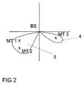
- a base station BS with directional selective Antennas use beam forming to produce directional radiation characteristics 4, 5, which are used for data targeted in the direction of the current whereabouts of To transfer subscriber terminals MT1, MT2, MT3.
- Such methods are, for example, from the state cited at the beginning known in the art and are weighted appropriately of individual signals of an antenna from several individual antenna elements realized.
- the base stations BS1, BS2 in 1 have a simplified beam forming unit (BF-Unit) designated facility, which by means of special Beam Forming Algorithms the optimal radiation characteristics the directional antennas of the base stations Determine BS1, BS2.
- BF-Unit beam forming unit
- Beam Forming Algorithms the optimal radiation characteristics the directional antennas of the base stations Determine BS1, BS2.
- a directional Transmission can be particularly disruptive Transmission to the terminal MT on other existing communication connections in the mobile network, especially due to Interference can be minimized.
- base station BS1 that is currently on Terminal MT maintains a communication link over which Knowledge of the parameters used for beam forming has to optimally supply this device.
- the neighboring base station BS2 in one process step 2 the data transmitted in the upward direction UL of the terminal MT.
- the base station BS2 determines in the frame an evaluation by an appropriate institution - In Fig. 1 schematically as initiation and analysis Unit, I & A unit called - takes place, a radiation pattern for the directionally selective antennas of the base station BS2, with which a directionally selective communication link could be set up to the terminal MT. This happens, even before a communication link to the terminal MT actually is built up.
- the base station BS2 procures itself therefore even before the need to establish a connection the necessary knowledge to the terminal MT in order to a subsequent connection establishment directly one optimal directionally selective communication link to the To be able to establish the terminal MT.
- the here schematically as Initiation and Analysis Unit, I&A Unit designated facility can also be realized by several separate facilities be that functionally meet the needs of the evaluation of the received radio signals and one in the following described possible initiation of this evaluation become.
- the evaluation can be done, for example, by signaling 1a on the part of the base station originally supplying the terminal MT BS1 to the I&A unit, taking the signaling Information about an upcoming handover of the Terminal MT to the base station BS2, possibly also Position data of the terminal device MT as well as further helpful information contain. But it can also be an initiation by means of a signal 1b on the part of the terminal MT, controlled by a device of the terminal MT 1, which is shown schematically in FIG. 1 as initiation unit, I unit, was designated. This facility can also be within of the terminal MT by any suitable technical component can be realized, which can control such an initiation.
- the signaling of the terminal MT can, for example Information about a handover request from the end device Contain MT, e.g. on current measurements of reception conditions based on the location of the terminal device MT can.
- a signal on the part of the terminal MT can either special data sequences that are unique for this initiation can be used, or for example Data sequences used in the context of other signaling used, for example sequences from the random access procedures RACH of the cellular network. This can e.g. then provided when two-level random access in the mobile network Procedures are provided in which initial access is general starts with a short signaling sequence.
- the unit, I&A unit then identify the signaling received as an initiation of an evaluation and precisely not as the usual random access sequence within a random Access procedure.
- the base station BS2 even the necessary information from the signaling 1b gain an appropriate polar pattern to determine without further radio signals in the upward direction UL to evaluate the terminal MT.
- the signaling 1a or 1b is in the usual transmission paths in Mobile network from the base station BS1 or the terminal MT transmitted to the base station BS2. In Fig. 1 this transfer is only schematically by arrows between the corresponding Units shown.
- the base station BS2 can also be provided that controlled by suitable time signals 1c, which in the example 1 are generated in the base station BS2 itself, the base station BS2 at certain times or at regular intervals Time intervals the radio signals of the terminal MT evaluates.
- the base station ideally does not only the radio signals of a terminal MT, but also the Evaluate radio signals from other end devices that are within range of the radio signals.
- the result of the evaluation of the radio signals received by the Terminal MT through the base station BS2 can also be used as another Decision criterion for a handover of the terminal MT used from the base station BS1 to the base station BS2 because there are potential shadowing problems can be checked in this way.
Landscapes
- Engineering & Computer Science (AREA)
- Computer Networks & Wireless Communication (AREA)
- Signal Processing (AREA)
- Mobile Radio Communication Systems (AREA)
- Radio Transmission System (AREA)
Abstract
Description
- eine Einrichtung zur richtungsselektiven Auswertung von Funksignalen, welche von einem Endgerät ausgesandt wurden,
- eine Einrichtung zur Zuweisung von Übertragungskapazitäten zu dem Endgerät und
- adaptive Antennen zum Aufbau einer Kommunikationsverbindung zu dem Endgerät.
- Fig. 1:
- Schematische Darstellung der erfindungsgemäßen Verfahrensabläufe in einem Funk-Kommunikationssystem
- Fig. 2:
- Schematische Darstellung der richtungsselektiven Wirkung des Beam Forming
Claims (11)
- Verfahren zur Zuweisung von Übertragungskapazitäten zu einem Endgerät (MT) in einem Funk-Kommunikationssystem, wobei eine erste Sende-/Empfangseinrichtung (BS1) eine Kommunikationsverbindung zu dem Endgerät (MT) mit Hilfe von adaptiven Antennen unterhält,
dadurch gekennzeichnet, dass eine zweite Sende-/Empfangseinrichtung (BS2) eine richtungsselektive Auswertung von Funksignalen (2) durchführt, welche von dem Endgerät (MT) ausgesandt wurden, auf Basis dieser Auswertung eine Zuweisung von Übertragungskapazitäten zu dem Endgerät durchführt und mit Hilfe von adaptiven Antennen eine Kommunikationsverbindung (3) zu dem Endgerät (MT) aufbaut. - Verfahren nach Anspruch 1,
dadurch gekennzeichnet, dass die Zuweisung von Übertragungskapazitäten im Rahmen eines Handovers von der ersten Sende-/Empfangseinrichtung (BS1) zu der zweiten Sende-/Empfangseinrichtung (BS2) erfolgt. - Verfahren nach Anspruch 1 oder 2,
dadurch gekennzeichnet, dass die zweite Sende-/Empfangseinrichtung (BS2) mit Hilfe von adaptiven Antennen eine richtungsselektive Auswertung der Funksignale (2) durchführt, welche von dem Endgerät (MT) ausgesandt wurden. - Verfahren nach einem der Ansprüche 1 bis 3,
dadurch gekennzeichnet, dass die Auswertung der vom Endgerät (MT) ausgesandten Funksignale (2) durch eine Signalisierung (1a) seitens des Funk-Kommunikationssystems an die zweite Sende-/Empfangseinrichtung (BS2) initiiert wird. - Verfahren nach Anspruch 4,
dadurch gekennzeichnet, dass die Signalisierung (1a) Informationen über einen bevorstehenden Handover des Endgerätes (MT) zu der zweiten Sende-/Empfangseinrichtung (BS2) enthält. - Verfahren nach einem der Ansprüche 1 bis 3,
dadurch gekennzeichnet, dass die Auswertung der vom Endgerät (MT) ausgesandten Funksignale (3) durch eine Signalisierung (1b) seitens des Endgeräts (MT) an die zweite Sende-/Empfangseinrichtung (BS2) initiiert wird. - Verfahren nach Anspruch 6,
dadurch gekennzeichnet, dass die Signalisierung (1b) eine Handover-Anforderung des Endgerätes (MT) an die zweite Sende-/Empfangseinrichtung (BS2) enthält. - Verfahren nach Anspruch 6 oder 7,
dadurch gekennzeichnet, dass als Signalisierung (1b) eine für die Initiierung der Auswertung eindeutige Datensequenz verwendet wird. - Verfahren nach Anspruch 6 oder 7,
dadurch gekennzeichnet, dass als Signalisierung (1b) eine für einen Zugriff auf das Funk-Kommunikationssystem definierte Datensequenz verwendet wird. - Verfahren nach einem der Ansprüche 1 bis 3,
dadurch gekennzeichnet, dass die Auswertung der vom Endgerät (MT) ausgesandten Funksignale (2) durch eine Zeitinformation (1c) initiiert wird. - Basisstationssystem mit Einrichtungen zur Zuweisung von Übertragungskapazitäten zu einem Endgerät (MT), wobei zumindest eine erste Sende-/Empfangseinrichtung (BS1) adaptive Antennen aufweist,
dadurch gekennzeichnet, dass zumindest eine zweite Sende-/Empfangseinrichtung (BS2) folgendes aufweist:eine Einrichtung (I&A-Unit) zur richtungsselektiven Auswertung von Funksignalen (2), welche von einem Endgerät (MT) ausgesandt wurden,eine Einrichtung (BF-Unit) zur Zuweisung von Übertragungskapazitäten zu dem Endgerät (MT) undadaptive Antennen zum Aufbau einer Kommunikationsverbindung (3) zu dem Endgerät (MT).
Priority Applications (4)
| Application Number | Priority Date | Filing Date | Title |
|---|---|---|---|
| DE50101076T DE50101076D1 (de) | 2001-03-15 | 2001-03-15 | Zuweisung von Übertragungskapazitäten in einem Funk-Kommunikationssystem mit Hilfe von adaptiven Antennen |
| TR2003/02315T TR200302315T4 (tr) | 2001-03-15 | 2001-03-15 | Uyarlanabilir antenler yardımıyla bir telefon iletişim sistemindeki aktarma kapasitesinin tahsisi. |
| EP01106702A EP1241908B1 (de) | 2001-03-15 | 2001-03-15 | Zuweisung von Übertragungskapazitäten in einem Funk-Kommunikationssystem mit Hilfe von adaptiven Antennen |
| AT01106702T ATE255799T1 (de) | 2001-03-15 | 2001-03-15 | Zuweisung von übertragungskapazitäten in einem funk-kommunikationssystem mit hilfe von adaptiven antennen |
Applications Claiming Priority (1)
| Application Number | Priority Date | Filing Date | Title |
|---|---|---|---|
| EP01106702A EP1241908B1 (de) | 2001-03-15 | 2001-03-15 | Zuweisung von Übertragungskapazitäten in einem Funk-Kommunikationssystem mit Hilfe von adaptiven Antennen |
Publications (2)
| Publication Number | Publication Date |
|---|---|
| EP1241908A1 true EP1241908A1 (de) | 2002-09-18 |
| EP1241908B1 EP1241908B1 (de) | 2003-12-03 |
Family
ID=8176821
Family Applications (1)
| Application Number | Title | Priority Date | Filing Date |
|---|---|---|---|
| EP01106702A Expired - Lifetime EP1241908B1 (de) | 2001-03-15 | 2001-03-15 | Zuweisung von Übertragungskapazitäten in einem Funk-Kommunikationssystem mit Hilfe von adaptiven Antennen |
Country Status (4)
| Country | Link |
|---|---|
| EP (1) | EP1241908B1 (de) |
| AT (1) | ATE255799T1 (de) |
| DE (1) | DE50101076D1 (de) |
| TR (1) | TR200302315T4 (de) |
Cited By (1)
| Publication number | Priority date | Publication date | Assignee | Title |
|---|---|---|---|---|
| EP1641300A1 (de) * | 2004-09-23 | 2006-03-29 | Siemens Aktiengesellschaft | Verfahren zur Datenübertragung in einem Funk-Kommunikationssystem |
Citations (3)
| Publication number | Priority date | Publication date | Assignee | Title |
|---|---|---|---|---|
| WO1998039945A1 (en) * | 1997-03-05 | 1998-09-11 | Nokia Telecommunications Oy | A method for selecting a signal, and a cellular radio system |
| WO1999033304A1 (en) * | 1997-12-19 | 1999-07-01 | Telefonaktiebolaget Lm Ericsson (Publ) | Method and system for improving handoffs in cellular mobile radio systems |
| WO2000051368A2 (en) * | 1999-02-26 | 2000-08-31 | Telefonaktiebolaget Lm Ericsson (Publ) | Smart antenna beam assignment at mobile station hand-off |
-
2001
- 2001-03-15 EP EP01106702A patent/EP1241908B1/de not_active Expired - Lifetime
- 2001-03-15 DE DE50101076T patent/DE50101076D1/de not_active Expired - Fee Related
- 2001-03-15 AT AT01106702T patent/ATE255799T1/de not_active IP Right Cessation
- 2001-03-15 TR TR2003/02315T patent/TR200302315T4/xx unknown
Patent Citations (3)
| Publication number | Priority date | Publication date | Assignee | Title |
|---|---|---|---|---|
| WO1998039945A1 (en) * | 1997-03-05 | 1998-09-11 | Nokia Telecommunications Oy | A method for selecting a signal, and a cellular radio system |
| WO1999033304A1 (en) * | 1997-12-19 | 1999-07-01 | Telefonaktiebolaget Lm Ericsson (Publ) | Method and system for improving handoffs in cellular mobile radio systems |
| WO2000051368A2 (en) * | 1999-02-26 | 2000-08-31 | Telefonaktiebolaget Lm Ericsson (Publ) | Smart antenna beam assignment at mobile station hand-off |
Cited By (1)
| Publication number | Priority date | Publication date | Assignee | Title |
|---|---|---|---|---|
| EP1641300A1 (de) * | 2004-09-23 | 2006-03-29 | Siemens Aktiengesellschaft | Verfahren zur Datenübertragung in einem Funk-Kommunikationssystem |
Also Published As
| Publication number | Publication date |
|---|---|
| TR200302315T4 (tr) | 2004-02-23 |
| ATE255799T1 (de) | 2003-12-15 |
| DE50101076D1 (de) | 2004-01-15 |
| EP1241908B1 (de) | 2003-12-03 |
Similar Documents
| Publication | Publication Date | Title |
|---|---|---|
| DE60211609T2 (de) | Verfahren zur Leistungsregelung während des sanften Überreichens in einem drahtlosen Übertragungssystem | |
| DE60310467T2 (de) | Zellumschaltungsverfahren durch den Mobil initiiert in drahtlosen Kommunikationssystemen. | |
| DE3752127T2 (de) | Umlegeeinrichtung und Verfahren zur Interferenzverminderung für ein Funksystem | |
| DE60222779T2 (de) | Kommunikationsregelungsverfahren und Vorrichtung in einem Mobilfunksystem | |
| DE69735320T2 (de) | Sendeleistungssteuerung für die Abwärtsrichtung eines Mobilkommunikationssystems mit Site-Diversität | |
| DE602004002883T2 (de) | Verfahren zur Verbesserung der Kapazität eines Rückverbindungskanals in einem drahtlosen Netzwerk | |
| DE69900404T2 (de) | Verfahren und vorrichtung für gruppenanrufe in einem schnurlosen cdma-kommunikationssystem | |
| DE19882703B4 (de) | Verfahren und Einrichtung in einem Mobiltelekommunikationsnetz | |
| DE69909774T2 (de) | Sendenantennendiversity | |
| DE202005009138U1 (de) | Vorrichtung und System zur Nutzung von Smart-Antennen bei der Einrichtung eines Backhaul-Netzwerks | |
| WO2002095981A1 (de) | Verfahren zum steuern der strahlformung in einem mobilfunk-kommunikationssystem und basisstation dafür | |
| EP0830043A1 (de) | Basisstation und Verfahren zur Versorgung einer Zelle eines zellularen Mobilfunksystems | |
| DE19653122A1 (de) | Verfahren zur Sprachübertragung über eine Funkschnittstelle in einem digitalen Funk-Kommunikationssystem mit Mobilstationen und Basisstationen | |
| DE69925382T2 (de) | Verfahren und system zur steuerung von "hard" und "soft" handoff in funkkommunikationssystemen | |
| EP0983642B1 (de) | Verfahren und vorrichtung zur sendeleistungsregelung für verbindungen zwischen einer basisstation und mobilstationen eines funk-kommunikationssystems | |
| DE19843982B4 (de) | Verfahren und Basisstation zur Kanalzuweisung in einem Funk-Kommunikationssystem | |
| EP1241908B1 (de) | Zuweisung von Übertragungskapazitäten in einem Funk-Kommunikationssystem mit Hilfe von adaptiven Antennen | |
| EP1226666B1 (de) | Verfahren zur synchronisation einer signalübertragung in aufwärtsrichtung in einem funk-kommunikationssystem | |
| WO2004025780A1 (de) | Ansteuerung einer antennenordnung, deren umfeld in sektoren unterteilt ist | |
| DE69937849T2 (de) | Verfahren zur Kanalwandlung in einem digitalen Funkkommunikationssystem | |
| DE19813182B4 (de) | Verfahren und Anordnung zur Kanalzuweisung in einem Funk-Kommunikationssystem | |
| DE10112576C2 (de) | Verfahren zur Zuweisung von Übertragungskapazitäten in einem Funk-Kommunikationssystem mit Hilfe von adaptiven Antennen | |
| WO2005084045A1 (de) | Verfahren zur herstellung einer kommunikationsverbindung in einem kommunikationsnetz | |
| EP1080550B1 (de) | Verfahren und funkstation zur signalübertragung in einem funk-kommunikationssystem | |
| DE10245113A1 (de) | Vorbereitung einer Intersystem-Verbindungsweiterschaltung |
Legal Events
| Date | Code | Title | Description |
|---|---|---|---|
| PUAI | Public reference made under article 153(3) epc to a published international application that has entered the european phase |
Free format text: ORIGINAL CODE: 0009012 |
|
| AK | Designated contracting states |
Kind code of ref document: A1 Designated state(s): AT BE CH CY DE DK ES FI FR GB GR IE IT LI LU MC NL PT SE TR |
|
| AX | Request for extension of the european patent |
Free format text: AL;LT;LV;MK;RO;SI |
|
| 17P | Request for examination filed |
Effective date: 20021203 |
|
| 17Q | First examination report despatched |
Effective date: 20030110 |
|
| GRAH | Despatch of communication of intention to grant a patent |
Free format text: ORIGINAL CODE: EPIDOS IGRA |
|
| AKX | Designation fees paid |
Designated state(s): AT BE CH CY DE DK ES FI FR GB GR IE IT LI LU MC NL PT SE TR |
|
| GRAS | Grant fee paid |
Free format text: ORIGINAL CODE: EPIDOSNIGR3 |
|
| GRAA | (expected) grant |
Free format text: ORIGINAL CODE: 0009210 |
|
| AK | Designated contracting states |
Kind code of ref document: B1 Designated state(s): AT BE CH CY DE DK ES FI FR GB GR IE IT LI LU MC NL PT SE TR |
|
| PG25 | Lapsed in a contracting state [announced via postgrant information from national office to epo] |
Ref country code: IT Free format text: LAPSE BECAUSE OF FAILURE TO SUBMIT A TRANSLATION OF THE DESCRIPTION OR TO PAY THE FEE WITHIN THE PRESCRIBED TIME-LIMIT;WARNING: LAPSES OF ITALIAN PATENTS WITH EFFECTIVE DATE BEFORE 2007 MAY HAVE OCCURRED AT ANY TIME BEFORE 2007. THE CORRECT EFFECTIVE DATE MAY BE DIFFERENT FROM THE ONE RECORDED. Effective date: 20031203 Ref country code: IE Free format text: LAPSE BECAUSE OF FAILURE TO SUBMIT A TRANSLATION OF THE DESCRIPTION OR TO PAY THE FEE WITHIN THE PRESCRIBED TIME-LIMIT Effective date: 20031203 Ref country code: NL Free format text: LAPSE BECAUSE OF FAILURE TO SUBMIT A TRANSLATION OF THE DESCRIPTION OR TO PAY THE FEE WITHIN THE PRESCRIBED TIME-LIMIT Effective date: 20031203 Ref country code: CY Free format text: LAPSE BECAUSE OF FAILURE TO SUBMIT A TRANSLATION OF THE DESCRIPTION OR TO PAY THE FEE WITHIN THE PRESCRIBED TIME-LIMIT Effective date: 20031203 Ref country code: FI Free format text: LAPSE BECAUSE OF FAILURE TO SUBMIT A TRANSLATION OF THE DESCRIPTION OR TO PAY THE FEE WITHIN THE PRESCRIBED TIME-LIMIT Effective date: 20031203 |
|
| REG | Reference to a national code |
Ref country code: GB Ref legal event code: FG4D Free format text: NOT ENGLISH |
|
| REG | Reference to a national code |
Ref country code: CH Ref legal event code: EP |
|
| REG | Reference to a national code |
Ref country code: IE Ref legal event code: FG4D Free format text: GERMAN |
|
| REF | Corresponds to: |
Ref document number: 50101076 Country of ref document: DE Date of ref document: 20040115 Kind code of ref document: P |
|
| PG25 | Lapsed in a contracting state [announced via postgrant information from national office to epo] |
Ref country code: GR Free format text: LAPSE BECAUSE OF FAILURE TO SUBMIT A TRANSLATION OF THE DESCRIPTION OR TO PAY THE FEE WITHIN THE PRESCRIBED TIME-LIMIT Effective date: 20040303 Ref country code: DK Free format text: LAPSE BECAUSE OF FAILURE TO SUBMIT A TRANSLATION OF THE DESCRIPTION OR TO PAY THE FEE WITHIN THE PRESCRIBED TIME-LIMIT Effective date: 20040303 Ref country code: SE Free format text: LAPSE BECAUSE OF FAILURE TO SUBMIT A TRANSLATION OF THE DESCRIPTION OR TO PAY THE FEE WITHIN THE PRESCRIBED TIME-LIMIT Effective date: 20040303 |
|
| PG25 | Lapsed in a contracting state [announced via postgrant information from national office to epo] |
Ref country code: ES Free format text: LAPSE BECAUSE OF FAILURE TO SUBMIT A TRANSLATION OF THE DESCRIPTION OR TO PAY THE FEE WITHIN THE PRESCRIBED TIME-LIMIT Effective date: 20040314 |
|
| PG25 | Lapsed in a contracting state [announced via postgrant information from national office to epo] |
Ref country code: LU Free format text: LAPSE BECAUSE OF NON-PAYMENT OF DUE FEES Effective date: 20040315 Ref country code: AT Free format text: LAPSE BECAUSE OF NON-PAYMENT OF DUE FEES Effective date: 20040315 |
|
| GBT | Gb: translation of ep patent filed (gb section 77(6)(a)/1977) |
Effective date: 20040303 |
|
| PG25 | Lapsed in a contracting state [announced via postgrant information from national office to epo] |
Ref country code: BE Free format text: LAPSE BECAUSE OF NON-PAYMENT OF DUE FEES Effective date: 20040331 Ref country code: MC Free format text: LAPSE BECAUSE OF NON-PAYMENT OF DUE FEES Effective date: 20040331 |
|
| NLV1 | Nl: lapsed or annulled due to failure to fulfill the requirements of art. 29p and 29m of the patents act | ||
| REG | Reference to a national code |
Ref country code: IE Ref legal event code: FD4D |
|
| ET | Fr: translation filed | ||
| BERE | Be: lapsed |
Owner name: SIEMENS A.G. Effective date: 20040331 |
|
| PG25 | Lapsed in a contracting state [announced via postgrant information from national office to epo] |
Ref country code: DE Free format text: LAPSE BECAUSE OF NON-PAYMENT OF DUE FEES Effective date: 20041001 |
|
| PLBE | No opposition filed within time limit |
Free format text: ORIGINAL CODE: 0009261 |
|
| STAA | Information on the status of an ep patent application or granted ep patent |
Free format text: STATUS: NO OPPOSITION FILED WITHIN TIME LIMIT |
|
| 26N | No opposition filed |
Effective date: 20040906 |
|
| PG25 | Lapsed in a contracting state [announced via postgrant information from national office to epo] |
Ref country code: LI Free format text: LAPSE BECAUSE OF NON-PAYMENT OF DUE FEES Effective date: 20050331 Ref country code: CH Free format text: LAPSE BECAUSE OF NON-PAYMENT OF DUE FEES Effective date: 20050331 |
|
| REG | Reference to a national code |
Ref country code: CH Ref legal event code: PL |
|
| PG25 | Lapsed in a contracting state [announced via postgrant information from national office to epo] |
Ref country code: PT Free format text: LAPSE BECAUSE OF NON-PAYMENT OF DUE FEES Effective date: 20040503 |
|
| PGFP | Annual fee paid to national office [announced via postgrant information from national office to epo] |
Ref country code: GB Payment date: 20080320 Year of fee payment: 8 |
|
| REG | Reference to a national code |
Ref country code: FR Ref legal event code: TP |
|
| REG | Reference to a national code |
Ref country code: GB Ref legal event code: 732E Free format text: REGISTERED BETWEEN 20090205 AND 20090211 |
|
| GBPC | Gb: european patent ceased through non-payment of renewal fee |
Effective date: 20090315 |
|
| PG25 | Lapsed in a contracting state [announced via postgrant information from national office to epo] |
Ref country code: GB Free format text: LAPSE BECAUSE OF NON-PAYMENT OF DUE FEES Effective date: 20090315 |
|
| PGFP | Annual fee paid to national office [announced via postgrant information from national office to epo] |
Ref country code: TR Payment date: 20140304 Year of fee payment: 14 Ref country code: FR Payment date: 20140319 Year of fee payment: 14 |
|
| REG | Reference to a national code |
Ref country code: FR Ref legal event code: CD Owner name: NOKIA SOLUTIONS AND NETWORKS GMBH & CO.KG, DE Effective date: 20150211 |
|
| REG | Reference to a national code |
Ref country code: FR Ref legal event code: ST Effective date: 20151130 |
|
| PG25 | Lapsed in a contracting state [announced via postgrant information from national office to epo] |
Ref country code: FR Free format text: LAPSE BECAUSE OF NON-PAYMENT OF DUE FEES Effective date: 20150331 |
|
| PG25 | Lapsed in a contracting state [announced via postgrant information from national office to epo] |
Ref country code: TR Free format text: LAPSE BECAUSE OF NON-PAYMENT OF DUE FEES Effective date: 20150315 |