EP1243172A2 - Dispositif de retardement du matériel d'un système de distribution pneumatique - Google Patents
Dispositif de retardement du matériel d'un système de distribution pneumatique Download PDFInfo
- Publication number
- EP1243172A2 EP1243172A2 EP02005833A EP02005833A EP1243172A2 EP 1243172 A2 EP1243172 A2 EP 1243172A2 EP 02005833 A EP02005833 A EP 02005833A EP 02005833 A EP02005833 A EP 02005833A EP 1243172 A2 EP1243172 A2 EP 1243172A2
- Authority
- EP
- European Patent Office
- Prior art keywords
- outlet
- air
- delay device
- inlet
- opening
- Prior art date
- Legal status (The legal status is an assumption and is not a legal conclusion. Google has not performed a legal analysis and makes no representation as to the accuracy of the status listed.)
- Withdrawn
Links
Images

Classifications
-
- A—HUMAN NECESSITIES
- A01—AGRICULTURE; FORESTRY; ANIMAL HUSBANDRY; HUNTING; TRAPPING; FISHING
- A01C—PLANTING; SOWING; FERTILISING
- A01C7/00—Sowing
- A01C7/08—Broadcast seeders; Seeders depositing seeds in rows
- A01C7/081—Seeders depositing seeds in rows using pneumatic means
- A01C7/082—Ducts, distribution pipes or details thereof for pneumatic seeders
-
- A—HUMAN NECESSITIES
- A01—AGRICULTURE; FORESTRY; ANIMAL HUSBANDRY; HUNTING; TRAPPING; FISHING
- A01C—PLANTING; SOWING; FERTILISING
- A01C7/00—Sowing
- A01C7/04—Single-grain seeders with or without suction devices
- A01C7/042—Single-grain seeders with or without suction devices using pneumatic means
-
- A—HUMAN NECESSITIES
- A01—AGRICULTURE; FORESTRY; ANIMAL HUSBANDRY; HUNTING; TRAPPING; FISHING
- A01C—PLANTING; SOWING; FERTILISING
- A01C7/00—Sowing
- A01C7/20—Parts of seeders for conducting and depositing seed
- A01C7/206—Seed pipes
Definitions
- the invention relates to a material delay device for Reduction of material and air speed in one pneumatic distribution system that is upstream of an outlet of the pneumatic distribution system is arranged by the Air-borne material is deposited in a furrow in the ground.
- Furrow opener materials for planting equipment, seeders and other similar types of agricultural equipment is used in Generally relieved that air through a line is guided and the materials from the air flow to the discharge into a furrow created by the furrow opener.
- the materials are used at high speeds in the one transported relatively high volume air flow and often they jump out of the furrow or become out of the furrow blown out, especially when the air is out of the furrow is expelled.
- Seed that jumps up, but in the Furrow remains, is not placed at the correct distance, and the seed that jumps out of the furrow or not close placed in the bottom of the furrow, does not grow or germinate correct and does not lead to the development of healthy plants. Fertilizer or seed treatment that is placed incorrectly are ineffective in plant nutrition or in seed protection.
- Seed braking devices to slow down the seed before Dropping in the furrow usually involve that seed hits a mechanical device, but crashes the bump often damages the seed or otherwise and exposes the establishment of considerable wear. Ridges or steps that are somewhere in the path of the seed located, can damage the seeds and wear the Device. Any narrowing of the path in the air system can result in flow restrictions and wear areas have blockages from large seeds or Impurities are not uncommon. If the continue Air is not pushed out of the stream, the seeds can accelerated again after an initial slowdown and such acceleration can result in that the seed is blown out of the furrow or out you jump out. Facilities that control air speed decrease near the outlet of the line, slow it down Seeds often insufficient to jump the seed in to avoid the furrow.
- the object underlying the invention is seen in an improved material retarder for use in an agricultural pneumatic distribution system provide.
- a material delay device is proposed which is suitable, the seed or other materials in the pneumatic distribution system of an agricultural implement gently slow down and release air from the distribution system eject.
- the material delay device is in Essentially in the form of a cyclone and includes a hollow body with an inlet located in the Substantially tangent to a round, in particular cylindrical section opens.
- a material outlet opens in the axial direction of the body on a funnel-shaped Section that is radial in the downstream direction narrowed inside. An opening upstream of the fluid outlet expels air to the amount that comes out of the material outlet reduce air leakage.
- the material delay device slows down the material through the acting centrifugal force without breaking the seed or otherwise damaged. Ejecting a considerable amount Some of the air in the vicinity of the furrow opener bends Acceleration and a jump of the seed in the Furrow before.
- the material delay device is compact and can be easily and conveniently directly above the furrow opener to be ordered. Filters or sieves for opening to Air release is not required, causing causes of Wear and clogging have been eliminated.
- the axis of the inlet is downstream Angled towards the end of the body. That in the hollow body incoming material receives one directed towards the material outlet Speed component and is on a spiral track in Directed towards the downstream end.
- the axis of the hollow body is vertical oriented.
- the material outlet is then below of the inlet, while the inlet is oriented approximately horizontally is.
- the material retarder is preferred above the furrow opener near the outlet of the pneumatic distribution system arranged. The material falls then primarily through the action of gravity through the Material outlet down into the outlet of the distribution system and gets into the furrow in the ground. It is hardly going through remaining air is accelerated, which is not through the opening to the Releasing the air but flowing through the material outlet.
- the effective cross-sectional area of the opening through which the Air is expelled is expediently larger than that of the Material outlet. This accomplishes that at the opening the airflow has a lower resistance than am Material outlet.
- the cross-sectional area of the material outlet usually corresponds to that of the inlet.
- the opening for releasing air with a is preferred cylindrical extension, which is essentially connected with the round section is concentric and downstream of the Opens at a central point in the hollow body, so that the air with no loss of transported material escapes.
- the material rubs against the inner surface of the hollow body along.
- an exchangeable wear insert is in the hollow body that one cylindrical or round section in any other way having predetermined dimensions, positionable.
- the Body has an inlet and at an upstream end an outlet at a downstream end.
- the interchangeable wear insert includes a hollow, cylindrical element with an inner wear surface and an outer diameter that is approximately equal to predetermined dimensions, but is slightly smaller than that predetermined dimensions.
- the wear insert is in the hollow body can be used and includes an inlet receiving surface alignable with the inlet to from seeds carried in an air stream and others Planting material and the material around the inner Wear surface around and to the material outlet. It is a mounting structure for repair or replacement purposes for releasably attaching the wear insert in the Body provided.
- the inner wear surface can be covered with a particular spiral groove for guiding the material along the inner Wear surface.
- the attachment structure of the wear insert can be a Hold the cap with an opening for expelling air.
- the Opening can be an axially protruding into the hollow body Extension to air from a central part of the Eject material delay device.
- the present invention is on pneumatic seed drills usable, especially pneumatic precision seed drills and Drills. They have a storage container from which material to be spread and measured by the pneumatic Distribution system is pneumatically routed to a furrow. Upstream of the furrow reduces the invention Material delay device the speed of the Seeds and removes a significant portion of the Airflow.
- the opening is preferably for Release of air connected to a return line that the expelled air upstream of the material retarding device inlet again the pneumatic distribution system supplies.
- the air can be an inlet to the air supply or be fed to a storage container.
- FIG. 1 a device 10 for Material introduction into the ground is shown with a Device frame tube 12 for forward movement (F) over the floor connected is.
- the device 10 which as a drill opener for Grain is shown includes a tie rod or arm 18, that via a mounting structure 20 with the device frame tube 12 is pivotally connected and by one with the Support structure 20 and the lower rear end 26 of the Drawbar 18 connected spring assembly 24 down in Engagement with the ground is biased.
- An opener disc 30 is at end 26 offset from the forward direction Axis rotatably attached to a narrow material receiving Form furrow 34 in the ground.
- a depth dial 38 is on a depth adjustment assembly 40 near the leading one Side of the opening disc 30 arranged to the furrow depth control and the ground on one side of the furrow 34 to solidify.
- a coulter assembly 44 is nearby at the rear end 26 the trailing side of the opening disc 30 in the shadow of Opener disc 30 supported.
- the coulter assembly 44 includes an upright seed tube 46 extending from one location extends above the arm 18 where the seed tube 46 with the lower end of an upright line 48 which is connected Is part of a pneumatic distribution system 50. seeds and / or fertilizer or other materials totaling 52 are marked and by (not shown) storage facilities on the device 10 are measured by a Air flow entrained and by the pneumatic Distribution system 50 promoted to the coulter assembly 44 to be fed and placed in the furrow 34.
- the Material 52 flows through line 48 and seed tube 46 down and then exits at an outlet 60, which follows opens below and behind, from the seed tube 46 into the furrow 34 out.
- a seed press tab 64 extends from rear, lower end of outlet 60 down and back.
- a pressure wheel assembly 68 supported by the arm 18 behind the Opener disc 30 helps the seed firmly in the lower section position the furrow and contact the seed with enlarge the floor.
- a locking wheel 72 folds off the floor opposite furrow wall together and presses the ground against the material 52.
- the pneumatic manifold system 50 includes a material supply line 80, in the seed or seed and fertilizer or other similar material through an air volume from Storage location is promoted.
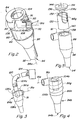
- a material delay device 84 essentially in the form of a chip separator, includes a hollow body 86 with a cylindrical section 88 with a cylinder axis 88a (FIG 2). Body 86 also includes an upstream end 90 one at the upstream end 90 substantially inlet opening tangentially into the cylindrical portion 88 91.
- a downstream end 92 with a material outlet 94 opens down in the axial direction and embraces a frusto-conical shaped portion 98 which from cylindrical section 88 to material outlet 94 (i.e. in the downstream direction) tapers radially inward.
- the Body 86 includes an opening 104 near the top of the cylindrical section 88 to upstream the air Material outlet 94 to release and the amount of the Reduce fluid outlet 94 leaving air.
- the opening 104 comprises a cylindrical extension 106, which in the Is essentially concentric with the section 88 and itself a central point 108 below the inlet 91 opens below so that the air without loss of desired Material 52 that is being transported escapes.
- the outer end of the inlet 91 is on a surface 110 slotted and has an inner diameter (D in Figure 2), which is approximately the same but slightly larger than the outer diameter of the material supply line 80.
- Die Material supply line 80 is inserted into inlet 91 and a clamp 112 becomes opposite the outer end surface 110 tightened to the material supply line 80 within the To hold inlet 91.
- Placing line 80 inside the inlet 91 avoids one step provided area that wears out and is a source of Seed damage could be.
- the lower end of the line 48 is attached to the upright seed tube 46 and the upper one End is positioned over the material outlet 94 and at the downstream end 92 of the material retarder 84 clamped.
- the inlet 91 has an axis 91a that is several angular degrees opposite an imaginary plane that is perpendicular to the axis 88a extends, is angled downwards, around which in the Material delay device 84 entering material 52 to give a slight axial component so that the Material 52 is directed to the material outlet 94.
- the angle between axis 91a and the plane is about five Degree. Seeds and other material entering the material retarder 84 occurs, will endeavor one spiral path along the inner surface of the cylindrical section 88 to follow. If the material 52 moves towards the material outlet 94, slows the through the centrifugal forces caused the material 52 to gently rub, without damaging material 52. Material 52 follows one spiral path along section 98 and emerges from the downstream end 92.
- the effective cross section is opening 104 larger than the area of the material outlet 94, so that the Air can be expelled effectively.
- material retarder 84 is shown about ninety percent of the air through opening 104 pushed out.
- the seeds and / or other material 52 fall under the Influence of gravity through line 48 and that Seed tube 46.
- the speed of material 52 significantly reduced and one caused by an air flow
- Material acceleration downstream of the material deceleration device 84 is essentially eliminated. Therefore is a Blowing out and jumping the material 52 out of the furrow 34 and jumping of material 52 in the groove 34 in Essentially avoided.
- the material retarder 84 is compact and becomes easy directly above the opener between lines 48 and 80 behind and essentially attached below the frame 12.
- one comprises Material delay device 84a an extension 106a, the protrudes from the upstream end 90a and a return line 120 receives an ejection opening 104a a remote location 124 connects.
- the Place 124 a portion of the pneumatic distribution system 50 upstream of the inlet 91.
- the point 124 may, for example the inlet of an air supply fan 124 or a Material storage container or container at the storage depot of the device.
- the return line 120 can therefore advantageously used for recirculation the efficiency of the pneumatic manifold system 50 enlarge, as well as a substantially closed System to provide dust and loss problems avoid using finer materials in the atmosphere without Filters or the like are required.
- Another Modification 124 may be an outlet opening near or easily penetrating the floor is arranged to put dust and other fine materials on or into the ground.
- the bottom location is preferably from the area of the furrow where the seed at the time is deposited, offset to accelerate the seed or blowing seeds or dirt out of the furrow 34 to avoid.
- Material delay device 84b has an inlet 91b with a hollow body 86b, which has a groove 86g for guiding the material 52 to the material outlet 94b.
- the axis 91a of the inlet 91b is slightly angled toward outlet 94b to allow movement in Direction of groove 86g to generate that as essentially is shown spirally. Air is drawn through extension 106b ejected through outlet 104b.
- FIG. 5 is a replaceable wear insert 130 with one in inlet 91 Received opening 132 slidably within the hollow Body 86 recorded and compared to the body 86 in one conventionally indexed, such as with a Ridge and a matching groove so that the opening 132 is aligned with the inlet 91.
- a cap 134 with an air exhaust extension 106c (partially in FIG. 5 omitted to better the inside of the wear insert 130 to show) includes a snap ring 136 connected to a molded groove 138 in the top of body 86 fits to wear insert 130 within the Secure body 86 with a lower edge 140 of the Wear insert 130 on the tapered portion 98 ends. Air is expelled through extension 106c opens at 144 through cap 134.
- Grooves 86g can also be provided in the wear insert 130 to provide guidance of material 52 toward material outlet 94 support. Support in the illustrated embodiment the grooves 86g convey the material 52 on one spiral path to material outlet 94.
- the body 86 can be made using a variety conventional methods, including through a plastic injection molding process.
- the Wear insert 130 can be made from a wear resistant Plastic material or a corrosion-resistant metal, such as Stainless steel.
- the wear insert is preferably made of an ultra high polyethylene Molecular weight (UHWM-PE) or urethane.
Landscapes
- Life Sciences & Earth Sciences (AREA)
- Soil Sciences (AREA)
- Environmental Sciences (AREA)
- Sowing (AREA)
- Air Transport Of Granular Materials (AREA)
Applications Claiming Priority (2)
| Application Number | Priority Date | Filing Date | Title |
|---|---|---|---|
| US09/814,595 US20020144637A1 (en) | 2001-03-22 | 2001-03-22 | Material decelerator for an air delivery system |
| US814595 | 2001-03-22 |
Publications (2)
| Publication Number | Publication Date |
|---|---|
| EP1243172A2 true EP1243172A2 (fr) | 2002-09-25 |
| EP1243172A3 EP1243172A3 (fr) | 2003-03-26 |
Family
ID=25215511
Family Applications (1)
| Application Number | Title | Priority Date | Filing Date |
|---|---|---|---|
| EP02005833A Withdrawn EP1243172A3 (fr) | 2001-03-22 | 2002-03-14 | Dispositif de retardement du matériel d'un système de distribution pneumatique |
Country Status (4)
| Country | Link |
|---|---|
| US (1) | US20020144637A1 (fr) |
| EP (1) | EP1243172A3 (fr) |
| AU (1) | AU2463102A (fr) |
| CA (1) | CA2373664A1 (fr) |
Cited By (5)
| Publication number | Priority date | Publication date | Assignee | Title |
|---|---|---|---|---|
| CN103813706A (zh) * | 2011-06-09 | 2014-05-21 | 踏板企业有限公司 | 用于空气输送材料的减速装置 |
| EP2832200A1 (fr) | 2013-08-01 | 2015-02-04 | Horsch Maschinen GmbH | Procédé et dispositif de dosage de matériel granulaire |
| WO2018036801A1 (fr) * | 2016-08-25 | 2018-03-01 | Bayer Cropscience Ag | Semoir |
| IT201700048758A1 (it) * | 2017-05-05 | 2018-11-05 | Matermacc S P A | Gruppo distributore |
| WO2023282830A1 (fr) * | 2021-07-06 | 2023-01-12 | Väderstad Holding Ab | Outil agricole et procédé d'alimentation en matériau granulaire |
Families Citing this family (18)
| Publication number | Priority date | Publication date | Assignee | Title |
|---|---|---|---|---|
| DE10313180A1 (de) * | 2003-03-25 | 2004-10-07 | Amazonen-Werke H. Dreyer Gmbh & Co. Kg | Pneumatische Sämaschine, insbesondere Einzelkornsämaschine |
| WO2005117564A1 (fr) * | 2004-06-04 | 2005-12-15 | D Scott Nominees Pty Ltd | Unite de dispersion de semences |
| USD647542S1 (en) | 2009-09-11 | 2011-10-25 | Agco-Amity Jv, Llc | Seed brake |
| EP2827698B1 (fr) * | 2012-03-22 | 2016-03-09 | Bayer Intellectual Property GmbH | Machine d'ensemencement et procédé d'ensemencement |
| US20150181799A1 (en) * | 2012-07-26 | 2015-07-02 | One Pass Implements Inc. | Ground opener assembly with dual gauge control |
| US8997310B2 (en) | 2012-10-12 | 2015-04-07 | Electrolux Home Care Products, Inc. | Vacuum cleaner cyclone with helical cyclone expansion region |
| USD689658S1 (en) | 2012-12-12 | 2013-09-10 | Electrolux Home Care Products, Inc. | Exterior surface of a cyclone receptacle |
| US9072217B2 (en) | 2013-02-22 | 2015-07-07 | John M. Kapphahn | Vacuum planter exhaust filtration system |
| CA2924046C (fr) * | 2013-10-08 | 2021-11-16 | Syngenta Participations Ag | Appareil d'enlevement de particules de l'air d'echappement d'un semoir et procede d'utilisation associe |
| ITUB20152403A1 (it) * | 2015-07-22 | 2017-01-22 | Matermacc S P A | Dispositivo di distribuzione di fertilizzanti. |
| US10159192B2 (en) * | 2015-09-17 | 2018-12-25 | Cone Guard, Llc | Transition cone liner for a farm combine |
| US9877425B2 (en) * | 2015-10-01 | 2018-01-30 | Deere & Company | Seed boot and liner assembly |
| US10136575B2 (en) * | 2016-07-28 | 2018-11-27 | Agco Corporation | Product row banding assembly for air delivery machines |
| CA2982462C (fr) * | 2016-11-08 | 2022-11-22 | Tread Enterprises Ltd. | Mecanisme de deceleration destine a un materiau transporte par un dispositif pneumatique |
| CN106612775B (zh) * | 2017-01-11 | 2023-03-31 | 安徽农业大学 | 一种组合式种肥兼用气送装置 |
| US12419213B2 (en) | 2019-05-08 | 2025-09-23 | Precision Planting Llc | Aerodynamic and centrifugal seed orientation system for agricultural planters |
| CN117898083B (zh) | 2019-05-08 | 2025-12-05 | 精密种植有限责任公司 | 用于农业播种机的种子定向系统 |
| US12575482B2 (en) * | 2021-10-11 | 2026-03-17 | Precision Planting Llc | Seed accelerator |
Family Cites Families (4)
| Publication number | Priority date | Publication date | Assignee | Title |
|---|---|---|---|---|
| FR1229027A (fr) * | 1959-03-19 | 1960-09-02 | Dispositif répartiteur de graines pour semoir mécanique | |
| US4002266A (en) * | 1972-08-14 | 1977-01-11 | Massey-Ferguson Inc. | Seed decelerating device |
| DE3637530C1 (de) * | 1986-11-04 | 1988-03-31 | Karl-Heinz Paul | Verfahren und Vorrichtung zum Saeen von vereinzelten Samen in eine von einem Schar gezogene Furche |
| US5974988A (en) * | 1995-12-29 | 1999-11-02 | Case Corporation | Seed metering apparatus seed tube |
-
2001
- 2001-03-22 US US09/814,595 patent/US20020144637A1/en not_active Abandoned
-
2002
- 2002-02-27 CA CA002373664A patent/CA2373664A1/fr not_active Abandoned
- 2002-03-14 EP EP02005833A patent/EP1243172A3/fr not_active Withdrawn
- 2002-03-18 AU AU24631/02A patent/AU2463102A/en not_active Abandoned
Cited By (10)
| Publication number | Priority date | Publication date | Assignee | Title |
|---|---|---|---|---|
| CN103813706A (zh) * | 2011-06-09 | 2014-05-21 | 踏板企业有限公司 | 用于空气输送材料的减速装置 |
| EP2717669A4 (fr) * | 2011-06-09 | 2015-08-12 | Tread Entpr Ltd | Amortisseur de chute destiné à un matériau acheminé de façon pneumatique |
| AU2012267180B2 (en) * | 2011-06-09 | 2015-10-22 | Tread Enterprises Ltd. | Decelerating device for air conveyed material |
| CN103813706B (zh) * | 2011-06-09 | 2016-05-18 | 踏板企业有限公司 | 用于空气输送材料的减速装置 |
| EP2832200A1 (fr) | 2013-08-01 | 2015-02-04 | Horsch Maschinen GmbH | Procédé et dispositif de dosage de matériel granulaire |
| DE102013215186A1 (de) * | 2013-08-01 | 2015-02-05 | Horsch Maschinen Gmbh | Verfahren zur Dosierung von körnigem Gut und Dosiervorrichtung für körniges Gut |
| WO2018036801A1 (fr) * | 2016-08-25 | 2018-03-01 | Bayer Cropscience Ag | Semoir |
| IT201700048758A1 (it) * | 2017-05-05 | 2018-11-05 | Matermacc S P A | Gruppo distributore |
| WO2018203157A1 (fr) * | 2017-05-05 | 2018-11-08 | Matermacc S.P.A. | Ensemble distributeur |
| WO2023282830A1 (fr) * | 2021-07-06 | 2023-01-12 | Väderstad Holding Ab | Outil agricole et procédé d'alimentation en matériau granulaire |
Also Published As
| Publication number | Publication date |
|---|---|
| EP1243172A3 (fr) | 2003-03-26 |
| CA2373664A1 (fr) | 2002-09-22 |
| AU2463102A (en) | 2002-09-26 |
| US20020144637A1 (en) | 2002-10-10 |
Similar Documents
| Publication | Publication Date | Title |
|---|---|---|
| EP1243172A2 (fr) | Dispositif de retardement du matériel d'un système de distribution pneumatique | |
| EP2832200B1 (fr) | Procédé et dispositif de dosage de matériel granulaire | |
| EP3026998B1 (fr) | Procédé et dispositif de dosage de matériel granulaire | |
| DE69915210T2 (de) | Lager- und Sammelbehälter in pneumatischen Drillmaschinen | |
| DE2629278A1 (de) | Verfahren und vorrichtung zur streugutzufuhrregulierung an mit druckluft betriebenen streugutverteil- und dosiermaschinen, insbesondere saemaschinen | |
| EP3372064A1 (fr) | Tour de distribution d'une machine agricole, machine agricole et procédé de fonctionnement d'une telle machine agricole | |
| DE2552067A1 (de) | Saemaschine | |
| EP0732044B1 (fr) | Conduit pour machine agricole | |
| EP3335535B1 (fr) | Dispositif de transport de matériau granulaire à epandre sur une surface agricole avec une pression de singulation égale | |
| DE4419964C2 (de) | Saatgutleitung für eine pneumatische Verteilmaschine | |
| DE202012101029U1 (de) | Sämaschine | |
| EP3340765B1 (fr) | Dispositif de dosage pour matériel granulaire avec réservoir collecteur | |
| EP3745838B1 (fr) | Dispositif de séparation | |
| EP0427936B2 (fr) | Epandeur d'engrais centrifuge | |
| DE102015114146A1 (de) | Dosiervorrichtung für granulares Material mit pneumatischer Nachfüllung | |
| EP3704923B1 (fr) | Dispositif pour un semoir agricole, procédé de séparation des semences dans un dispositif pour un semoir agricole ainsi que semoir | |
| EP3108732B1 (fr) | Dispositif pour transporter granulaire sur une surface agricole avec pression de refoulement réduite | |
| EP3811752B1 (fr) | Machine d'épandage | |
| DE3909721C2 (fr) | ||
| EP0385091B1 (fr) | Epandeur centrifuge | |
| DE102005050199A1 (de) | Vorrichtung zum Bestäuben von Produkten, insbesondere Druckprodukten | |
| DE102022122898A1 (de) | Elektronische Vorrichtung zum Erfassen von granularem Material innerhalb einer landwirtschaftlichen Verteilmaschine | |
| DE467659C (de) | Vorrichtung zur Verteilung und Zerkleinerung von Mitteln zur Schaedlingsbekaempfung von Luftfahrzeugen aus | |
| EP3108734B1 (fr) | Dispositif de transport pneumatique ameliore de materiau granulaire a epandre sur une surface agricole | |
| DE102015114153A1 (de) | Dosiervorrichtung für granulares Material mit Abbremsmitteln |
Legal Events
| Date | Code | Title | Description |
|---|---|---|---|
| PUAI | Public reference made under article 153(3) epc to a published international application that has entered the european phase |
Free format text: ORIGINAL CODE: 0009012 |
|
| AK | Designated contracting states |
Kind code of ref document: A2 Designated state(s): AT BE CH CY DE DK ES FI FR GB GR IE IT LI LU MC NL PT SE TR |
|
| AX | Request for extension of the european patent |
Free format text: AL;LT;LV;MK;RO;SI |
|
| PUAL | Search report despatched |
Free format text: ORIGINAL CODE: 0009013 |
|
| AK | Designated contracting states |
Kind code of ref document: A3 Designated state(s): AT BE CH CY DE DK ES FI FR GB GR IE IT LI LU MC NL PT SE TR Designated state(s): AT BE CH CY DE DK ES FI FR GB GR IE IT LI LU MC NL PT SE TR |
|
| AX | Request for extension of the european patent |
Extension state: AL LT LV MK RO SI |
|
| RIC1 | Information provided on ipc code assigned before grant |
Ipc: 7A 01C 7/08 B Ipc: 7A 01C 7/20 B Ipc: 7A 01C 7/04 A |
|
| 17P | Request for examination filed |
Effective date: 20030926 |
|
| AKX | Designation fees paid |
Designated state(s): DE ES FR GB IT |
|
| 17Q | First examination report despatched |
Effective date: 20031201 |
|
| STAA | Information on the status of an ep patent application or granted ep patent |
Free format text: STATUS: THE APPLICATION IS DEEMED TO BE WITHDRAWN |
|
| 18D | Application deemed to be withdrawn |
Effective date: 20040414 |