EP1243196B1 - Regenschirm mit einer verbesserten Hauptschieberarretierung - Google Patents
Regenschirm mit einer verbesserten Hauptschieberarretierung Download PDFInfo
- Publication number
- EP1243196B1 EP1243196B1 EP01302576A EP01302576A EP1243196B1 EP 1243196 B1 EP1243196 B1 EP 1243196B1 EP 01302576 A EP01302576 A EP 01302576A EP 01302576 A EP01302576 A EP 01302576A EP 1243196 B1 EP1243196 B1 EP 1243196B1
- Authority
- EP
- European Patent Office
- Prior art keywords
- runner
- end portion
- stem
- canopy
- axis
- Prior art date
- Legal status (The legal status is an assumption and is not a legal conclusion. Google has not performed a legal analysis and makes no representation as to the accuracy of the status listed.)
- Expired - Lifetime
Links
Images




Classifications
-
- A—HUMAN NECESSITIES
- A45—HAND OR TRAVELLING ARTICLES
- A45B—WALKING STICKS; UMBRELLAS; LADIES' OR LIKE FANS
- A45B25/00—Details of umbrellas
- A45B25/06—Umbrella runners
- A45B25/08—Devices for fastening or locking
Definitions
- This invention relates to an umbrella, more particularly to an umbrella with an improved runner fastener which is provided on a stem without weakening the structural strength of the same.
- a conventional umbrella is shown to include an elongate stem 1 with an upper elongate hole 101 in which a spring-loaded stop 2 is provided.
- a runner 3 is sleeved slidably on the stem 1 to connect pivotally with a stretcher assembly (not shown) to support a rib assembly (not shown) which is mounted on an upper end of the stem 1.
- the runner 3 is movable along the stem 1 between an upper position for stretching the rib assembly and a lower position for collapsing the same. At the upper position, the runner 3 is retainingly supported by the stop 2.
- the stem 3 of the conventional umbrella should be made hollow to receive the spring-loaded stop 2, it was not contemplated to provide a solid structure for the stem. Due to this inherent limitation of the stem, which is a primary part of the umbrella in terms of strength, it is quite difficult to further improve the rigidity of the stem, and hence the durability of the umbrella.
- the object of the present invention is to provide an umbrella which can overcome the aforementioned problems commonly associated with the prior art.
- the umbrella includes an elongate stem which extends along an axis, and which has a first upper end portion, a first lower end portion, and a middle portion therebetween.
- a ferrule is fixed on the first upper end portion of the stem.
- a tubular member surrounds the first upper end portion of the stem about the axis, and includes a second upper end portion which is fixed to the ferrule, and a second lower end portion which extends downwardly from the second upper end portion, and which is formed with a retaining slot that extends in a radial direction radial to the axis.
- a canopy is mounted on the first upper end portion of the stem.
- a rib assembly is disposed at an underside of the canopy to support the canopy in a spread-out position and in a collapsed position.
- a tubular runner is sleeved slidably on the stem, and has third upper and lower end portions respectively proximate and distal to the ferrule, and an intermediate portion therebetween. The runner is movable between upper and lower positions respectively corresponding to the spread-out and collapsed positions of the canopy.
- a stretcher assembly is disposed to interconnect the intermediate portion of the runner and the rib assembly so as to stretch or retract the rib assembly to put the canopy in the spread-out or collapsed position when the runner is moved to the upper or lower position, respectively.
- the third upper end portion of the runner is formed with a through hole which is aligned with the retaining slot in a longitudinal direction parallel to the axis, and which extends therethrough in the radial direction.
- the third upper end portion of the runner can be brought to surround the tubular member and to have the through hole registering with the retaining slot when the runner is in the upper position.
- a lever member defines a fulcrum portion which is pivoted to the intermediate portion of the runner about a pivot axis transverse to the longitudinal direction, and has upper and lower segments which are disposed at two opposite ends of the fulcrum portion and which are opposite to each other in the longitudinal direction.
- the upper segment has an anchoring end portion which extends radially and inwardly of the third upper end portion of the runner through the through hole and which is of such a dimension so as to be received and retained in the retaining slot when the runner is in the upper position.
- a biasing member is disposed to bias the anchoring end portion radially and inwardly toward the stem.
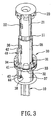
- the preferred embodiment of the umbrella according to the present invention is shown to comprise an elongate stem 10 which extends along an axis, and which has a first upper end portion 11, a first lower end portion, and a middle portion therebetween.
- a ferrule 20 is fixed on the first upper end portion 11 of the stem 10.
- a tubular member 21 is disposed to surround the first upper end portion 11 of the stem 10 about the axis, and includes a second upper end portion fixed to the ferrule 20, and a second lower end portion which extends downwardly from the second upper end portion, and which is formed with a retaining slot 22 that extends in a radial direction radial to the axis.
- a canopy 50 is mounted on the first upper end portion 11 of the stem 10.
- a rib assembly 60 is disposed at an underside of the canopy 50 to support the canopy 50 in a spread-out position and in a collapsed position.
- a tubular runner 30 is sleeved slidably on the stem 10, and has third upper and lower end portions 35,37 respectively proximate and distal to the ferrule 20, and an intermediate portion therebetween. The runner 30 is movable between upper and lower positions which respectively correspond to the spread-out and collapsed positions of the canopy 50.
- a stretcher assembly 70 is disposed to interconnect the intermediate portion of the runner 30 and the rib assembly 60 so as to stretch or retract the rib assembly 60 to put the canopy 50 in the spread-out or collapsed position when the runner 30 is moved to the upper or lower position, respectively.
- the third upper end portion 35 of the runner 30 is formed with a through hole 36 which is aligned with the retaining slot 22 in a longitudinal direction parallel to the axis, and which extends therethrough in the radial direction.
- the third upper end portion 35 of the runner 30 has an inner diameter sufficient so as to bring the same to surround the tubular member 21 and to have the through hole 36 registering with the retaining slot 22 when the runner 30 is in the upper position.
- the intermediate portion of the runner 30 is formed with a plurality of pivot slots 31 which are displaced angularly from each other about the axis for receiving a plurality of pivot ends of the stretcher assembly 70.
- a ring member 33 is disposed in to surround fixedly an annular groove 32 in the intermediate portion of the runner 30 such that the pivot ends of the stretcher assembly 70 are mounted pivotally thereon in a known manner.
- a recess 34 is formed on the intermediate portion of the runner 30 and extends in the longitudinal direction.
- a lever member 40 defines a fulcrum portion 41 which is pivoted to the intermediate portion of the runner 30 at the recess 34 about a pivot axis transverse to the longitudinal direction, and has upper and lower segments which are disposed at two opposite ends of the fulcrum portion 41 and which are opposite to each other in the longitudinal direction.
- the upper segment has an anchoring end portion 42 which extends radially and inwardly of the third upper end portion 35 of the runner 30 through the through hole 36.
- two cavities 38,43 are formed respectively in the third lower end portion 37 of the runner 30 and the lower segment of the lever member 40 and are opposite to each other in the radial direction such that a biasing member 44, such as a compression spring, is disposed between the cavities 38,43 so as to bias the lower segment outwardly and radially in order to turn the anchoring end portion 42 of the upper segment radially and inwardly toward the stem 10.
- a biasing member 44 such as a compression spring
Landscapes
- Walking Sticks, Umbrellas, And Fans (AREA)
Claims (3)
- Ein Schirm, aufweisend:Einen länglichen Schaft (10), der sich entlang einer Achse erstreckt und einen ersten oberen Endabschnitt (11), einen ersten unteren Endabschnitt und dazwischen einen mittleren Abschnitt hat;einen Endring (20), der an dem ersten oberen Endabschnitt des Schaftes (10) befestigt ist;eine Abschirmung (50), die an dem ersten oberen Endabschnitt (11) des Schaftes (10) montiert ist;eine Strebenanordnung (60), die an einer Unterseite der Abschirmung (50) angeordnet ist, um die Abschirmung (50) in einer aufgespreizten Position und in einer zusammengeklappten Position zu tragen;einen rohrförmigen Hauptschieber (30), der hülsenartig verschiebbar ist auf dem Schaft (10) und dritte obere bzw. untere Endabschnitte (35, 37) hat, die in der Nähe und distal zu dem Endring (20) sind, sowie einen Zwischenabschnitt dazwischen, wobei der Hauptschieber (30) bewegbar ist zwischen einer oberen bzw. unteren Position, entsprechend der aufgespreizten und zusammengeklappten Position der Abschirmung (50);eine Aufweitanordnung (70), die derart angeordnet ist, daß sie den Zwischenabschnitt des Hauptschiebers (30) und die Strebenanordnung (60) verbindet, um die Strebenanordnung (60) aufzuweiten oder zusammenzuziehen, um die Abschirmung (50) in die aufgespreizte oder zusammengeklappte Position zu bringen, wenn der Hauptschieber (30) in die obere oder untere Position jeweils bewegt wird,ein Hebelteil (40), das einen Drehabschnitt (41) definiert und verschwenkt wird zu dem Zwischenabschnitt des Hauptschiebers (30) um eine Schwenkachse, quer zu der Längsrichtung, sowie obere und untere Segmente hat, die an zwei gegenüberliegenden Enden des Drehabschnitts (41) angeordnet sind und in der Längsrichtung einander gegenüberliegen, wobei das obere Segment einen Verankerungsendabschnitt (42) hat, der radial und einwärts des dritten oberen Endabschnitts (35) desHauptschiebers (30) durch das Durchgangsloch (36) verläuft, undein Vorspannelement (44), das angeordnet ist, um den Verankerungsendabschnitt (42) radial und einwärts in Richtung des Schaftes (10) vorzuspannen, gekennzeichnet durch:ein rohrförmiges Teil (21), das den ersten oberen Endabschnitt (11) des Schaftes (10) um die Achse umgibt und einen zweiten oberen Endabschnitt aufweist, der an den Endring (20) befestigt ist, sowie einen zweiten unteren Endabschnitt, der von dem zweiten oberen Endabschnitt nach unten verläuft und der mit einem Halteschlitz (22) ausgebildet ist, der sich in einer radialen Richtung, radial zu der Achse erstreckt;die Ausbildung des dritten oberen Endabschnitts (35) des Hauptschiebers (30) mit einem Durchgangsloch (36), das mit dem Halteschlitz (22) in einer Längsrichtung, parallel zu der Achse, fluchtet und das sich dort hindurch in radialer Richtung erstreckt, wobei der dritte obere Endabschnitt (35) des Hauptschiebers (30) einen Innendurchmesser hat, der ausreicht, um so verbracht zu werden, daß er das rohrförmige Teil (21) umgibt, und das Durchgangsloch (36) übereinstimmt mit dem Halteschlitz (22), wenn der Hauptschieber (30) in der oberen Position ist; undeine Abmessung des Verankerungsendabschnittes (42) derart, daß er in dem Halteschlitz (22) aufnehmbar und haltbar ist, wenn der Hauptschieber (30) in der oberen Position ist.
- Schirm nach Anspruch 1, dadurch gekennzeichnet, daß das Vorspannelement (44) eine Kompressionsfeder ist, die zwischen dem dritten unteren Endabschnitt (37) des Hauptschiebers (30) und dem unteren Segment angeordnet ist und das in radialer Richtung verläuft, um das untere Segment nach außen und radial vorzuspannen, um das obere Segment nach innen und radial zu drehen.
- Schirm nach Anspruch 1, dadurch gekennzeichnet, daß der Hauptschieber (30) des weiteren aufweist: ein Ringteil (33), das den Zwischenabschnitt fest umgibt, wobei die Aufweitanordnung (70) mehrere Zapfenenden aufweist, die schwenkbar an dem Ringteil (33) montiert sind und die um die Achse winkelmäßig zueinander versetzt sind, wobei der Drehabschnitt (41) des Hebelteils (40) auf dem Ringteil (33) verschwenkbar ist.
Priority Applications (4)
| Application Number | Priority Date | Filing Date | Title |
|---|---|---|---|
| EP01302576A EP1243196B1 (de) | 2001-03-20 | 2001-03-20 | Regenschirm mit einer verbesserten Hauptschieberarretierung |
| DE60103494T DE60103494T2 (de) | 2001-03-20 | 2001-03-20 | Regenschirm mit einer verbesserten Hauptschieberarretierung |
| AT01302576T ATE267533T1 (de) | 2001-03-20 | 2001-03-20 | Regenschirm mit einer verbesserten hauptschieberarretierung |
| ES01302576T ES2221637T3 (es) | 2001-03-20 | 2001-03-20 | Paraguas con un dispositivo de fijacion de cursor mejorado. |
Applications Claiming Priority (1)
| Application Number | Priority Date | Filing Date | Title |
|---|---|---|---|
| EP01302576A EP1243196B1 (de) | 2001-03-20 | 2001-03-20 | Regenschirm mit einer verbesserten Hauptschieberarretierung |
Publications (2)
| Publication Number | Publication Date |
|---|---|
| EP1243196A1 EP1243196A1 (de) | 2002-09-25 |
| EP1243196B1 true EP1243196B1 (de) | 2004-05-26 |
Family
ID=8181810
Family Applications (1)
| Application Number | Title | Priority Date | Filing Date |
|---|---|---|---|
| EP01302576A Expired - Lifetime EP1243196B1 (de) | 2001-03-20 | 2001-03-20 | Regenschirm mit einer verbesserten Hauptschieberarretierung |
Country Status (4)
| Country | Link |
|---|---|
| EP (1) | EP1243196B1 (de) |
| AT (1) | ATE267533T1 (de) |
| DE (1) | DE60103494T2 (de) |
| ES (1) | ES2221637T3 (de) |
Families Citing this family (1)
| Publication number | Priority date | Publication date | Assignee | Title |
|---|---|---|---|---|
| RU2234226C1 (ru) * | 2003-01-23 | 2004-08-20 | Макс ВАНГ | Каркас зонта |
Family Cites Families (4)
| Publication number | Priority date | Publication date | Assignee | Title |
|---|---|---|---|---|
| GB931810A (en) * | 1961-05-04 | 1963-07-17 | T H Lawton & Co Manchester Ltd | Improvements in umbrellas, parasols and the like |
| US5253666A (en) * | 1992-09-10 | 1993-10-19 | Yung Shun Umbrella Co., Ltd. | Umbrella opening and closing device without use of spring latches |
| US5284171A (en) * | 1992-12-07 | 1994-02-08 | Liu Chin Hsiang | Sunshade opening and supporting device |
| US5964235A (en) * | 1998-03-11 | 1999-10-12 | Wang; Max | Umbrella with an improved runner fastener |
-
2001
- 2001-03-20 DE DE60103494T patent/DE60103494T2/de not_active Expired - Fee Related
- 2001-03-20 AT AT01302576T patent/ATE267533T1/de not_active IP Right Cessation
- 2001-03-20 ES ES01302576T patent/ES2221637T3/es not_active Expired - Lifetime
- 2001-03-20 EP EP01302576A patent/EP1243196B1/de not_active Expired - Lifetime
Also Published As
| Publication number | Publication date |
|---|---|
| ES2221637T3 (es) | 2005-01-01 |
| EP1243196A1 (de) | 2002-09-25 |
| DE60103494D1 (de) | 2004-07-01 |
| DE60103494T2 (de) | 2004-09-16 |
| ATE267533T1 (de) | 2004-06-15 |
Similar Documents
| Publication | Publication Date | Title |
|---|---|---|
| US5964235A (en) | Umbrella with an improved runner fastener | |
| US6311707B1 (en) | Umbrella | |
| US8381748B2 (en) | Walking and pickup stick | |
| EP3797844B1 (de) | Verriegelungsmechanismus für klappbare stock sowie klappbare stock | |
| US20050098200A1 (en) | Umbrella structure | |
| US7017936B2 (en) | Adjustable handle assembly for stroller or toy stroller | |
| US20020129843A1 (en) | Umbrella with buffering connection between ribs and stretchers | |
| EP0425071B1 (de) | Automatischer Schirm | |
| US5398709A (en) | Sunshade | |
| US7735911B2 (en) | Collapsible high chair for children | |
| US7588041B2 (en) | Control device for umbrella | |
| US6431191B1 (en) | Umbrella with an improved runner fastener | |
| EP1120057B1 (de) | Zusammenklappbarer Regenschirm | |
| EP1243196A1 (de) | Regenschirm mit einer verbesserten Hauptschieberarretierung | |
| US6173723B1 (en) | Structure of a skeleton for umbrellas | |
| US20080289668A1 (en) | Operation mechanism for umbrella | |
| KR101720424B1 (ko) | 길이조절이 가능한 스틱 | |
| US7255119B2 (en) | Slim safety runner and multiple-fold umbrella thereof | |
| US20060060234A1 (en) | Firm automatic multi-sectional collapsible umbrella structure | |
| EP1396205B1 (de) | Regenschirm | |
| US20030221714A1 (en) | Umbrella | |
| US5746440A (en) | Luggage carrier | |
| US7401616B2 (en) | Umbrella with a foldable stem | |
| JP3106536U (ja) | 堅固な多段折畳自動式傘の構造 | |
| KR100625111B1 (ko) | 접힘가능한 우산대를 포함한 우산 |
Legal Events
| Date | Code | Title | Description |
|---|---|---|---|
| PUAI | Public reference made under article 153(3) epc to a published international application that has entered the european phase |
Free format text: ORIGINAL CODE: 0009012 |
|
| AK | Designated contracting states |
Kind code of ref document: A1 Designated state(s): AT BE CH CY DE DK ES FI FR GB GR IE IT LI LU MC NL PT SE TR |
|
| AX | Request for extension of the european patent |
Free format text: AL;LT;LV;MK;RO;SI |
|
| 17P | Request for examination filed |
Effective date: 20021023 |
|
| AKX | Designation fees paid |
Designated state(s): AT BE CH CY DE DK ES FI FR GB GR IE IT LI LU MC NL PT SE TR |
|
| GRAP | Despatch of communication of intention to grant a patent |
Free format text: ORIGINAL CODE: EPIDOSNIGR1 |
|
| GRAS | Grant fee paid |
Free format text: ORIGINAL CODE: EPIDOSNIGR3 |
|
| GRAA | (expected) grant |
Free format text: ORIGINAL CODE: 0009210 |
|
| AK | Designated contracting states |
Kind code of ref document: B1 Designated state(s): AT BE CH CY DE DK ES FI FR GB GR IE IT LI LU MC NL PT SE TR |
|
| PG25 | Lapsed in a contracting state [announced via postgrant information from national office to epo] |
Ref country code: AT Free format text: LAPSE BECAUSE OF FAILURE TO SUBMIT A TRANSLATION OF THE DESCRIPTION OR TO PAY THE FEE WITHIN THE PRESCRIBED TIME-LIMIT Effective date: 20040526 Ref country code: TR Free format text: LAPSE BECAUSE OF FAILURE TO SUBMIT A TRANSLATION OF THE DESCRIPTION OR TO PAY THE FEE WITHIN THE PRESCRIBED TIME-LIMIT Effective date: 20040526 Ref country code: CH Free format text: LAPSE BECAUSE OF FAILURE TO SUBMIT A TRANSLATION OF THE DESCRIPTION OR TO PAY THE FEE WITHIN THE PRESCRIBED TIME-LIMIT Effective date: 20040526 Ref country code: NL Free format text: LAPSE BECAUSE OF FAILURE TO SUBMIT A TRANSLATION OF THE DESCRIPTION OR TO PAY THE FEE WITHIN THE PRESCRIBED TIME-LIMIT Effective date: 20040526 Ref country code: FI Free format text: LAPSE BECAUSE OF FAILURE TO SUBMIT A TRANSLATION OF THE DESCRIPTION OR TO PAY THE FEE WITHIN THE PRESCRIBED TIME-LIMIT Effective date: 20040526 Ref country code: BE Free format text: LAPSE BECAUSE OF FAILURE TO SUBMIT A TRANSLATION OF THE DESCRIPTION OR TO PAY THE FEE WITHIN THE PRESCRIBED TIME-LIMIT Effective date: 20040526 Ref country code: LI Free format text: LAPSE BECAUSE OF FAILURE TO SUBMIT A TRANSLATION OF THE DESCRIPTION OR TO PAY THE FEE WITHIN THE PRESCRIBED TIME-LIMIT Effective date: 20040526 Ref country code: IT Free format text: LAPSE BECAUSE OF FAILURE TO SUBMIT A TRANSLATION OF THE DESCRIPTION OR TO PAY THE FEE WITHIN THE PRESCRIBED TIME-LIMIT;WARNING: LAPSES OF ITALIAN PATENTS WITH EFFECTIVE DATE BEFORE 2007 MAY HAVE OCCURRED AT ANY TIME BEFORE 2007. THE CORRECT EFFECTIVE DATE MAY BE DIFFERENT FROM THE ONE RECORDED. Effective date: 20040526 |
|
| REG | Reference to a national code |
Ref country code: GB Ref legal event code: FG4D |
|
| REG | Reference to a national code |
Ref country code: CH Ref legal event code: EP |
|
| REG | Reference to a national code |
Ref country code: IE Ref legal event code: FG4D |
|
| REF | Corresponds to: |
Ref document number: 60103494 Country of ref document: DE Date of ref document: 20040701 Kind code of ref document: P |
|
| PG25 | Lapsed in a contracting state [announced via postgrant information from national office to epo] |
Ref country code: SE Free format text: LAPSE BECAUSE OF FAILURE TO SUBMIT A TRANSLATION OF THE DESCRIPTION OR TO PAY THE FEE WITHIN THE PRESCRIBED TIME-LIMIT Effective date: 20040826 Ref country code: GR Free format text: LAPSE BECAUSE OF FAILURE TO SUBMIT A TRANSLATION OF THE DESCRIPTION OR TO PAY THE FEE WITHIN THE PRESCRIBED TIME-LIMIT Effective date: 20040826 Ref country code: DK Free format text: LAPSE BECAUSE OF FAILURE TO SUBMIT A TRANSLATION OF THE DESCRIPTION OR TO PAY THE FEE WITHIN THE PRESCRIBED TIME-LIMIT Effective date: 20040826 |
|
| REG | Reference to a national code |
Ref country code: CH Ref legal event code: PL |
|
| NLV1 | Nl: lapsed or annulled due to failure to fulfill the requirements of art. 29p and 29m of the patents act | ||
| REG | Reference to a national code |
Ref country code: ES Ref legal event code: FG2A Ref document number: 2221637 Country of ref document: ES Kind code of ref document: T3 |
|
| ET | Fr: translation filed | ||
| PG25 | Lapsed in a contracting state [announced via postgrant information from national office to epo] |
Ref country code: CY Free format text: LAPSE BECAUSE OF FAILURE TO SUBMIT A TRANSLATION OF THE DESCRIPTION OR TO PAY THE FEE WITHIN THE PRESCRIBED TIME-LIMIT Effective date: 20050320 Ref country code: LU Free format text: LAPSE BECAUSE OF NON-PAYMENT OF DUE FEES Effective date: 20050320 |
|
| PG25 | Lapsed in a contracting state [announced via postgrant information from national office to epo] |
Ref country code: IE Free format text: LAPSE BECAUSE OF NON-PAYMENT OF DUE FEES Effective date: 20050321 |
|
| PG25 | Lapsed in a contracting state [announced via postgrant information from national office to epo] |
Ref country code: MC Free format text: LAPSE BECAUSE OF NON-PAYMENT OF DUE FEES Effective date: 20050331 |
|
| PLBE | No opposition filed within time limit |
Free format text: ORIGINAL CODE: 0009261 |
|
| STAA | Information on the status of an ep patent application or granted ep patent |
Free format text: STATUS: NO OPPOSITION FILED WITHIN TIME LIMIT |
|
| 26N | No opposition filed |
Effective date: 20050301 |
|
| REG | Reference to a national code |
Ref country code: IE Ref legal event code: MM4A |
|
| PG25 | Lapsed in a contracting state [announced via postgrant information from national office to epo] |
Ref country code: PT Free format text: LAPSE BECAUSE OF NON-PAYMENT OF DUE FEES Effective date: 20041026 |
|
| PGFP | Annual fee paid to national office [announced via postgrant information from national office to epo] |
Ref country code: GB Payment date: 20090318 Year of fee payment: 9 |
|
| PGFP | Annual fee paid to national office [announced via postgrant information from national office to epo] |
Ref country code: ES Payment date: 20090428 Year of fee payment: 9 |
|
| PGFP | Annual fee paid to national office [announced via postgrant information from national office to epo] |
Ref country code: DE Payment date: 20090313 Year of fee payment: 9 |
|
| PGFP | Annual fee paid to national office [announced via postgrant information from national office to epo] |
Ref country code: FR Payment date: 20090316 Year of fee payment: 9 |
|
| GBPC | Gb: european patent ceased through non-payment of renewal fee |
Effective date: 20100320 |
|
| REG | Reference to a national code |
Ref country code: FR Ref legal event code: ST Effective date: 20101130 |
|
| PG25 | Lapsed in a contracting state [announced via postgrant information from national office to epo] |
Ref country code: FR Free format text: LAPSE BECAUSE OF NON-PAYMENT OF DUE FEES Effective date: 20100331 |
|
| PG25 | Lapsed in a contracting state [announced via postgrant information from national office to epo] |
Ref country code: DE Free format text: LAPSE BECAUSE OF NON-PAYMENT OF DUE FEES Effective date: 20101001 |
|
| PG25 | Lapsed in a contracting state [announced via postgrant information from national office to epo] |
Ref country code: GB Free format text: LAPSE BECAUSE OF NON-PAYMENT OF DUE FEES Effective date: 20100320 |
|
| REG | Reference to a national code |
Ref country code: ES Ref legal event code: FD2A Effective date: 20110415 |
|
| PG25 | Lapsed in a contracting state [announced via postgrant information from national office to epo] |
Ref country code: ES Free format text: LAPSE BECAUSE OF NON-PAYMENT OF DUE FEES Effective date: 20110404 |
|
| PG25 | Lapsed in a contracting state [announced via postgrant information from national office to epo] |
Ref country code: ES Free format text: LAPSE BECAUSE OF NON-PAYMENT OF DUE FEES Effective date: 20100321 |