EP1243203B1 - Système de fixation pour glissières - Google Patents
Système de fixation pour glissières Download PDFInfo
- Publication number
- EP1243203B1 EP1243203B1 EP02004591A EP02004591A EP1243203B1 EP 1243203 B1 EP1243203 B1 EP 1243203B1 EP 02004591 A EP02004591 A EP 02004591A EP 02004591 A EP02004591 A EP 02004591A EP 1243203 B1 EP1243203 B1 EP 1243203B1
- Authority
- EP
- European Patent Office
- Prior art keywords
- rail
- mounting system
- fixing
- rail mounting
- hook
- Prior art date
- Legal status (The legal status is an assumption and is not a legal conclusion. Google has not performed a legal analysis and makes no representation as to the accuracy of the status listed.)
- Expired - Lifetime
Links
- 230000015572 biosynthetic process Effects 0.000 description 1
- 230000006835 compression Effects 0.000 description 1
- 238000007906 compression Methods 0.000 description 1
- 238000006073 displacement reaction Methods 0.000 description 1
- 238000000034 method Methods 0.000 description 1
Images




Classifications
-
- A—HUMAN NECESSITIES
- A47—FURNITURE; DOMESTIC ARTICLES OR APPLIANCES; COFFEE MILLS; SPICE MILLS; SUCTION CLEANERS IN GENERAL
- A47B—TABLES; DESKS; OFFICE FURNITURE; CABINETS; DRAWERS; GENERAL DETAILS OF FURNITURE
- A47B88/00—Drawers for tables, cabinets or like furniture; Guides for drawers
- A47B88/40—Sliding drawers; Slides or guides therefor
- A47B88/423—Fastening devices for slides or guides
- A47B88/43—Fastening devices for slides or guides at cabinet side
Definitions
- the present invention relates to a rail mounting system comprising a rail member and at least one fastener releasably mountable to the rail member for securing the rail to a body or wall member, wherein at least the fastener or rail member is formed as a profile member having two leg portions, the leg portions of that member Include other elements in the assembled state.
- Such rail mounting systems are known, for example, for fastening drawers, slots or guide rails.
- the rails are generally used for the lateral guidance of drawers, electronic components or modules in cabinets or Gargutlinin in ovens.
- the rail element may be a complete rail with a guide groove for the wearer.
- telescopic guides are used with an outer rail, a center rail and, depending on the desired extension length and stability optionally one or more middle rails.
- the aforementioned rail element may for example be the outer rail of such a telescopic guide.
- outer rail a telescopic guide called the body or the wall facing, fixedly mounted rail element.
- the inner rail is that of the side wall of the drawer or another rail facing rail element. Outside rail, inner rail and optionally provided therebetween inner rails are usually mounted against each other via ball or roller bearings.
- the outer rail of a telescopic guide is usually formed as a profile part and in cross-section C-shaped.
- the attachment of telescopic guides on a body by means of screws, which are screwed from the inside through holes in the outer rail into the body.
- located on the outer rail threaded bolt, which are guided through holes in the body wall and secured at the back by means of nuts.
- the outer rail has tapped holes, and the rail is fastened by means of screws which are guided from the outside through holes in the body wall.
- Rail element and fastener are in this case in at least two different positions with respect to the longitudinal direction of the rail combined to different overall lengths.
- an outer rail of a telescopic guide which can be connected via a variably adjustable mounting bracket with the body or cabinet.
- the mounting bracket has a slot, and the telescopic rail is provided with a threaded hole.
- the two elements can be assembled in different positions, so that the length of the rail is at least limited adjustable.
- DE 197 10 023 C1 discloses a device for fixing a multi-part telescopic extension, the fixed telescopic rail with mounting rails, frame legs and the like of a control cabinet is connected, wherein the fixed telescopic rail of the telescopic extension is mounted in a receptacle of two successively arranged U-shaped part support rails, said the partial support rails in a U-shaped base rail axially limited adjustable and fixed in their adjusted longitudinal positions and wherein the telescopic extension with its fixed telescopic rail itself on the base rail and the two sub-rails composed variable-length mounting rail unit axially limited adjustable and fixed in the adjusted longitudinal position.
- the partial support rails are provided with bolts which extend through slots in the base rail, so that a longitudinal displacement of the partial support rails relative to the base rail is possible, until the bolts are fixed with appropriate nuts to the slots of the base rail.
- the telescopic extension has further bolts, which also extend through slots in the base rail and the partial support rails and are fixed there by means of nuts.
- the present invention is therefore an object of the invention to provide a rail of the type mentioned above, wherein fastener and rail element can be joined together with little expenditure of time.
- the enclosed element is the rail element, such. B. the outer rail of a telescopic guide.
- the profile of the fastener engages with its leg portions of the rail element, wherein the rail element comes to rest on the inner wall of the profile of the fastener. Since the minimum distance between the two leg portions of the fastener is at least partially smaller than the maximum transverse extent of the enclosed element perpendicular to its longitudinal axis, therefore, for mounting the fastener to the rail element either the leg portions of the fastener have to be slightly bent apart and / or slightly compressed the rail element ,
- the rail element is undercut in cross-section, so that theticiangebogene or compressed state must be taken only during the assembly process. In the assembled state then the leg sections can again - at least almost - take their original position.
- the two elements can be assembled without the need for tools.
- telescopic rails are made of very rigid material, so that rail element and fastener can be assembled in some applications only by exercising a significant force.
- the leg portions at least one, preferably at least two projections, which are preferably formed as Einpressonne, wherein the minimum distance between the two leg portions by the distance between a projection and the opposite leg portion or between on the two leg portions opposite projections of different leg portions is formed.
- This has the advantage that the leg sections no longer have to be bent along their entire length, but only in the region of the projections.
- the formation of the projections as Einpressept has also the advantage that the projections can be inexpensively integrated into the profile part, without additional projections must be welded.
- a holding element is provided which prevents a relative movement between the elements in the longitudinal direction of the rail when the fastening element and rail element are joined together. This ensures that the rail element can not slip out of the fastener in the longitudinal direction.
- This holding element is advantageously made of a hook-recess connection.
- the rail element has at least one recess and the at least one fastening element has a hook, wherein the hook can be hooked into the at least one recess or can be brought into engagement therewith.
- the fastener can be easily hooked into the rail element without the use of tools and then folded up against the rail element until the rail element engages in the fastener.
- the rail element has at least two, preferably a plurality of recesses spaced in the longitudinal direction of the rail element.
- the fastener can be hooked and secured in the longitudinal direction in different positions on the rail member, so that the same rail can be used in different cabinet and cabinet depths.
- the rail element is preferably a profile part, which advantageously has a C-shaped cross-section.
- the C-shaped cross section ensures that the rail element can also be used as an outer rail for a telescopic rail. It is understood that the cross section of the profile part does not have to be round, but advantageously has the C-shaped cross-section on a flat back portion.
- the fastener on a profile part which preferably has a U-shaped cross-section.
- the cross sections of the two formed as profile elements elements are coordinated so that the outer contour of the rail element at least partially coincides with the inner contour of the fastener.
- rail element and fastening element in the assembled state along an overlapping portion, preferably the length of the C-shaped profile of the fastening element, in planar contact. This ensures that the rail has a good grip in the assembled state.
- the hook of the fastening element is first hooked into a recess of the rail element in this embodiment. Then, the fastener is pivoted about an axis formed by the connection hook recess until the rail member is parallel to the fastener.
- two fastening elements are provided for fastening the rail to a wall element.
- the rail to two fasteners can be attached to the wall element, the rail is able to carry even larger loads, such as heavy drawers.
- the fasteners are designed so that the rail is not directly applied to the cabinet wall or the body, but is somewhat spaced from this.
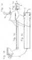
- the fastening element 1 has a U-shaped cross section with two leg sections 14. At the one end of the fastening element 1 designed as a profile part, as can be seen in the detail enlargement of FIG. 1d, a hook 2 intended.
- This hook 2 is formed by the fact that over the length of the fastener protruding tab is formed, which is angled at about 90 ° relative to the leg connecting the U-profile of the fastener, wherein the angled portion on its side facing away from the fastener again by 90 ° is angled in a direction substantially parallel to the leg connecting the U-profile.
- the tab has in cross section in approximately an S-shape.
- a mounting plate is provided, which is arranged laterally offset relative to the fastening element.
- the fastener is not directly, for example, on the inner wall of the body, but is somewhat spaced from this.
- the mounting plate has two threaded holes 5, with which this can be screwed for example to the inside of a carcass.
- four lateral recesses 6 are provided, which can also serve to fasten the fastener.
- the fastening element additionally has, in the region of the limbs of the U-shaped cross section, two opposing press-fits 3, which form projections on the inner surface of the legs. Due to the elastic properties of the material, the impressions 3 formed as projections can be moved by applying a force to the outside, that is to the left in FIG. 1e. The function of the projections 3 will be explained in more detail below.
- a further fastening element 7 is shown, which is connectable to the rail element and also has a mounting plate. Again, tapped holes 5 and recesses 6 are provided, by means of which the further fastening element 7 can be attached to the inner wall of a body.
- this fastener 7 has a staggered or cranked end, so that the mounting plate, although parallel to the rail element, but laterally offset thereto.
- the rail element 8 is shown.
- the rail element 8 is formed as a profile part and, as can be clearly seen in Figure 3b, a C-shaped cross-section. As can also be seen from FIG. 3b, however, the profile part 8 is not completely round, but the C-shaped cross section has a flat section in the area of the back 12.
- 12 recesses 9 are provided in the region of the back, which are formed such that the hook 2 of the illustrated in Figures 1a to 1e fastener 1 can engage in this.
- a plurality of mutually uniformly spaced recesses 9 is provided in the transverse direction.
- the rail element 8 has a maximum transverse extent of length e.
- FIG. 4a shows the state in which the fastening element 1 engages in the recess 9 of the rail element 8.
- the further fastening element 7 is provided which is connected to the rail element 8.
- Figure 4c shows in an enlarged detail the hooking position of the fastener 1 in the rail element 8. It can be clearly seen that the length d of the recesses 9 in the rail element is greater than the thickness b of the tab of the profile part 1. In addition, it can be seen that the cranked portion of the hook 2 has a length c which exceeds the length d of the recesses 9.
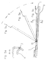
- the fastening element 1 with the hook 2 is first introduced into a recess 9 of the rail element 8. Thereafter, as can be seen in FIGS. 5 a to 5 c, the fastening element 1 is pivoted about the axis 13, which is formed approximately by one of the webs between the recesses 9. This can be done without effort until the position shown in Figure 5c is reached.
- FIG. 5 d which shows a section along the line A-A from FIG. 5 c
- the projections 3 of the fastening element 1 abut against the outer contour of the C-shaped profile part 8.
- the fastening element 1 can now be moved further downwards in the direction of the rail element 8 in FIG. 5d. Due to the ramp-like shape of the projections and / or the outer contour of the C-shaped profile part 8, the projection 3 can be pressed to the right in Figure 5d and slide the projection 3 at the point of maximum transverse extent of the rail element. Characterized in that the minimum distance between the two leg portions 14 and the projections 3 is smaller than the maximum transverse extent e of the rail member 8, the fastener 1 can be "clipped" to the rail member 8.
- the fastening element 1 has the position shown in Figures 6a to 6e.
- the projection 3 has the point of maximum transverse extent of the rail member passes so that it (at least partially) can emerge again from the U-leg and at the point 10 with the rail member 8 in Intervention occurs.
- the fastener 1 is securely locked to the rail element 8.
- the hook engages in the recess 9 in such a way that the fastening element 1 can not slip out of the recess 9 of the rail element in this position.
- the leg portions 14 of the fastener 1 include the rail member 8.
- the further fastener 7 advantageously bears in the same manner with the rail member 8, i. by means of a hook-recess connection, can be joined together as the fastening element 1 in the embodiment shown in the figures with the rail element eighth
- FIGS. 7a to 7e show a further embodiment of the rail mounting system according to the invention.
- the hook 2 is also formed here as a tab, wherein the tab has a widening at its end facing away from the fastener, so that the width g of the tab is slightly larger than the width h of the recess 9.
- Um Insert the hook 2 in the recess 9, the fastener 1 can not be used in the position shown in Figure 7b in the direction of arrow 9 in the recess of the rail element 8 become. Rather, as indicated by the round arrow, first the fastener 1 must be rotated relative to the rail member 8 by about 90 ° about the axis 14.
- the fastener 1 is then rotated back by about 90 ° about the axis 14 relative to the rail member 8. In this position, the thickened portions of the hook 2 engage behind the openings of the recess 9.
- the recess 9 is, as can be clearly seen in Figure 7e, here formed as a slot.
- the fastener 1 can be steplessly engaged with the rail member 8 in almost every position.
- the further assembly then takes place, as can be seen in Figures 7a and 7c, as in the previously described embodiment. It is understood that also in this embodiment, the minimum distance between the two leg portions of the fastener 1 is at least partially smaller than the maximum transverse extent of the rail member 8 perpendicular to its longitudinal axis.
- the inventive hook and clip system, the rail can be easily assembled (easy to use).
- the same rail can be used for different body or cabinet depths (variable usability).
- rail element 8 and fastener can be separated from each other only by removing the whole rail from the cabinet or body (high security).
Landscapes
- Drawers Of Furniture (AREA)
- Mutual Connection Of Rods And Tubes (AREA)
- Connection Of Plates (AREA)
Claims (13)
- Système de montage à glissière comportant un élément de glissière (8) et au moins un élément de fixation (1, 7) qui peut être monté de façon amovible sur l'élément de glissière (8) et qui est destiné à la fixation de l'élément de glissière (8) sur un corps ou un élément de paroi, l'élément de fixation (1, 7) ou l'élément de glissière (8) au moins étant conformé en pièce profilée comportant deux portions de branche (14), les portions de branche (14) de cet élément renfermant l'autre élément à l'état monté, caractérisé dans ce que la distance minimale (f) entre les deux portions de branche (14) est, au moins par portion, inférieure à la dimension transversale maximale (e) de l'élément renfermé, perpendiculairement à son axe longitudinal.
- Système de montage à glissière selon la revendication 1, caractérisé en ce que l'élément renfermé est l'élément de glissière (8).
- Système de montage à glissière selon la revendication 2, caractérisé en ce que les portions de branche (14) comportent au moins une saillie, avantageusement des saillies, qui sont conformées de préférence en renfoncements (3), la distance minimale (f) entre les deux portions de branche (14) étant formée par la distance entre une saillie (3) et la portion de branche opposée ou entre des saillies (3), opposées l'une à l'autre, de différentes portions de branche.
- Système de montage à glissière selon l'une des revendications 1 à 3, caractérisé en ce qu'il est prévu un élément de retenue (2, 9) qui empêche, lorsque l'élément de fixation (1, 7) et l'élément de glissière (8) sont assemblés, un mouvement relatif entre les éléments dans la direction longitudinale de l'élément de glissière.
- Système de montage à glissière selon la revendication 4, caractérisé en ce que l'élément de retenue (2, 9) est constitué par une liaison crochet (2)/évidement (9).
- Système de montage à glissière selon la revendication 5, caractérisé en ce que l'élément de glissière (8) comporte un évidement (9) ou plusieurs évidements, espacés dans la direction longitudinale de l'élément de glissière (8), et l'élément de fixation (1, 7) comporte un crochet (2), le crochet (2) pouvant être amené en engagement avec un évidement (9) ménagé dans l'élément de glissière (8).
- Système de montage à glissière selon l'une des revendications 1 à 6, caractérisé en ce que l'élément de glissière (8) est une pièce profilée qui a avantageusement une section en C.
- Système de montage à glissière selon l'une des revendications 1 à 7, caractérisé en ce que l'élément de fixation (1) comporte une pièce profilée qui a avantageusement une section en U.
- Système de montage à glissière selon l'une des revendications 1 à 8, caractérisé en ce que l'élément de glissière (8) et l'au moins un élément de fixation (1) sont en contact à plat le long d'une portion de recouvrement (11) à l'état assemblé.
- Système de montage à glissière selon l'une des revendications 1 à 9, caractérisé en ce qu'il est prévu deux éléments de fixation (1, 7) pour la fixation de l'élément de glissière (8) à un élément de paroi.
- Système de montage à glissière selon l'une des revendications 6 à 10, caractérisé en ce que le crochet (2) est formé par une attache qui fait saillie au-dessus de l'élément de fixation (1) au moins et qui est coudée au moins une fois, avantageusement deux fois, avantageusement de 90° environ.
- Système de montage à glissière selon la revendication 11, caractérisé en ce que l'attache (2) est coudée deux fois et la partie de l'attache, qui est opposée à l'élément de fixation, a une longueur c qui est supérieure à la largeur d des évidements (9).
- Système de montage à glissière selon l'une des revendications 1 à 12, caractérisé en ce que l'élément de glissière (8) est la glissière extérieure d'un guide télescopique comportant une glissière extérieure, une glissière intérieure et le cas échéant une ou plusieurs glissières intermédiaires, lesquelles sont montées de façon à pouvoir coulisser l'une par rapport à l'autre dans la direction longitudinale des glissières grâce des roulements à billes.
Applications Claiming Priority (2)
| Application Number | Priority Date | Filing Date | Title |
|---|---|---|---|
| DE20104933U DE20104933U1 (de) | 2001-03-21 | 2001-03-21 | Schienenmontagesystem |
| DE20104933U | 2001-03-21 |
Publications (3)
| Publication Number | Publication Date |
|---|---|
| EP1243203A2 EP1243203A2 (fr) | 2002-09-25 |
| EP1243203A3 EP1243203A3 (fr) | 2004-01-02 |
| EP1243203B1 true EP1243203B1 (fr) | 2006-08-09 |
Family
ID=7954642
Family Applications (1)
| Application Number | Title | Priority Date | Filing Date |
|---|---|---|---|
| EP02004591A Expired - Lifetime EP1243203B1 (fr) | 2001-03-21 | 2002-02-28 | Système de fixation pour glissières |
Country Status (2)
| Country | Link |
|---|---|
| EP (1) | EP1243203B1 (fr) |
| DE (2) | DE20104933U1 (fr) |
Families Citing this family (5)
| Publication number | Priority date | Publication date | Assignee | Title |
|---|---|---|---|---|
| DE102008048933A1 (de) * | 2008-09-25 | 2010-04-01 | Paul Hettich Gmbh & Co. Kg | Vorrichtung und Verfahren zur Montage einer Möbelauszugsführung für Auszugselemente |
| DE202009000241U1 (de) * | 2009-01-09 | 2010-05-27 | Hettich-Heinze Gmbh & Co. Kg | Schiene zum Aufhängen von Schränken |
| DE102011051138A1 (de) | 2011-06-17 | 2012-12-20 | Schock Metallwerk Gmbh | Auszugführung |
| DE102011051126A1 (de) | 2011-06-17 | 2012-12-20 | Schock Metallwerk Gmbh | Auszugführung und Auszugsvorrichtung |
| DE102011052524A1 (de) | 2011-08-09 | 2013-02-14 | Schock Metallwerk Gmbh | Auszugführung |
Family Cites Families (2)
| Publication number | Priority date | Publication date | Assignee | Title |
|---|---|---|---|---|
| DE29613357U1 (de) * | 1996-08-06 | 1997-12-04 | Mepla-Werke Lautenschläger GmbH & Co KG, 64354 Reinheim | Befestigungsanordnung von Führungsschienen von Ausziehführungen |
| DE19710023C1 (de) * | 1997-03-12 | 1998-04-30 | Loh Kg Rittal Werk | Vorrichtung zum Befestigen eines Teleskopauszuges in einem Schaltschrank |
-
2001
- 2001-03-21 DE DE20104933U patent/DE20104933U1/de not_active Expired - Lifetime
-
2002
- 2002-02-28 EP EP02004591A patent/EP1243203B1/fr not_active Expired - Lifetime
- 2002-02-28 DE DE50207757T patent/DE50207757D1/de not_active Expired - Lifetime
Also Published As
| Publication number | Publication date |
|---|---|
| EP1243203A3 (fr) | 2004-01-02 |
| DE20104933U1 (de) | 2001-09-20 |
| EP1243203A2 (fr) | 2002-09-25 |
| DE50207757D1 (de) | 2006-09-21 |
Similar Documents
| Publication | Publication Date | Title |
|---|---|---|
| DE2618442C2 (de) | Stütze für ein Geländer oder dergleichen | |
| EP2410190B1 (fr) | Dispositif de fixation d'un objet à un élément présentant une ouverture aux bords marqués | |
| DE4210456C2 (de) | Querverbindung für Profilstäbe mittels Zuggliedern | |
| EP0761130A2 (fr) | Ferrure de fixation pour panneaux frontaux de tiroir | |
| DE202010013011U1 (de) | Befestigungsanordnung für die Montage von Beschlagteilen | |
| EP0389954A2 (fr) | Dispositif pour guider et tenir un circuit imprimé | |
| EP1243203B1 (fr) | Système de fixation pour glissières | |
| DE102010004771B3 (de) | Türband für Aluminiumtüren | |
| EP2869417B1 (fr) | Dispositif de liaison de sections de conduit de câble et conduit de câble | |
| DE2923903C2 (fr) | ||
| EP3071896A1 (fr) | Dispositif de retenue pour boîtier et procédé de montage du boîtier à l'aide du dispositif de retenue | |
| DE19806922C1 (de) | Querverbinder für mit hinterschnittenen Längsnuten versehene stranggezogene Hohlprofilstäbe | |
| EP2783919B1 (fr) | Dispositif de fixation d'un coffre de toit | |
| EP0673094B1 (fr) | Dispositif angulaire de raccord pour structures de support utilisées dans des systèmes de distribution | |
| EP1873340B1 (fr) | Installation de porte | |
| EP3945936B1 (fr) | Dispositif de chargement ou d'éjection | |
| DE10042040C2 (de) | Vorrichtung zum Befestigen von Haltekörpern | |
| EP2803533B1 (fr) | Dispositif destiné à agencer une barre présentant un canal longitudinal sur un support | |
| DE19817427A1 (de) | Klemmverbinder | |
| AT528657B1 (de) | Ausziehführung, Möbelelement und Möbel | |
| DE10117794A1 (de) | Tischplattenverriegelung | |
| DE102018208501A1 (de) | Vorrichtung zur Fixierung von länglichen Gegenständen | |
| DE102005045039B3 (de) | Führungseinrichtungen | |
| EP1071859B1 (fr) | Dispositif de fermeture pour fenetres et portes a battants | |
| DE202024101607U1 (de) | Verbindungseinrichtung zur Verbindung einer Teleskopschiene eines Teleskopbeschlags mit einem Zugmittel, Teleskopbeschlag und Tisch mit einem Teleskopbeschlag |
Legal Events
| Date | Code | Title | Description |
|---|---|---|---|
| PUAI | Public reference made under article 153(3) epc to a published international application that has entered the european phase |
Free format text: ORIGINAL CODE: 0009012 |
|
| AK | Designated contracting states |
Kind code of ref document: A2 Designated state(s): AT BE CH CY DE DK ES FI FR GB GR IE IT LI LU MC NL PT SE TR |
|
| AX | Request for extension of the european patent |
Free format text: AL;LT;LV;MK;RO;SI |
|
| PUAL | Search report despatched |
Free format text: ORIGINAL CODE: 0009013 |
|
| AK | Designated contracting states |
Kind code of ref document: A3 Designated state(s): AT BE CH CY DE DK ES FI FR GB GR IE IT LI LU MC NL PT SE TR |
|
| AX | Request for extension of the european patent |
Extension state: AL LT LV MK RO SI |
|
| 17P | Request for examination filed |
Effective date: 20040625 |
|
| AKX | Designation fees paid |
Designated state(s): DE |
|
| 17Q | First examination report despatched |
Effective date: 20050628 |
|
| GRAP | Despatch of communication of intention to grant a patent |
Free format text: ORIGINAL CODE: EPIDOSNIGR1 |
|
| GRAS | Grant fee paid |
Free format text: ORIGINAL CODE: EPIDOSNIGR3 |
|
| GRAA | (expected) grant |
Free format text: ORIGINAL CODE: 0009210 |
|
| AK | Designated contracting states |
Kind code of ref document: B1 Designated state(s): DE |
|
| REF | Corresponds to: |
Ref document number: 50207757 Country of ref document: DE Date of ref document: 20060921 Kind code of ref document: P |
|
| PLBE | No opposition filed within time limit |
Free format text: ORIGINAL CODE: 0009261 |
|
| STAA | Information on the status of an ep patent application or granted ep patent |
Free format text: STATUS: NO OPPOSITION FILED WITHIN TIME LIMIT |
|
| 26N | No opposition filed |
Effective date: 20070510 |
|
| REG | Reference to a national code |
Ref country code: DE Ref legal event code: R079 Ref document number: 50207757 Country of ref document: DE Free format text: PREVIOUS MAIN CLASS: A47B0088040000 Ipc: A47B0088400000 |
|
| PGFP | Annual fee paid to national office [announced via postgrant information from national office to epo] |
Ref country code: DE Payment date: 20190415 Year of fee payment: 18 |
|
| REG | Reference to a national code |
Ref country code: DE Ref legal event code: R119 Ref document number: 50207757 Country of ref document: DE |
|
| PG25 | Lapsed in a contracting state [announced via postgrant information from national office to epo] |
Ref country code: DE Free format text: LAPSE BECAUSE OF NON-PAYMENT OF DUE FEES Effective date: 20200901 |