EP1243206A2 - Meuble de couchage réglable et cadre pour un tel meuble - Google Patents
Meuble de couchage réglable et cadre pour un tel meuble Download PDFInfo
- Publication number
- EP1243206A2 EP1243206A2 EP02405153A EP02405153A EP1243206A2 EP 1243206 A2 EP1243206 A2 EP 1243206A2 EP 02405153 A EP02405153 A EP 02405153A EP 02405153 A EP02405153 A EP 02405153A EP 1243206 A2 EP1243206 A2 EP 1243206A2
- Authority
- EP
- European Patent Office
- Prior art keywords
- lying
- frame
- fastening means
- longitudinal
- lying surface
- Prior art date
- Legal status (The legal status is an assumption and is not a legal conclusion. Google has not performed a legal analysis and makes no representation as to the accuracy of the status listed.)
- Granted
Links
Images


Classifications
-
- A—HUMAN NECESSITIES
- A47—FURNITURE; DOMESTIC ARTICLES OR APPLIANCES; COFFEE MILLS; SPICE MILLS; SUCTION CLEANERS IN GENERAL
- A47C—CHAIRS; SOFAS; BEDS
- A47C20/00—Head-, foot- or like rests for beds, sofas or the like
- A47C20/08—Head-, foot- or like rests for beds, sofas or the like with means for adjusting two or more rests simultaneously
Definitions
- the present invention is in the field of furniture and relates to an adjustable couch and a frame for one such couch according to the generic terms of the independent Claims.
- Lying between a lying position and a Sitting position are adjustable, being between these two Extreme positions can still be provided intermediate positions are known. They have a frame and a Lying surface on, which in the longitudinal direction in several segments is divided, with two neighboring ones Lying surface segments are hinged together.
- a sprocket attached to the frame, in which supports connected to the lying surface segments intervention.
- This construction has the disadvantage that the Lying area is necessarily higher than the frame. This is aesthetically unsatisfactory and impractical. Furthermore the ring gear and the supports also disturb the aesthetics of one such a couch.
- a longitudinal spar includes the Frame locking means for the reversible fixing of this Distance.
- the frame according to the invention for an adjustable couch includes two parallel longitudinal bars. At least one of the Longitudinal bars include the first fastening means for Fastening a first segment of a bed surface and second fastening means for fastening a second Segment of the lying surface.
- the first and the second Fasteners are longitudinal to each other displaceable.
- the longitudinal spar also includes locking means for the reversible determination of the distance between the first and the second fasteners.
- the adjustable couch according to the invention includes a two parallel longitudinal spars according to the invention Frame.
- the couch also includes a lying surface, which is divided into several segments in the longitudinal direction, wherein each articulated two adjacent lying surface segments are interconnected.
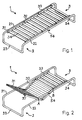
- FIG 1 shows a perspective view of an exemplary embodiment of the adjustable couch 1 according to the invention in a lying position, Figure 2 in an intermediate position.
- the bed 1 has a frame 2 comprising two parallel longitudinal bars 21, 22.
- the frame 2 is in one piece and has the shape of a double C, a longitudinal spar 21, 22 in each case forming the central part of the C and the two C's being connected at their ends by two transverse bars 23, 24.
- the frame 2 can be made, for example, of a hollow metal tube.
- the bed 1 has a bed surface 3, which is divided in the longitudinal direction into, for example, three segments 31-33: a head segment 31, a middle segment 32 and a foot segment 33. Two adjacent lying surface segments are each articulated to one another.
- the lying surface 3 or each of its segments 31-33 can include a slatted frame 34 known per se.
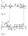
- FIGS. 3 and 4 show schematic side views of the bed 1 of FIGS. 1 and 2 in the lying position or in the intermediate position, the bed frame 2 being only indicated for the sake of clarity and in particular the longitudinal bar 21 facing the viewer is not shown.
- the head segment 31 is fastened to the longitudinal beam 31 so as to be rotatable about a horizontal axis A.
- the foot segment 33 is guided in the longitudinal spar 21, for example at two guide points C, D.
- the middle segment 32 is not attached to the longitudinal beam 21 in this exemplary embodiment.
- locking means 5 for reversibly fixing the distance between the head segment 31 and the foot segment 33 or the displacement x of the foot segment 33 are described.
- FIGS. 1 and 2 show a first embodiment of locking means 5, which is suitable for tubular longitudinal bars 21.
- a longitudinal spar 21 for example the bed 1 of FIGS. 1 and 2 is shown in FIG. 5 in a perspective, disclosed representation.
- FIG. 6 shows a perspective, exploded illustration of elements contained in the tubular longitudinal spar 21 of FIG. 5.
- the longitudinal spar 21 contains first fastening means 41, For example, a pivot bearing for a horizontal axis A rotatable mounting of the head segment 31.
- the pivot bearing 41 can be designed, for example, as a pivot, which in a corresponding blind hole 35 in the head segment 31 (see FIGS. 3, 4) intervenes.
- the longitudinal spar 21 further includes the second Fastening means 42 for guided along the longitudinal spar 21 Storage of the foot segment 33.
- This second Fastening means 42 are, for example, as two pins 42.1, 42.2 formed, which in corresponding blind holes 36.1, 36.2 in Engage foot segment 33. While in the embodiment of the Figures 5 and 6, the first fastening means 41 relative to Longitudinal spar 21 are immobile, are the second Fastening means 42 on one in the longitudinal spar 21 slidable carriage 43 out.
- the longitudinal spar 21 also includes locking means 5 for reversible setting of the distance between the first Fasteners 41 and the second fasteners 42.
- the locking means 5 are as with the second Fastening means 42 connected, on the carriage 43 located comb-shaped element 51 with teeth 52 and recesses 53 between them on the one hand and with the first fastening means 41 operatively connected pins 54 on the other hand trained. (Of course they could Teeth 52 of the comb-shaped element 51 upwards instead of downwards below.)
- the pin 54 is for engagement in the recesses 53 suitable and preferably projects as pivotable handle out of the longitudinal spar 21 (see FIG. 1, 2). He is on one in the longitudinal spar 21 about the longitudinal spar axis rotatable, but not slidably mounted roller 55 appropriate.
- the Locking means 5 for locking the distance between the first fastening means 41 and the second Fasteners 42 locked or unlocked.
- the comb-shaped element 51 is along the lateral surface of the roller 55 curved.
- the roller 55 can with a pin 61 at the head of the Longitudinal spar 21 be operatively connected that the pin 61 in the Locking position of the roller 55 protrudes from the longitudinal spar 21 and in the free position of the roller 55 essentially in the longitudinal spar 21 is sunk.
- a suitable mechanism 62 provides rotation of the roller 55.
- the pin 61 engages in a corresponding hole 37 in the Head segment 31 (see. Fig. 2-4) and serves as a fixative for reversible fixation of the head segment 31 in the Deck level. Such a fixation of the head segment 31 is Not theoretically necessary, but advantageous in practice.
- FIGS. 7 and 8 show a second embodiment of locking means 5 ', which is suitable for flat longitudinal bars 21'.
- the locking means 5 ' are shown in the locked state in FIGS. 7 (a) and 7 (b) and in the unlocked state in FIGS. 8 (a) and 8 (b).
- FIGS. 7 (a) and 8 (a) are views, FIGS. 7 (b) and 8 (b) are cross sections of the locking means 5 '.
- the locking means 5 'of Figures 7 and 8 include also a comb-shaped element 51 'with teeth 52' and intermediate recesses 53 '. In contrast to curved comb-shaped element 51 of the embodiment of FIG Figures 5 and 6, this comb-shaped element 51 'is flat. It is displaceable along the longitudinal bar 21 ' Carriage 43 'connected, on which, for example (not shown) second fastening means are attached, analogous to the embodiment of Figures 5 and 6. Furthermore include the locking means 5 'an eccentric 56', the Axis 57 'in the longitudinal spar 21' perpendicular to the longitudinal spar axis rotatably mounted and for engaging in the recesses 53 ' of the comb-shaped element 51 'is suitable.
- the push rod 59' can have a bearing element 25 ' a flange-shaped end in the longitudinal spar 21 '.
- the eccentric 56 ' is, for example, by means of a pivot 58' a push rod 59 'operatively connected such that a Displacement of the push rod 59 'along the longitudinal spar 21' causes the eccentric 56 'to rotate.
- the shift of the Push rod 59 ' is, for example, by means of a suitable position of the longitudinal spar 21 'attached lever 60' executed.
- the comb-shaped element 51 ' lies on the eccentric 56'.
- the comb-shaped element 51 ' lowered so that the axis 57 'of the eccentric 56' in the Recesses 53 'of the comb-shaped element 51' engages and the locking means 5 'are locked.
- An actuation of the Lever 60 ' causes the eccentric 56' to rotate.
- the comb-shaped element 51 ' is raised and gives the Eccentric axis 57 'free.
- the locking means 5, 5 'shown in Fig. 5-8 are as to understand non-limiting embodiments. at Knowledge of the invention is capable of the expert, further specify suitable locking means 5. It is also possible, instead of the gradual adjustment of the Lying surface 3 to provide a continuous adjustment. To would be, for example, instead of the positive locking means 5, 5 '. friction locking means suitable. In another Embodiment could the locking means 5 than in the longitudinal spar 21 permanently installed electric motor, which by means of a spindle, for example, the second fastening means 42 moved or locked. The locking means can only in a longitudinal spar 21 (or 21 ') or in both longitudinal spars 21, 22 (or 21 ', 22') are attached.
Landscapes
- Health & Medical Sciences (AREA)
- General Health & Medical Sciences (AREA)
- Nursing (AREA)
- Chairs For Special Purposes, Such As Reclining Chairs (AREA)
- Invalid Beds And Related Equipment (AREA)
- Special Chairs (AREA)
- Accommodation For Nursing Or Treatment Tables (AREA)
Applications Claiming Priority (2)
| Application Number | Priority Date | Filing Date | Title |
|---|---|---|---|
| CH5232001 | 2001-03-21 | ||
| CH5232001 | 2001-03-21 |
Publications (3)
| Publication Number | Publication Date |
|---|---|
| EP1243206A2 true EP1243206A2 (fr) | 2002-09-25 |
| EP1243206A3 EP1243206A3 (fr) | 2004-01-02 |
| EP1243206B1 EP1243206B1 (fr) | 2005-07-20 |
Family
ID=4518091
Family Applications (1)
| Application Number | Title | Priority Date | Filing Date |
|---|---|---|---|
| EP02405153A Expired - Lifetime EP1243206B1 (fr) | 2001-03-21 | 2002-03-01 | Meuble de couchage réglable et cadre pour un tel meuble |
Country Status (4)
| Country | Link |
|---|---|
| EP (1) | EP1243206B1 (fr) |
| AT (1) | ATE299656T1 (fr) |
| DE (1) | DE50203655D1 (fr) |
| HK (1) | HK1051302B (fr) |
Cited By (2)
| Publication number | Priority date | Publication date | Assignee | Title |
|---|---|---|---|---|
| EP3078300A1 (fr) | 2015-04-10 | 2016-10-12 | Tribù Nv | Couchette reglable |
| WO2022191784A1 (fr) * | 2021-03-11 | 2022-09-15 | CHOKWONGANUN, Suppharaj | Structure de support réglable |
Family Cites Families (5)
| Publication number | Priority date | Publication date | Assignee | Title |
|---|---|---|---|---|
| DE521742C (de) * | 1929-03-20 | 1931-03-26 | Paul Steinmann | Ruhebett |
| GB556353A (en) * | 1942-08-11 | 1943-09-30 | Whitfields Bedsteads Ltd | Improvements in or connected with positional invalid bedsteads, stretchers, or the like |
| FR1270426A (fr) * | 1960-10-18 | 1961-08-25 | Slumberland Group Ltd | Matelas formé de parties articulées entre elles |
| US3127783A (en) * | 1961-06-08 | 1964-04-07 | Anderson Co | Adjustable holding mechanism |
| NO305732B1 (no) * | 1996-04-11 | 1999-07-19 | Kjartan Alvestad | Reguleringsanordning for ligge- eller sittem°bel |
-
2002
- 2002-03-01 AT AT02405153T patent/ATE299656T1/de not_active IP Right Cessation
- 2002-03-01 EP EP02405153A patent/EP1243206B1/fr not_active Expired - Lifetime
- 2002-03-01 DE DE50203655T patent/DE50203655D1/de not_active Expired - Lifetime
-
2003
- 2003-03-25 HK HK03102170.5A patent/HK1051302B/zh not_active IP Right Cessation
Cited By (3)
| Publication number | Priority date | Publication date | Assignee | Title |
|---|---|---|---|---|
| EP3078300A1 (fr) | 2015-04-10 | 2016-10-12 | Tribù Nv | Couchette reglable |
| BE1022923B1 (nl) * | 2015-04-10 | 2016-10-19 | Tribu Nv | Verstelbaar ligbed |
| WO2022191784A1 (fr) * | 2021-03-11 | 2022-09-15 | CHOKWONGANUN, Suppharaj | Structure de support réglable |
Also Published As
| Publication number | Publication date |
|---|---|
| EP1243206B1 (fr) | 2005-07-20 |
| ATE299656T1 (de) | 2005-08-15 |
| DE50203655D1 (de) | 2005-08-25 |
| HK1051302A1 (en) | 2003-08-01 |
| EP1243206A3 (fr) | 2004-01-02 |
| HK1051302B (zh) | 2005-11-18 |
Similar Documents
| Publication | Publication Date | Title |
|---|---|---|
| DE102005052123B3 (de) | Lenksäule für ein Kraftfahrzeug | |
| DE3031318C2 (de) | Dachflächenfenster | |
| DE69613444T2 (de) | Sonnendach für Fahrzeug | |
| EP1989962B1 (fr) | Mécanisme synchrone pour chaises de bureau | |
| EP1708595A2 (fr) | Entrainement de meuble servant a ajuster une premiere partie d'un meuble par rapport a une deuxieme partie de ce meuble | |
| EP0396153A2 (fr) | Dispositif de réglage en hauteur pour sièges de véhicules | |
| DE10107196A1 (de) | Fahrzeugsitz, insbesondere Fluggastsitz | |
| DE2856695A1 (de) | Einstellbares stuetzteil an einem fahrzeugsitz | |
| DE102006009265B4 (de) | Gleitschiene für einen Fahrzeugsitz und Sitz, welcher eine solche Gleitschiene umfasst | |
| EP0313075A2 (fr) | Disposition de sièges-lits pour bus, wagons, avions et bateaux | |
| DE3737707A1 (de) | Verriegelbare senkrechtmarkise | |
| EP1243206B1 (fr) | Meuble de couchage réglable et cadre pour un tel meuble | |
| DE69704651T2 (de) | Laufradvorrichtung für Schiebetür | |
| DE2616802A1 (de) | Halter fuer lotrecht regelbare fahrzeugsitze | |
| DE8713662U1 (de) | Lattenrost | |
| DE8331237U1 (de) | Vorrichtung zur einstellung der position eines fahrzeugsitzes | |
| DE202015003363U1 (de) | Sitzmöbel mit Verriegelungsvorrichtung | |
| DE2032833A1 (de) | Vorrichtung zum Feststellen eines ver stellbaren Fahrzeugsitzes oder der schwenk baren Ruckenlehne eines Fahrzeugsitzes in wahlbarer Position | |
| EP2596721B1 (fr) | Chaise et agencement de siège | |
| DE2505972A1 (de) | Sitzanordnung fuer ein fahrzeug mit einem in der sitzflaechenneigung verstellbaren sitz | |
| DE68911898T2 (de) | Klappbare struktur. | |
| DE2331943C3 (de) | Zahnärztlicher Patientenstuhl mit verstellbarer Kopfstütze | |
| DE10124282C2 (de) | Sitzmöbel | |
| DE4342016A1 (de) | Vorrichtung zum Verstellen der Höhe und/oder Neigung einer Tischplatte | |
| DE202007003808U1 (de) | Seitengitter |
Legal Events
| Date | Code | Title | Description |
|---|---|---|---|
| PUAI | Public reference made under article 153(3) epc to a published international application that has entered the european phase |
Free format text: ORIGINAL CODE: 0009012 |
|
| AK | Designated contracting states |
Kind code of ref document: A2 Designated state(s): AT BE CH CY DE DK ES FI FR GB GR IE IT LI LU MC NL PT SE TR |
|
| AX | Request for extension of the european patent |
Free format text: AL;LT;LV;MK;RO;SI |
|
| PUAL | Search report despatched |
Free format text: ORIGINAL CODE: 0009013 |
|
| AK | Designated contracting states |
Kind code of ref document: A3 Designated state(s): AT BE CH CY DE DK ES FI FR GB GR IE IT LI LU MC NL PT SE TR |
|
| AX | Request for extension of the european patent |
Extension state: AL LT LV MK RO SI |
|
| 17P | Request for examination filed |
Effective date: 20040225 |
|
| 17Q | First examination report despatched |
Effective date: 20040617 |
|
| AKX | Designation fees paid |
Designated state(s): AT BE CH CY DE DK ES FI FR GB GR IE IT LI LU MC NL PT SE TR |
|
| GRAP | Despatch of communication of intention to grant a patent |
Free format text: ORIGINAL CODE: EPIDOSNIGR1 |
|
| GRAS | Grant fee paid |
Free format text: ORIGINAL CODE: EPIDOSNIGR3 |
|
| GRAA | (expected) grant |
Free format text: ORIGINAL CODE: 0009210 |
|
| AK | Designated contracting states |
Kind code of ref document: B1 Designated state(s): AT BE CH CY DE DK ES FI FR GB GR IE IT LI LU MC NL PT SE TR |
|
| PG25 | Lapsed in a contracting state [announced via postgrant information from national office to epo] |
Ref country code: IE Free format text: LAPSE BECAUSE OF FAILURE TO SUBMIT A TRANSLATION OF THE DESCRIPTION OR TO PAY THE FEE WITHIN THE PRESCRIBED TIME-LIMIT Effective date: 20050720 Ref country code: FI Free format text: LAPSE BECAUSE OF FAILURE TO SUBMIT A TRANSLATION OF THE DESCRIPTION OR TO PAY THE FEE WITHIN THE PRESCRIBED TIME-LIMIT Effective date: 20050720 Ref country code: TR Free format text: LAPSE BECAUSE OF FAILURE TO SUBMIT A TRANSLATION OF THE DESCRIPTION OR TO PAY THE FEE WITHIN THE PRESCRIBED TIME-LIMIT Effective date: 20050720 |
|
| REG | Reference to a national code |
Ref country code: GB Ref legal event code: FG4D Free format text: NOT ENGLISH |
|
| REG | Reference to a national code |
Ref country code: CH Ref legal event code: EP |
|
| REG | Reference to a national code |
Ref country code: IE Ref legal event code: FG4D Free format text: LANGUAGE OF EP DOCUMENT: GERMAN |
|
| REF | Corresponds to: |
Ref document number: 50203655 Country of ref document: DE Date of ref document: 20050825 Kind code of ref document: P |
|
| PG25 | Lapsed in a contracting state [announced via postgrant information from national office to epo] |
Ref country code: GR Free format text: LAPSE BECAUSE OF FAILURE TO SUBMIT A TRANSLATION OF THE DESCRIPTION OR TO PAY THE FEE WITHIN THE PRESCRIBED TIME-LIMIT Effective date: 20051020 Ref country code: DK Free format text: LAPSE BECAUSE OF FAILURE TO SUBMIT A TRANSLATION OF THE DESCRIPTION OR TO PAY THE FEE WITHIN THE PRESCRIBED TIME-LIMIT Effective date: 20051020 Ref country code: SE Free format text: LAPSE BECAUSE OF FAILURE TO SUBMIT A TRANSLATION OF THE DESCRIPTION OR TO PAY THE FEE WITHIN THE PRESCRIBED TIME-LIMIT Effective date: 20051020 |
|
| PG25 | Lapsed in a contracting state [announced via postgrant information from national office to epo] |
Ref country code: ES Free format text: LAPSE BECAUSE OF FAILURE TO SUBMIT A TRANSLATION OF THE DESCRIPTION OR TO PAY THE FEE WITHIN THE PRESCRIBED TIME-LIMIT Effective date: 20051031 |
|
| REG | Reference to a national code |
Ref country code: CH Ref legal event code: NV Representative=s name: SCHNEIDER FELDMANN AG PATENT- UND MARKENANWAELTE |
|
| REG | Reference to a national code |
Ref country code: HK Ref legal event code: GR Ref document number: 1051302 Country of ref document: HK |
|
| PG25 | Lapsed in a contracting state [announced via postgrant information from national office to epo] |
Ref country code: PT Free format text: LAPSE BECAUSE OF FAILURE TO SUBMIT A TRANSLATION OF THE DESCRIPTION OR TO PAY THE FEE WITHIN THE PRESCRIBED TIME-LIMIT Effective date: 20051221 |
|
| GBT | Gb: translation of ep patent filed (gb section 77(6)(a)/1977) |
Effective date: 20051207 |
|
| REG | Reference to a national code |
Ref country code: IE Ref legal event code: FD4D |
|
| PG25 | Lapsed in a contracting state [announced via postgrant information from national office to epo] |
Ref country code: LU Free format text: LAPSE BECAUSE OF NON-PAYMENT OF DUE FEES Effective date: 20060331 Ref country code: MC Free format text: LAPSE BECAUSE OF NON-PAYMENT OF DUE FEES Effective date: 20060331 |
|
| ET | Fr: translation filed | ||
| PLBE | No opposition filed within time limit |
Free format text: ORIGINAL CODE: 0009261 |
|
| STAA | Information on the status of an ep patent application or granted ep patent |
Free format text: STATUS: NO OPPOSITION FILED WITHIN TIME LIMIT |
|
| 26N | No opposition filed |
Effective date: 20060421 |
|
| PG25 | Lapsed in a contracting state [announced via postgrant information from national office to epo] |
Ref country code: CY Free format text: LAPSE BECAUSE OF FAILURE TO SUBMIT A TRANSLATION OF THE DESCRIPTION OR TO PAY THE FEE WITHIN THE PRESCRIBED TIME-LIMIT Effective date: 20050720 |
|
| PGFP | Annual fee paid to national office [announced via postgrant information from national office to epo] |
Ref country code: FR Payment date: 20100402 Year of fee payment: 9 |
|
| PGFP | Annual fee paid to national office [announced via postgrant information from national office to epo] |
Ref country code: AT Payment date: 20100311 Year of fee payment: 9 Ref country code: GB Payment date: 20100322 Year of fee payment: 9 |
|
| PGFP | Annual fee paid to national office [announced via postgrant information from national office to epo] |
Ref country code: DE Payment date: 20100419 Year of fee payment: 9 Ref country code: IT Payment date: 20100326 Year of fee payment: 9 Ref country code: NL Payment date: 20100315 Year of fee payment: 9 |
|
| PGFP | Annual fee paid to national office [announced via postgrant information from national office to epo] |
Ref country code: BE Payment date: 20100506 Year of fee payment: 9 Ref country code: CH Payment date: 20100624 Year of fee payment: 9 |
|
| BERE | Be: lapsed |
Owner name: *REICHELT WOLFGANG Effective date: 20110331 |
|
| REG | Reference to a national code |
Ref country code: NL Ref legal event code: V1 Effective date: 20111001 |
|
| REG | Reference to a national code |
Ref country code: CH Ref legal event code: PL |
|
| GBPC | Gb: european patent ceased through non-payment of renewal fee |
Effective date: 20110301 |
|
| PG25 | Lapsed in a contracting state [announced via postgrant information from national office to epo] |
Ref country code: AT Free format text: LAPSE BECAUSE OF NON-PAYMENT OF DUE FEES Effective date: 20110301 |
|
| REG | Reference to a national code |
Ref country code: FR Ref legal event code: ST Effective date: 20111130 |
|
| PG25 | Lapsed in a contracting state [announced via postgrant information from national office to epo] |
Ref country code: BE Free format text: LAPSE BECAUSE OF NON-PAYMENT OF DUE FEES Effective date: 20110331 |
|
| PG25 | Lapsed in a contracting state [announced via postgrant information from national office to epo] |
Ref country code: LI Free format text: LAPSE BECAUSE OF NON-PAYMENT OF DUE FEES Effective date: 20110331 Ref country code: NL Free format text: LAPSE BECAUSE OF NON-PAYMENT OF DUE FEES Effective date: 20111001 Ref country code: DE Free format text: LAPSE BECAUSE OF NON-PAYMENT OF DUE FEES Effective date: 20111001 Ref country code: FR Free format text: LAPSE BECAUSE OF NON-PAYMENT OF DUE FEES Effective date: 20110331 Ref country code: CH Free format text: LAPSE BECAUSE OF NON-PAYMENT OF DUE FEES Effective date: 20110331 |
|
| REG | Reference to a national code |
Ref country code: DE Ref legal event code: R119 Ref document number: 50203655 Country of ref document: DE Effective date: 20111001 |
|
| PG25 | Lapsed in a contracting state [announced via postgrant information from national office to epo] |
Ref country code: GB Free format text: LAPSE BECAUSE OF NON-PAYMENT OF DUE FEES Effective date: 20110301 Ref country code: IT Free format text: LAPSE BECAUSE OF NON-PAYMENT OF DUE FEES Effective date: 20110301 |