EP1243372B1 - Funkenerosionsmaschine mit einer Vorrichtung zum Behandeln der Bearbeitungsflüssigkeit - Google Patents
Funkenerosionsmaschine mit einer Vorrichtung zum Behandeln der Bearbeitungsflüssigkeit Download PDFInfo
- Publication number
- EP1243372B1 EP1243372B1 EP02251993A EP02251993A EP1243372B1 EP 1243372 B1 EP1243372 B1 EP 1243372B1 EP 02251993 A EP02251993 A EP 02251993A EP 02251993 A EP02251993 A EP 02251993A EP 1243372 B1 EP1243372 B1 EP 1243372B1
- Authority
- EP
- European Patent Office
- Prior art keywords
- electric discharge
- filtration pressure
- filter
- discharge machine
- sensor
- Prior art date
- Legal status (The legal status is an assumption and is not a legal conclusion. Google has not performed a legal analysis and makes no representation as to the accuracy of the status listed.)
- Expired - Lifetime
Links
- 239000012530 fluid Substances 0.000 title claims description 24
- 238000012545 processing Methods 0.000 title claims description 23
- 238000001914 filtration Methods 0.000 claims description 47
- 230000007704 transition Effects 0.000 claims description 13
- 238000001514 detection method Methods 0.000 claims description 6
- 239000013505 freshwater Substances 0.000 claims description 4
- 238000003754 machining Methods 0.000 description 25
- XLYOFNOQVPJJNP-UHFFFAOYSA-N water Substances O XLYOFNOQVPJJNP-UHFFFAOYSA-N 0.000 description 23
- 230000006870 function Effects 0.000 description 6
- 239000010802 sludge Substances 0.000 description 6
- 239000000725 suspension Substances 0.000 description 5
- 238000010586 diagram Methods 0.000 description 4
- 238000005516 engineering process Methods 0.000 description 4
- 238000012423 maintenance Methods 0.000 description 3
- 238000012790 confirmation Methods 0.000 description 2
- 230000007423 decrease Effects 0.000 description 2
- 230000003247 decreasing effect Effects 0.000 description 2
- 239000000428 dust Substances 0.000 description 2
- 238000012544 monitoring process Methods 0.000 description 2
- 238000005070 sampling Methods 0.000 description 2
- 230000005540 biological transmission Effects 0.000 description 1
- 238000006243 chemical reaction Methods 0.000 description 1
- 238000005286 illumination Methods 0.000 description 1
- 238000009413 insulation Methods 0.000 description 1
- 230000002045 lasting effect Effects 0.000 description 1
- 239000004973 liquid crystal related substance Substances 0.000 description 1
- 230000007774 longterm Effects 0.000 description 1
- 238000000034 method Methods 0.000 description 1
- 230000002035 prolonged effect Effects 0.000 description 1
- 238000011144 upstream manufacturing Methods 0.000 description 1
- 230000000007 visual effect Effects 0.000 description 1
- 239000002699 waste material Substances 0.000 description 1
Images


Classifications
-
- B—PERFORMING OPERATIONS; TRANSPORTING
- B23—MACHINE TOOLS; METAL-WORKING NOT OTHERWISE PROVIDED FOR
- B23H—WORKING OF METAL BY THE ACTION OF A HIGH CONCENTRATION OF ELECTRIC CURRENT ON A WORKPIECE USING AN ELECTRODE WHICH TAKES THE PLACE OF A TOOL; SUCH WORKING COMBINED WITH OTHER FORMS OF WORKING OF METAL
- B23H1/00—Electrical discharge machining, i.e. removing metal with a series of rapidly recurring electrical discharges between an electrode and a workpiece in the presence of a fluid dielectric
- B23H1/10—Supply or regeneration of working media
Definitions
- the present invention relates to an electric discharge machine with a work fluid processing device, and particularly to technology for safely and easily performing the maintenance and management of filters in such a working fluid processing device.
- a working fluid (usually water) is used for maintaining the insulation between an electrode and a work piece, and eliminating chips generated pursuant to machining.
- the working fluid impure water
- chips or sludge such as dust that crept in
- the working fluid cleaned with the filter is re-supplied to the processing unit via a fresh-water tank for storing the clean working fluid.
- a filter becomes gradually clogged pursuant to the prolonged use thereof, and the pressure applied to the filter increases in accordance with the clogging.
- a dangerous state is generated when the increase in pressure exceeds the limit, and, as a result, it is not unusual for accidents to occur which are caused by the breakage or falling-off of filters and hoses.
- a water pressure gauge for measuring filtration pressure to be disposed in the flow path between a filter pump, which aspirates impure water from a holding tank storing such impure water generated at the processing unit and supplies the filter with this impure water, and the filter, and an operator visually confirm the pressure indication of such water pressure gauge.
- a filtration pressure appearing between a filter and a filter pump during a continuous machining or immediately after the completion of machining differs from the filtration pressure at a time a suspension time has elapsed after the stoppage of the continuous machining, even if the degree of progress in filter clogging is the same. This is because the sludge attached to the filter element inside the filter is detached upon the depressurization caused by the suspension of the pump, or the attachment of such sludge is temporarily loose.
- An electric discharge machine with a working fluid processing device with a sensor for detecting filtration pressure of a filter for working fluid, according to the preamble of claim 1, is known from US-A-5,298,161 .
- An object of the present invention is to provide an electric discharge machine with a work fluid processing device which can provide an operator with information necessary for determining filter replacement time.
- the invention is defined in attached claim 1.
- a pressure detection sensor may be disposed between a filter pump and a filter in a working fluid processing device of an electric discharge machine, and, by processing the water pressure information with a controller, providing an operator with useful information for determining filter replacement time.
- a sensor for detecting a filtration pressure of the filter is provided, and the water pressure transition is recorded based on the output of the sensor.
- an operator can know the filtration pressure of a filter from the present time (time of confirming the recorded contents) by tracing an elapsed time. Therefore, unlike conventional technology where only an instantaneous value at the time of visually checking a water pressure gauge can be confirmed, the progress of filter clogging can be acknowledged with ease.
- a sensor for detecting the filtration pressure of the filter and display means for displaying the filtration pressure of the filter are provided, and the water pressure transition is displayed on the display means based on the output of the sensor.
- a point of X-Y relationship with the X-axis being the time and the Y-axis being the filter pressure, may be plotted on a monitor screen in a graph format. The operator is thereby able to know the filtration pressure of the filter, at a glance, from the present time (time of confirming the recorded contents) by tracing an elapsed time.
- storage means for storing, at prescribed time intervals, filtration pressure detected by a sensor may be provided so as to display the stored filtration pressure. Moreover, displaying of the filtration pressure detected by the sensor on the display means may be renewed only at the time of processing.
- information function of a further anomaly may be added to each of the foregoing embodiments.
- information on an anomaly may be made when the sensor detects a filtration pressure exceeding a predetermined reference. This will be in addition to the information on an anomaly made according to the invention when the sensor detects, during operation after the commencement of operation, a filtration pressure falling below the filtration pressure detected at the time of the previous filtration pressure detection.
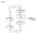
- Fig. 2 shows the outline of the overall structure of an embodiment according to the present invention.
- a processing unit for performing wire electric discharge machining in the working fluid
- a holding tank for temporarily storing the working fluid (impure water) containing processing waste generated therein or sludge such as dust that crept in
- a pump (sometimes referred to as a filter pump; hereinafter the same) for aspirating the impure water from the holding tank and supplying such impure water to the filter
- a filter for receiving the working fluid supplied from the pump
- a fresh-water tank for temporarily storing the working fluid cleaned with the filter, and the working fluid circulates in the direction represented with the arrows.
- a sensor for detecting a filtration pressure that is, water pressure applied to a filter, is disposed at the upstream of the filter (between the filter and pump).
- This sensor outputs detected water pressure as an analog voltage or an analog current signal, and this type of water pressure sensor is commercially available, and may be obtained at a relatively low cost.
- the output of this sensor is sent to the controller and AD converted, and the detected transition of the filtration pressure of the filter is recorded by the sensor. Moreover, data representing the transition of a filtration pressure is stored in the controller and displayed in the form of graph on a display device (CRT, liquid crystal display device, printer, etc.)
- Fig. 3 The principal portions of the controller and display device are displayed in Fig. 3 in the form of block diagram.
- a CPU central processing unit
- ROM read-only memory
- RAM random access memory
- DI/DO digital signal input/output device
- the CPU fulfills processor function for numerical control as well as processor function for various applications including processing relating to storage, displaying, monitoring and so on of a filtration pressure, which are described later.
- the ROM stores a basic program for controlling the overall system, a system program for the numerical control function, and a program for processing relating to the storage, displaying, monitoring and so on of the filtration pressure.
- the RAM is used as a memory for temporarily storing data operated by the CPU, and for storing a processing program for a work piece read from the handy file and so on.
- the DI/DO is a digital input/output device connected to various actuators and various sensors of a working fluid flow controlling device, an electric discharge machining power source and so on.
- the sensor employed in the present embodiment is connected to the DI/DO via the AD converter.
- the control circuit is connected to the respective servomotors of the X, Y and Z axes and U and V axes for causing the wire electrode to move relative to the work piece in order to perform machining.
- the CPU activates the electric discharge machining power source under the established electric discharge machining conditions, drives the servomotors of the respective X, Y, Z; U, V axes via the control circuit in accordance with the processing program stored in the RAM, and performs electric discharge machining while moving the wire electrode relative to the work piece.
- the recording and display of the filtration pressure are conducted as follows.
- the water pressure sensor disposed between the filter pump and the filter outputs a signal roughly proportionate to the water pressure in an analog voltage or an analog current. This signal is converted into a digital signal with the AD converter of the controller. This data transmission and AD conversion are constantly performed.
- the CPU of the controller incorporates this AD-converted data via the DI/DO (digital signal input/output device) at a fixed sampling period T, and sequentially stores this in the RAM.
- the stored data is read immediately thereafter, and the filter pressure Y for each sampling period T is -plotted with respect to the time coordinate axis X on the monitor screen (CRT screen) in a graph format.
- the stored contents may be stored in the RAM or another memory and, instead of the automatic plotting, the operator may read and confirm the data upon manually operating the controller.
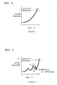
- the filter pressure will show a transition of gradual increase as illustrated in Graph 1 of Fig. 4 if machining is continued, and will eventually reach the pressure (longevity pressure) indicating longevity, unless a problem such as a rupture occurs. Further, in Graph 1, the latest plotting point shows that the filtration pressure has exceeded the longevity pressure, but has not resulted in a rupture yet. As this state is already in a warning zone, it is desirable that the filter be replaced immediately. This phenomenon may appear in the case of a long-term continuous operation.
- a CPU may determine on a case-by-case basis regarding whether the latest detection output incorporated exceeds the predetermined longevity pressure (stored in the RAM), and output an alarm if the determination of the CPU result in YES.
- an alarm may be outputted when the sensor detects, during operation after the commencement of operation, a filtration pressure falling below the filtration pressure detected at the time of previous filtration pressure detection.
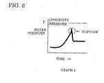
- This case for example, is when a rupture accident occurs due to some reason (insufficient durability performance of the filter, for instance) and the water pressure rapidly decreases as shown in Graph 3 of Fig. 6 .
- this judgment is made "during operation subsequent to the start of operation" in order to prevent the alarm from being outputted in correspondence with symbol B in Graph 2.
- an alarm is not outputted by comparing the value of the first plot subsequent to the restart of machining corresponding to symbol B with the value of the previous plot (corresponding to symbol A)-prior to such restart.
- the controller informs of an anomaly by means of displaying on the CRT screen, sound, or illumination of a red lamp in accordance with a prescribed program. With this information, an operator can immediately know the occurrence of an anomaly.
- the power source may also be turned off pursuant to such alarm output.
- the reliability of maintenance of filters for sludge filtration used by a working fluid processing device in a wire cut electric discharge machine can be improved, and safety can be secured easily as a result thereof. Since the change in filter pressure is recorded or displayed on a monitor, it is possible to easily confirm whether the pressure comes close to the replacement pressure even in a case where the pressure has once decreased during suspension of machining. It is therefore possible to prevent ruptures even during a nighttime operation or unattended operation thereafter.
Landscapes
- Engineering & Computer Science (AREA)
- Mechanical Engineering (AREA)
- Electrical Discharge Machining, Electrochemical Machining, And Combined Machining (AREA)
- Filtration Of Liquid (AREA)
Claims (6)
- Elektroerosionsmaschine mit einer Arbeitsfluid-Bearbeitungsvorrichtung, die angeordnet ist, um eine Elektroerosionsbearbeitungseinheit über einen Zufuhrkanal mit in einem Frischwassertank aufbewahrtem Arbeitsfluid zu versorgen und um in der Elektroerosionsbearbeitungseinheit verwendetes Arbeitsfluid vorübergehend in einem Aufbewahrungsbehälter aufzubewahren, wobei bewirkt wird, dass Arbeitsfluid über eine Pumpe und ein Filter zu dem Frischwassertank rückgeführt wird, umfassend:einen Sensor zum Detektieren eines Filtrationsdrucks des Filters;gekennzeichnet durch:Mittel zum Aufzeichnen des Filtrationsdruckübergangs auf der Grundlage des Ausgangs des Sensors; undMittel zum Anzeigen einer Anomalie, wenn der Sensor nach Betriebsbeginn während des Betriebs einen Filtrationsdruck detektiert, der unter den Filtrationsdruck abfällt, welcher zum Zeitpunkt der vorhergehenden Filtrationsdruckdetektion detektiert wurde.
- Elektroerosionsmaschine nach Anspruch 1, ferner umfassend Anzeigemittel, die zum Anzeigen des Filtrationsdrucks des Filters angeordnet sind, derart, dass der Übergang des Filtrationsdrucks auf den Anzeigemitteln auf der Grundlage des Ausgangs des Sensors angezeigt wird.
- Elektroerosionsmaschine nach Anspruch 1 oder 2, wobei Speichermittel zum Speichern des durch den Sensor detektierten Filtrationsdrucks in vorgegebenen Zeitabständen vorgesehen sind und der gespeicherte Filtrationsdruck angezeigt wird.
- Elektroerosionsmaschine nach Anspruch 1, 2 oder 3, die angeordnet ist, um derart betrieben zu werden, dass die Aufzeichnung oder Anzeige des durch den Sensor detektierten Filtrationsdrucks nur während der Bearbeitung aktualisiert wird.
- Elektroerosionsmaschine nach einem beliebigen der Ansprüche 1 bis 4, welche angeordnet ist, um eine Anomalie anzuzeigen, wenn der Sensor einen Filtrationsdruck detektiert, der einen vorgegebenen Referenzwert überschreitet.
- Elektroerosionsmaschine nach einem beliebigen der Ansprüche 1 bis 5, wobei die Elektroerosionsmaschine eine Drahtelektroerosionsmaschine ist.
Applications Claiming Priority (2)
| Application Number | Priority Date | Filing Date | Title |
|---|---|---|---|
| JP2001083119A JP3572027B2 (ja) | 2001-03-22 | 2001-03-22 | ワイヤ放電機の加工液処理装置 |
| JP2001083119 | 2001-03-22 |
Publications (3)
| Publication Number | Publication Date |
|---|---|
| EP1243372A2 EP1243372A2 (de) | 2002-09-25 |
| EP1243372A3 EP1243372A3 (de) | 2004-12-08 |
| EP1243372B1 true EP1243372B1 (de) | 2010-07-21 |
Family
ID=18938978
Family Applications (1)
| Application Number | Title | Priority Date | Filing Date |
|---|---|---|---|
| EP02251993A Expired - Lifetime EP1243372B1 (de) | 2001-03-22 | 2002-03-20 | Funkenerosionsmaschine mit einer Vorrichtung zum Behandeln der Bearbeitungsflüssigkeit |
Country Status (3)
| Country | Link |
|---|---|
| US (1) | US6683269B2 (de) |
| EP (1) | EP1243372B1 (de) |
| JP (1) | JP3572027B2 (de) |
Cited By (1)
| Publication number | Priority date | Publication date | Assignee | Title |
|---|---|---|---|---|
| CN108695190A (zh) * | 2017-04-07 | 2018-10-23 | 矽品精密工业股份有限公司 | 清洗设备 |
Families Citing this family (8)
| Publication number | Priority date | Publication date | Assignee | Title |
|---|---|---|---|---|
| JP3779289B2 (ja) * | 2003-07-31 | 2006-05-24 | ファナック株式会社 | 放電加工用の加工液処理装置 |
| US20050218089A1 (en) * | 2004-03-30 | 2005-10-06 | General Electric Company | Flushing and filtering system for electroerosion machining |
| JP6110353B2 (ja) | 2014-10-06 | 2017-04-05 | ファナック株式会社 | フィルタの交換時期の予測機能を有するワイヤ放電加工機 |
| JP6017525B2 (ja) * | 2014-12-17 | 2016-11-02 | ファナック株式会社 | 消耗品交換機能を有するワイヤ放電加工機用制御装置 |
| CN106392220A (zh) * | 2016-11-20 | 2017-02-15 | 嘉善霸器机械制造有限公司 | 一种电火花线切割伺服驱动器 |
| EP3375556B1 (de) * | 2017-03-15 | 2023-02-22 | Agie Charmilles SA | Selbstlernende filterlebensdauerschätzverfahren |
| JP6564439B2 (ja) * | 2017-09-20 | 2019-08-21 | ファナック株式会社 | 加工液処理装置および加工液処理装置の制御方法 |
| EP4201569A4 (de) | 2020-09-28 | 2024-10-02 | Fanuc Corporation | Lebensdauervorhersagevorrichtung und werkzeugmaschine |
Family Cites Families (7)
| Publication number | Priority date | Publication date | Assignee | Title |
|---|---|---|---|---|
| JPH02131821A (ja) * | 1988-11-04 | 1990-05-21 | Fanuc Ltd | 状態表示を行うワイヤ放電加工装置 |
| JPH05504722A (ja) * | 1991-01-07 | 1993-07-22 | エロソニック・アクチェンゲゼルシャフト | 電気浸食または電解加工機械の使用液を浄化する装置 |
| JPH052842A (ja) | 1991-06-25 | 1993-01-08 | Sony Corp | 軟判定復号回路 |
| JPH05185325A (ja) * | 1992-01-10 | 1993-07-27 | Mitsubishi Electric Corp | 放電加工装置 |
| JPH0731819A (ja) | 1993-07-23 | 1995-02-03 | Nippon Steel Corp | バグフィルタ集塵機の性能監視装置及び方法 |
| US5434381A (en) * | 1993-09-13 | 1995-07-18 | T-Star Industrial Electronics, Inc. | Apparatus for filtering machining liquid of an electrical discharge machine |
| JPH1137917A (ja) | 1997-07-22 | 1999-02-12 | Honda Motor Co Ltd | フィルターの試験装置 |
-
2001
- 2001-03-22 JP JP2001083119A patent/JP3572027B2/ja not_active Expired - Lifetime
-
2002
- 2002-03-18 US US10/098,491 patent/US6683269B2/en not_active Expired - Lifetime
- 2002-03-20 EP EP02251993A patent/EP1243372B1/de not_active Expired - Lifetime
Cited By (1)
| Publication number | Priority date | Publication date | Assignee | Title |
|---|---|---|---|---|
| CN108695190A (zh) * | 2017-04-07 | 2018-10-23 | 矽品精密工业股份有限公司 | 清洗设备 |
Also Published As
| Publication number | Publication date |
|---|---|
| EP1243372A2 (de) | 2002-09-25 |
| US20020134759A1 (en) | 2002-09-26 |
| US6683269B2 (en) | 2004-01-27 |
| JP2002283146A (ja) | 2002-10-03 |
| JP3572027B2 (ja) | 2004-09-29 |
| EP1243372A3 (de) | 2004-12-08 |
Similar Documents
| Publication | Publication Date | Title |
|---|---|---|
| EP3009218B1 (de) | Drahterosionsmaschine mit abschätzfunktion zur filterlebensdauer | |
| JP3681733B2 (ja) | 数値制御装置 | |
| EP1243372B1 (de) | Funkenerosionsmaschine mit einer Vorrichtung zum Behandeln der Bearbeitungsflüssigkeit | |
| JP4542819B2 (ja) | 油圧機械、油圧機械の健康状態を監視するためのシステム及び方法 | |
| US6260427B1 (en) | Diagnostic rule tool condition monitoring system | |
| US20060259273A1 (en) | Filter monitoring system | |
| WO2004085027A1 (en) | System comprising a filter with a replaceable filter element, filter element for use in a system of this type, and method for determining a technical state of a replaceable filter element of this type | |
| EP0417289B1 (de) | Elektrische entladungsmaschine mit anzeige der regelungsdaten | |
| KR940002886B1 (ko) | 유압 시스템에서 예상되는 고장을 검출하는 방법 및 장치 | |
| CN215842110U (zh) | 一种袋式除尘器自动监测装置 | |
| JP3857187B2 (ja) | シリンダの動作状態監視装置 | |
| US6917891B2 (en) | Systems and methods for diagnosing and predicting fluid flow systems using sensors | |
| JP3176290B2 (ja) | フィルタの管理装置 | |
| JP5594118B2 (ja) | アーク溶接装置およびアーク溶接電源装置および溶接用トーチ | |
| CN213775560U (zh) | 一种空气滤清器 | |
| JP4264733B2 (ja) | 建設機械の表示装置 | |
| JP2010240541A (ja) | 建設機械のフィルタ目詰まり検出装置 | |
| KR100600015B1 (ko) | 공작기계의 공구이상 검출 방법 | |
| JP2001147713A (ja) | 稼働管理システムおよび稼働管理方法並びに記憶媒体 | |
| JP2754266B2 (ja) | 工具データ集中管理機能を有する数値制御装置 | |
| CN212723704U (zh) | 一种刀具使用次数的监控系统 | |
| KR940009541B1 (ko) | 디젤엔진의 운전감시 장치 및 그 제어방법 | |
| JP3294414B2 (ja) | 工作機械における工具寿命検知方法 | |
| JP2766099B2 (ja) | 油圧回路の監視方式 | |
| JP2003320698A (ja) | サーマルヘッドのチェック方法およびチェック装置 |
Legal Events
| Date | Code | Title | Description |
|---|---|---|---|
| PUAI | Public reference made under article 153(3) epc to a published international application that has entered the european phase |
Free format text: ORIGINAL CODE: 0009012 |
|
| AK | Designated contracting states |
Kind code of ref document: A2 Designated state(s): AT BE CH CY DE DK ES FI FR GB GR IE IT LI LU MC NL PT SE TR |
|
| AX | Request for extension of the european patent |
Free format text: AL;LT;LV;MK;RO;SI |
|
| PUAL | Search report despatched |
Free format text: ORIGINAL CODE: 0009013 |
|
| AK | Designated contracting states |
Kind code of ref document: A3 Designated state(s): AT BE CH CY DE DK ES FI FR GB GR IE IT LI LU MC NL PT SE TR |
|
| AX | Request for extension of the european patent |
Extension state: AL LT LV MK RO SI |
|
| 17P | Request for examination filed |
Effective date: 20050309 |
|
| AKX | Designation fees paid |
Designated state(s): CH LI |
|
| REG | Reference to a national code |
Ref country code: DE Ref legal event code: 8566 |
|
| 17Q | First examination report despatched |
Effective date: 20070216 |
|
| RTI1 | Title (correction) |
Free format text: ELECTRIC DISCHARGE MACHINE WITH WORKING FLUID PROCESSING DEVICE. |
|
| GRAP | Despatch of communication of intention to grant a patent |
Free format text: ORIGINAL CODE: EPIDOSNIGR1 |
|
| GRAS | Grant fee paid |
Free format text: ORIGINAL CODE: EPIDOSNIGR3 |
|
| GRAA | (expected) grant |
Free format text: ORIGINAL CODE: 0009210 |
|
| AK | Designated contracting states |
Kind code of ref document: B1 Designated state(s): CH LI |
|
| REG | Reference to a national code |
Ref country code: CH Ref legal event code: EP |
|
| RAP2 | Party data changed (patent owner data changed or rights of a patent transferred) |
Owner name: FANUC CORPORATION |
|
| REG | Reference to a national code |
Ref country code: CH Ref legal event code: PFA Owner name: FANUC CORPORATION Free format text: FANUC LTD#3580, SHIBOKUSA, AZA-KOMANBA, OSHINO-MURA#MINAMITSURU-GUN, YAMANASHI 401-0597 (JP) -TRANSFER TO- FANUC CORPORATION#3580 SHIBOKUSA AZA-KOMANBA OSHINO-MURA MINAMITSURU-GUN#YAMANASHI 401-0597 (JP) Ref country code: CH Ref legal event code: NV Representative=s name: R. A. EGLI & CO. PATENTANWAELTE |
|
| PLBE | No opposition filed within time limit |
Free format text: ORIGINAL CODE: 0009261 |
|
| STAA | Information on the status of an ep patent application or granted ep patent |
Free format text: STATUS: NO OPPOSITION FILED WITHIN TIME LIMIT |
|
| 26N | No opposition filed |
Effective date: 20110426 |
|
| PGFP | Annual fee paid to national office [announced via postgrant information from national office to epo] |
Ref country code: CH Payment date: 20210317 Year of fee payment: 20 |
|
| REG | Reference to a national code |
Ref country code: CH Ref legal event code: PL |