EP1243390A2 - Verbundblatt für ein Reifenvulkanisierformwerkzeug - Google Patents
Verbundblatt für ein Reifenvulkanisierformwerkzeug Download PDFInfo
- Publication number
- EP1243390A2 EP1243390A2 EP02100259A EP02100259A EP1243390A2 EP 1243390 A2 EP1243390 A2 EP 1243390A2 EP 02100259 A EP02100259 A EP 02100259A EP 02100259 A EP02100259 A EP 02100259A EP 1243390 A2 EP1243390 A2 EP 1243390A2
- Authority
- EP
- European Patent Office
- Prior art keywords
- blade
- strip
- blade portions
- composite
- portions
- Prior art date
- Legal status (The legal status is an assumption and is not a legal conclusion. Google has not performed a legal analysis and makes no representation as to the accuracy of the status listed.)
- Granted
Links
Images


Classifications
-
- B—PERFORMING OPERATIONS; TRANSPORTING
- B29—WORKING OF PLASTICS; WORKING OF SUBSTANCES IN A PLASTIC STATE IN GENERAL
- B29D—PRODUCING PARTICULAR ARTICLES FROM PLASTICS OR FROM SUBSTANCES IN A PLASTIC STATE
- B29D30/00—Producing pneumatic or solid tyres or parts thereof
- B29D30/06—Pneumatic tyres or parts thereof (e.g. produced by casting, moulding, compression moulding, injection moulding, centrifugal casting)
- B29D30/0601—Vulcanising tyres; Vulcanising presses for tyres
- B29D30/0606—Vulcanising moulds not integral with vulcanising presses
-
- B—PERFORMING OPERATIONS; TRANSPORTING
- B29—WORKING OF PLASTICS; WORKING OF SUBSTANCES IN A PLASTIC STATE IN GENERAL
- B29D—PRODUCING PARTICULAR ARTICLES FROM PLASTICS OR FROM SUBSTANCES IN A PLASTIC STATE
- B29D30/00—Producing pneumatic or solid tyres or parts thereof
- B29D30/06—Pneumatic tyres or parts thereof (e.g. produced by casting, moulding, compression moulding, injection moulding, centrifugal casting)
- B29D30/0601—Vulcanising tyres; Vulcanising presses for tyres
- B29D30/0606—Vulcanising moulds not integral with vulcanising presses
- B29D2030/0607—Constructional features of the moulds
- B29D2030/0613—Means, e.g. sipes or blade-like elements, for forming narrow recesses in the tyres, e.g. cuts or incisions for winter tyres
Definitions
- the present invention relates to blades for curing molds. More particularly to composite type blades that have thicknesses which can easily be tailored to the tire tread property requirements and a method of fabricating such composite blades.
- Blades for tire curing molds are well known in the art of tire manufacture. Such blades are conventionally made from a running length or strip of a metallic material such as steel, stainless steel or brass.
- the strip is generally 0.4 mm to 1 mm thick and has a length of 10 to 40 mm. Sometimes the strips are of solid form; other times perforated strips are used to form the blades.
- US-A- 3,880,020 a method and apparatus for making blades, is disclosed which enables small quantity lots of a multiplicity of different styles of blades to be made rapidly and economically.
- the method and apparatus permits blades to be blanked out from the stack of material by a plurality of punch and die sets while the stock remains securely attached to an endless loop carrier. If so desired, a plurality of sub-presses are used for forming bends in the blade.
- the method and apparatus for making blades for use in tire molds includes piercing, notching, bending or otherwise altering the shape of a free end of strip material by successively positioning the free end and a plurality of shape altering tools in operative engagement and cutting off the formed blade from the free end. Bends, cuts, notches and holes are possible.
- WO-A1-99/21701 discloses a method of fabricating a composite blade employing the steps of forming a blade blank and encapsulating at least one end in a second material by placing the end in a die and molding an enlarged cross-section of a second material around the end.
- the second material is a powdered metal.
- the blades create sipes in a tread during the vulcanization step of a green tire in a curing mold.
- a sipe is a narrow groove or incision in the tread and closes when located in the footprint, i.e., in the contact patch of the tire tread with a flat surface at zero speed and under normal load and inflation pressure.
- the sipes may extend circumferentially or laterally about the tread in a straight, curved or zig-zag manner and may be as deep as the block and rib defining grooves.
- the sipes may pass through or cut one or both sides of the ribs and blocks or be confined to their interior.
- sipes lying in planes which are not perpendicular to tangents to the surface of the tread at their point of intersection. It is further known to use sipes having a depth which varies along their length as well as sipes which have varying thicknesses. However, the manufacturing of such blades is expensive and lacks flexibility.
- the invention provides a method of manufacturing a composite blade having at least two blade portions for a tire curing mold comprising the steps of: providing a first strip of metallic material commonly used to form blades for tire curing molds; stamping or punching out from the strip various shapes to make main blade portions; providing a second strip of metallic material; stamping or punching out from the second strip a set of second blade portions having longitudinal and lateral dimensions; assembling a main portion and at least one of the second blade portions; and affixing the different blade portions together to form the composite blade.
- the blade portions are affixed by the step of welding or soldering the blade portions together.
- the method further may have the steps of providing further strips of metallic material; stamping or punching out from the further strips further sets of blade portions having a longitudinal and lateral dimensions which are preferably at most equal to those of the main blade portions; assembling a main and at least one of the second blade portions together with at least one of the further portions; and affixing the different blade portions together.
- a composite blade obtained through the method is also disclosed.
- the second strip of metallic material has the same thickness as the first strip and the metal of the second strip of metallic material has the same composition as the first strip.
- the composite blades may have any number of slots or cuts to form various projections.
- a mold including the blade and a tire cured in the mold are also disclosed.
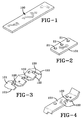
- a portion of a first strip 100 of metallic material commonly used to form blades for tire curing molds is shown.
- the resultant blades are stamped or punched out from the strip 100 and take various shapes as shown in Figs. 2 to 4.
- the blades may have any number of slots 120 or cuts 121 to form the various projections 122.
- the blades may be wavy as shown in Fig. 3 or have bends at their extremities (see Fig. 4).
- a second strip 200 of metallic material commonly used to form blades for tire curing molds is stamped or punched to form a second set of blade portions out from the strip 200 which may take various shapes as shown in Figs. 6 to 10.
- This second strip 200 of metallic material may have the same thickness as the first strip 100, a somewhat higher or smaller thickness. Usually the thickness of the first strip 100 ranges between 0.3 and 1 mm and the thickness of the second strip 200 between 0.3 and 0.8 mm.
- the metallic material of the second strip 200 may be the same as the one of the first strip 100.
- Preferred metallic material is steel because of its low cost. Further materials of interest are aluminum, nickel alloy, and titanium. Combinations of carbon steel constituting the first strip 100 with titanium or other metals containing steel alloys constituting the second strip 200 would allow a great flexibility in the choice of the blade portion thicknesses.
- the main blade portion 101 made out of the first strip 100 is usually at least partly anchored in the mold by holes 21 (see Fig. 2). This anchoring must be sufficient to insure that the composite blades do not pull out when the tread is extracted from the tire curing mold.
- the blade portion 201 made out of the second strip 200 is or is not anchored in the mold, depending on the design of the blade.
- the second blade portions 201 made out of the second strip 200 may take the shape of a rectangle (Fig. 6), parallelogram (Fig. 7), triangle (Fig. 9), trapezoid (Fig. 10) and may basically have any geometrical shape which is considered by a man skilled in the art to confer favorable properties to the tire tread. They may be flat as shown in Figs. 6 and 7, or they may be given a curved or wavy shape as shown in Fig. 8, depending on the fact that they will be assembled to a corresponding flat, curved or wavy main portion obtained out of the first strip 100. Alternatively the main portion 101 and the second portion 201 may be given at first a flat shape and after assembly stamped in order to obtain the desired wavy, sinusoidal or crimped or similar shape.
- the main and second blade portions 101, 201 are affixed together. This may be done by gluing using a high temperature epoxy adhesive or a high temperature cement. Another possibility is to subject the assembled portions to a combined compression and heat treatment. A still further possibility is to braze or solder the two portions. The presently preferred way is to weld the different portions together along their lateral adjacent sides, or at multiple points called "spot welding".
- the composite blades 300-312 may be fabricated at low cost in a great variety of shapes.
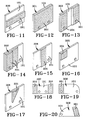
- Figs. 11 through 23 illustrate a few of these exemplary shapes, featuring different depths, widths and lengths.
- Fig. 11 shows a blade 300 providing a sipe having a greater width in its radially middle portion
- Fig. 12 shows a blade 301 having substantially a width double to the one offered by single metallic strips 100 or 200.
- Figs. 13, 14 and 15 show blades 302, 303, 304 providing sipes with laterally stepped off widths, allowing to tailor the elastomeric block stiffness to the requirements; such sipes influence locally transverse deformation of the blocks they are included in.
- Fig. 11 shows a blade 300 providing a sipe having a greater width in its radially middle portion
- Fig. 12 shows a blade 301 having substantially a width double to the one offered by single metallic strips 100 or 200.
- Figs. 13, 14 and 15 show blades 302, 303,
- FIG. 16 shows a blade 305 providing a sipe having on part of its lateral length and on part of its radially inner portion, a higher width.
- Fig. 17 shows a blade 306 producing a sipe having on part of its length a higher width, which length decreases towards the tread surface.
- Fig. 18 shows a blade 307 providing a sipe having on both sides a higher width and a depth decreasing from both sides towards the center.
- Fig. 19 shows a blade 308 providing a sipe having a first side a higher width and a depth decreasing towards the second side.
- Fig. 20 shows a blade 309 providing a sipe having a lateral length decreasing radially towards the tread bottom and a higher sipe width portion with a width and length remaining constant.
- the blades 310, 311 obtained according to the method of the invention may include the steps of bending.
- the bending step may take place before or after assembly of the different blade portions.
- the blades may further be crimped, notching or perforated before or after assembly.
- a blade 312 is shown where only part of the two metal sheets 101 and 201 overlap.
- the sheets 101 and 201 can have the same height or different heights.
- a block 241 is defined by laterally and circumferentially extending grooves 242, wherefrom only one kind can be represented in this cross-section.
- the block 241 includes sipe 245 which has in the case of the drawing throughout its height, substantially uniform thickness.
- the sipe 245 shows a protrusion 243 on one side and a recess 247 on the other.
- Such sipe 245 is easily obtained according to the inventive method by assembling to the radially outer part of a first side of a main portion 101 as shown in Fig. 2, a second blade portion 201 as shown in Fig. 6; a further similar second blade portion 201, as shown in Fig. 6 is assembled to the radially inner part of main portion 101.
- the protrusion 243 located on one side of the sipe advances towards recess 247 on the other side of the sipe, until it is in contact with such. Once in contact, protrusion 243 opposes any further deformation of the block 245. Opposite deformation does not result in such interlocking and the two adjacent sipe sidewalls may slide along each other as far as allowed by the rigidity of the rubbery material and the forces applied thereto. It appears that such sipe is directional. It appears further that such interlocking stops when the tire is worn down to the protrusion 243. At that time the stiffness of the block has increased and a limiting of flexing is no more desired.
- a block 251 is defined by laterally and circumferentially extending grooves 252.
- the block includes sipe 255 which has in the case of the drawing throughout its height, substantially uniform thickness. However, slightly above half-height, the sipe shows a protrusion 254 on one side and a recess 253 on the other.
- Such sipe is easily obtained according to the inventive method by assembling to a main portion 101 as shown in Fig. 2, two blade portion as shown in Fig.
- the loss due to wear of the non-directional interlocking (Fig. 24) or the change from non-directional to directional of the interlocking (Fig. 25) may be controlled by giving the recess 247, 253 and similarly the protrusion 243, 254 a small inclination. This can easily be implemented by assembling second blade portions 201, as shown in Fig. 7 to the main portion 101 of the composite blade 300-312.
Landscapes
- Engineering & Computer Science (AREA)
- Mechanical Engineering (AREA)
- Moulds For Moulding Plastics Or The Like (AREA)
- Heating, Cooling, Or Curing Plastics Or The Like In General (AREA)
Applications Claiming Priority (2)
| Application Number | Priority Date | Filing Date | Title |
|---|---|---|---|
| US815754 | 2001-03-23 | ||
| US09/815,754 US20020134202A1 (en) | 2001-03-23 | 2001-03-23 | Composite blade |
Publications (3)
| Publication Number | Publication Date |
|---|---|
| EP1243390A2 true EP1243390A2 (de) | 2002-09-25 |
| EP1243390A3 EP1243390A3 (de) | 2004-01-02 |
| EP1243390B1 EP1243390B1 (de) | 2006-08-02 |
Family
ID=25218749
Family Applications (1)
| Application Number | Title | Priority Date | Filing Date |
|---|---|---|---|
| EP02100259A Expired - Lifetime EP1243390B1 (de) | 2001-03-23 | 2002-03-15 | Verbundblatt für ein Reifenvulkanisierformwerkzeug |
Country Status (5)
| Country | Link |
|---|---|
| US (2) | US20020134202A1 (de) |
| EP (1) | EP1243390B1 (de) |
| JP (1) | JP2002355822A (de) |
| BR (1) | BR0200777A (de) |
| DE (1) | DE60213498T2 (de) |
Cited By (9)
| Publication number | Priority date | Publication date | Assignee | Title |
|---|---|---|---|---|
| US7143799B2 (en) * | 2003-11-20 | 2006-12-05 | The Goodyear Tire & Rubber Company | Three-dimensional sipes for treads |
| EP1935601A1 (de) * | 2006-12-21 | 2008-06-25 | The Goodyear Tire & Rubber Company | Flexible Formvorrichtung zur Herstellung einer Senknut in einem Reifenprofil |
| EP1938956A1 (de) * | 2006-12-21 | 2008-07-02 | The Goodyear Tire & Rubber Company | Flexible Formvorrichtung zur Herstellung einer Senknut oder einer Oberflächenverbindungsstange in einem Reifenprofil |
| RU2469858C1 (ru) * | 2008-10-03 | 2012-12-20 | Компани Женераль Дез Этаблиссман Мишлен | Волнообразный прогрессивный формообразующий элемент для шины |
| WO2016054278A1 (en) * | 2014-09-30 | 2016-04-07 | Compagnie Generale Des Etablissements Michelin | A tire tread comprising variable thickness sipes with multiple areas of reduced thickness |
| EP3219479A1 (de) * | 2016-03-17 | 2017-09-20 | Herbert Maschinenbau GmbH & Co. KG | Matrize für eine reifenform, reifenform und verfahren zur herstellung |
| FR3053919A1 (fr) * | 2016-07-18 | 2018-01-19 | Compagnie Generale Des Etablissements Michelin | Lamelle hybride de garniture d’un moule pour pneumatique |
| EP3871905A1 (de) * | 2020-02-28 | 2021-09-01 | Bridgestone Americas Tire Operations, LLC | Verstärktes reifenlamellenblatt |
| US11338618B2 (en) | 2015-09-30 | 2022-05-24 | Compagnie Generale Des Etablissements Michelin | Egg crate sidewall features for sipes |
Families Citing this family (35)
| Publication number | Priority date | Publication date | Assignee | Title |
|---|---|---|---|---|
| FR2871735B1 (fr) * | 2004-06-16 | 2006-08-04 | Michelin Soc Tech | Bande de roulement ayant des incisions zigzag et lames pour le moulage de telles incisions |
| US7468153B2 (en) | 2004-12-30 | 2008-12-23 | The Goodyear Tire & Rubber Co. | Degradable blading for tire curing molds |
| US7360568B2 (en) * | 2005-01-27 | 2008-04-22 | Bridgestone Firestone North American Tire, Llc | Tire having narrowing sipes |
| DE102005030176A1 (de) * | 2005-06-29 | 2007-01-04 | Continental Aktiengesellschaft | Form zur Ausformung der Profilierung eines Fahrzeugluftreifens |
| JP4751164B2 (ja) * | 2005-10-06 | 2011-08-17 | 株式会社ブリヂストン | 空気入りタイヤ |
| US8277589B2 (en) * | 2006-11-29 | 2012-10-02 | Michelin Recherche Et Technique S.A. | Method of retreading a tire |
| US7575424B2 (en) * | 2006-12-21 | 2009-08-18 | The Goodyear Tire & Rubber Company | Flexible molding device for manufacturing a sunken groove in a tire tread |
| US7566213B2 (en) * | 2006-12-21 | 2009-07-28 | The Goodyear Tire & Rubber Company | Flexible enrobed molding device for manufacturing a sunken groove in a tire tread |
| US7507078B2 (en) * | 2006-12-21 | 2009-03-24 | The Goodyear Tire & Rubber Company | Flexible molding device for molding a sunk groove, a sunk blade, and a large keyhole sipe in tire tread |
| JP4318148B2 (ja) * | 2007-05-29 | 2009-08-19 | 東洋ゴム工業株式会社 | 空気入りタイヤ |
| JP4404922B2 (ja) * | 2007-08-24 | 2010-01-27 | 東洋ゴム工業株式会社 | 空気入りタイヤ |
| JP5261783B2 (ja) * | 2007-09-26 | 2013-08-14 | 東洋ゴム工業株式会社 | 空気入りタイヤ |
| JP4446077B2 (ja) * | 2007-12-28 | 2010-04-07 | 東洋ゴム工業株式会社 | 空気入りタイヤ |
| JP2009248819A (ja) * | 2008-04-08 | 2009-10-29 | Toyo Tire & Rubber Co Ltd | 空気入りタイヤ |
| JP5270407B2 (ja) * | 2009-03-09 | 2013-08-21 | 東洋ゴム工業株式会社 | 空気入りタイヤ |
| JP4394161B1 (ja) * | 2009-04-17 | 2010-01-06 | 横浜ゴム株式会社 | 空気入りタイヤ |
| JP5562727B2 (ja) * | 2010-06-01 | 2014-07-30 | 東洋ゴム工業株式会社 | 空気入りタイヤ |
| JP5797452B2 (ja) * | 2011-05-16 | 2015-10-21 | 東洋ゴム工業株式会社 | サイプブレード及びタイヤ製造方法 |
| WO2013115810A1 (en) * | 2012-01-31 | 2013-08-08 | Michelin Recherche Et Technique S.A. | Projecting features molded within submerged tread voids |
| FR3000424B1 (fr) | 2012-12-28 | 2015-05-15 | Michelin & Cie | Element de moule comportant des moyens de decoupe pour le moulage et la vulcanisation d'une bande de roulement d'un pneumatique |
| JP5957405B2 (ja) * | 2013-03-19 | 2016-07-27 | 住友ゴム工業株式会社 | 空気入りタイヤ |
| JP5690375B2 (ja) * | 2013-06-05 | 2015-03-25 | 株式会社ブリヂストン | タイヤ |
| JP6472023B2 (ja) * | 2014-12-25 | 2019-02-20 | Toyo Tire株式会社 | 空気入りタイヤ及びその成形型 |
| WO2017058226A1 (en) | 2015-09-30 | 2017-04-06 | Compagnie Generale Des Etablissements Michelin | Variable thickness sipes |
| FR3045452B1 (fr) * | 2015-12-18 | 2018-02-16 | Compagnie Generale Des Etablissements Michelin | Lamelles de garniture pour moule de pneumatique et procede de fabrication associe |
| KR101782621B1 (ko) * | 2016-06-28 | 2017-09-27 | 넥센타이어 주식회사 | 타이어 |
| FR3053920B1 (fr) * | 2016-07-18 | 2018-07-13 | Compagnie Generale Des Etablissements Michelin | Insert texture pour garniture d’un moule destine a la vulcanisation d’un pneumatique |
| EP3519174B1 (de) * | 2016-09-29 | 2020-12-16 | Compagnie Générale des Etablissements Michelin | Formelement zur herstellung einer geräuschreduzierenden lauffläche |
| JP6885176B2 (ja) * | 2017-04-18 | 2021-06-09 | 住友ゴム工業株式会社 | タイヤ |
| JP6904783B2 (ja) * | 2017-05-15 | 2021-07-21 | Toyo Tire株式会社 | タイヤ加硫金型及びタイヤ加硫金型の製造方法 |
| FR3081364B1 (fr) * | 2018-05-25 | 2020-06-12 | Compagnie Generale Des Etablissements Michelin | Ensemble d'elements moulants |
| EP3941729B1 (de) * | 2019-03-20 | 2023-08-30 | Bridgestone Americas Tire Operations, LLC | Gegenmassnahme gegen ungleichmässigen verschleiss und lärm |
| FR3097153B1 (fr) * | 2019-06-14 | 2022-09-16 | Michelin & Cie | Moule en deux parties pour la vulcanisation de pneumatiques |
| JP7578498B2 (ja) * | 2021-02-09 | 2024-11-06 | 株式会社ブリヂストン | サイプブレード及びタイヤ成型用金型並びにタイヤ製造方法 |
| ES2993001T3 (en) * | 2021-09-29 | 2024-12-20 | Ceat Ltd | Pneumatic tire with three-dimensional sipe |
Family Cites Families (20)
| Publication number | Priority date | Publication date | Assignee | Title |
|---|---|---|---|---|
| US2736924A (en) * | 1953-10-01 | 1956-03-06 | Morris Bean & Company | Bladed tire molds and method |
| FR1203290A (fr) * | 1959-07-01 | 1960-01-18 | Us Rubber Co | Perfectionnements apportés aux moules à pneumatiques |
| US3581535A (en) * | 1968-07-11 | 1971-06-01 | Goodyear Tire & Rubber | Method and apparatus for making blades |
| US3880020A (en) * | 1973-06-06 | 1975-04-29 | Goodyear Tire & Rubber | Making blades for tire curing molds |
| US4086966A (en) * | 1976-12-20 | 1978-05-02 | Caterpillar Tractor Co. | Composite ground engaging tool |
| FR2641501B1 (fr) * | 1989-01-10 | 1991-03-08 | Michelin & Cie | Bande de roulement pour pneumatique destine a des roulages hivernaux |
| JPH0390317A (ja) * | 1989-08-31 | 1991-04-16 | Ohtsu Tire & Rubber Co Ltd :The | サイプ付きブロックタイヤ成形用サイプ形成部材 |
| JP3145139B2 (ja) * | 1991-05-31 | 2001-03-12 | 東洋ゴム工業株式会社 | 空気入りタイヤ成形用サイプブレード |
| FR2683771B1 (fr) * | 1991-11-18 | 1994-01-07 | Michelin & Cie | Bande de roulement pourvue de rainures dont les parois sont munies d'incisions. |
| JP3291132B2 (ja) * | 1994-07-15 | 2002-06-10 | 株式会社ブリヂストン | タイヤ加硫用金型およびタイヤ加硫用金型に使用される金属製ブレードの製造方法 |
| JP3715008B2 (ja) * | 1995-11-17 | 2005-11-09 | 株式会社ブリヂストン | タイヤ加硫金型およびタイヤ加硫金型に使用されるサイプ・ブレードの製造方法 |
| FR2759626A1 (fr) * | 1997-02-19 | 1998-08-21 | Sedepro | Moule pour pneus |
| FR2762539A1 (fr) * | 1997-04-24 | 1998-10-30 | Michelin & Cie | Element moulant un motif dans une bande de roulement |
| AU3495597A (en) * | 1997-06-23 | 1999-01-04 | Goodyear Tire And Rubber Company, The | Tire mold reinforcement |
| JP4081177B2 (ja) * | 1997-07-07 | 2008-04-23 | 株式会社ブリヂストン | 空気入りタイヤ |
| CA2301126A1 (en) * | 1997-10-27 | 1999-05-06 | The Goodyear Tire & Rubber Company | Article and method for composite tire mold blades |
| US6264453B1 (en) * | 1997-10-27 | 2001-07-24 | The Goodyear Tire & Rubber Company | Article and method for composite tire mold blades |
| JP3822338B2 (ja) * | 1997-11-19 | 2006-09-20 | 株式会社ブリヂストン | 空気入りタイヤ |
| DE19804338C2 (de) * | 1998-02-05 | 2002-03-28 | Continental Ag | Fahrzeugluftreifen |
| JP2000255218A (ja) * | 1999-03-05 | 2000-09-19 | Bridgestone Corp | 空気入りタイヤ、タイヤ加硫モールド用ブレード及び空気入りタイヤの製造方法 |
-
2001
- 2001-03-23 US US09/815,754 patent/US20020134202A1/en not_active Abandoned
-
2002
- 2002-03-13 BR BR0200777-0A patent/BR0200777A/pt not_active Application Discontinuation
- 2002-03-15 DE DE60213498T patent/DE60213498T2/de not_active Expired - Lifetime
- 2002-03-15 EP EP02100259A patent/EP1243390B1/de not_active Expired - Lifetime
- 2002-03-25 JP JP2002083292A patent/JP2002355822A/ja active Pending
-
2003
- 2003-01-03 US US10/336,269 patent/US20030101851A1/en not_active Abandoned
Cited By (16)
| Publication number | Priority date | Publication date | Assignee | Title |
|---|---|---|---|---|
| US7143799B2 (en) * | 2003-11-20 | 2006-12-05 | The Goodyear Tire & Rubber Company | Three-dimensional sipes for treads |
| EP1935601A1 (de) * | 2006-12-21 | 2008-06-25 | The Goodyear Tire & Rubber Company | Flexible Formvorrichtung zur Herstellung einer Senknut in einem Reifenprofil |
| EP1938956A1 (de) * | 2006-12-21 | 2008-07-02 | The Goodyear Tire & Rubber Company | Flexible Formvorrichtung zur Herstellung einer Senknut oder einer Oberflächenverbindungsstange in einem Reifenprofil |
| US7544054B2 (en) | 2006-12-21 | 2009-06-09 | The Goodyear Tire & Rubber Company | Flexible molding device for manufacturing a sunken groove in a tire tread |
| US7544053B2 (en) | 2006-12-21 | 2009-06-09 | The Goodyear Tire And Rubber Company | Flexible molding device for manufacturing a sunken groove or surface tie bar in a tire tread |
| RU2469858C1 (ru) * | 2008-10-03 | 2012-12-20 | Компани Женераль Дез Этаблиссман Мишлен | Волнообразный прогрессивный формообразующий элемент для шины |
| CN106852135B (zh) * | 2014-09-30 | 2019-06-14 | 米其林集团总公司 | 包括具有多个厚度减小的区域的可变厚度胎纹沟槽的轮胎胎面 |
| CN106852135A (zh) * | 2014-09-30 | 2017-06-13 | 米其林集团总公司 | 包括具有多个厚度减小的区域的可变厚度胎纹沟槽的轮胎胎面 |
| WO2016054278A1 (en) * | 2014-09-30 | 2016-04-07 | Compagnie Generale Des Etablissements Michelin | A tire tread comprising variable thickness sipes with multiple areas of reduced thickness |
| US10773556B2 (en) | 2014-09-30 | 2020-09-15 | Compagnie Generale Des Etablissements Michelin | Tire tread comprising variable thickness sipes with multiple areas of reduced thickness |
| US11338618B2 (en) | 2015-09-30 | 2022-05-24 | Compagnie Generale Des Etablissements Michelin | Egg crate sidewall features for sipes |
| EP3219479A1 (de) * | 2016-03-17 | 2017-09-20 | Herbert Maschinenbau GmbH & Co. KG | Matrize für eine reifenform, reifenform und verfahren zur herstellung |
| FR3053919A1 (fr) * | 2016-07-18 | 2018-01-19 | Compagnie Generale Des Etablissements Michelin | Lamelle hybride de garniture d’un moule pour pneumatique |
| WO2018015630A1 (fr) * | 2016-07-18 | 2018-01-25 | Compagnie Generale Des Etablissements Michelin | Lamelle hybride de garniture d'un moule pour pneumatique |
| CN109476046A (zh) * | 2016-07-18 | 2019-03-15 | 米其林集团总公司 | 用于轮胎的模具内镶物的混合薄板 |
| EP3871905A1 (de) * | 2020-02-28 | 2021-09-01 | Bridgestone Americas Tire Operations, LLC | Verstärktes reifenlamellenblatt |
Also Published As
| Publication number | Publication date |
|---|---|
| DE60213498T2 (de) | 2007-10-18 |
| EP1243390A3 (de) | 2004-01-02 |
| US20020134202A1 (en) | 2002-09-26 |
| EP1243390B1 (de) | 2006-08-02 |
| JP2002355822A (ja) | 2002-12-10 |
| BR0200777A (pt) | 2003-01-07 |
| DE60213498D1 (de) | 2006-09-14 |
| US20030101851A1 (en) | 2003-06-05 |
Similar Documents
| Publication | Publication Date | Title |
|---|---|---|
| EP1243390B1 (de) | Verbundblatt für ein Reifenvulkanisierformwerkzeug | |
| US6264453B1 (en) | Article and method for composite tire mold blades | |
| US6431331B1 (en) | Brake plate and method and apparatus for manufacturing same | |
| US6910255B2 (en) | Brake plate and method and apparatus for manufacturing same | |
| EP1648645B1 (de) | Sägenblatt | |
| EP0541723B1 (de) | Rasiersystem | |
| JP2002355822A5 (de) | ||
| JP2006518613A (ja) | レザーブレードの製造方法 | |
| JP2008532774A (ja) | 折曲げ制御用変位部を有するシート材料を形成する方法およびツール処理装置 | |
| WO1999021701A1 (en) | Article and method for composite tire mold blades | |
| KR101414100B1 (ko) | 타이어 성형금형 | |
| JP3237868B2 (ja) | 往復式電気かみそりの内刃の製法 | |
| JP3673152B2 (ja) | 被固定部材、整流子形成板材、及びそれらの製造方法 | |
| AU2004295163B2 (en) | Structural beam with openings | |
| CN100448604C (zh) | 电动剃须刀内刀的制造方法 | |
| US4531276A (en) | Method of making a drum brake shoe and lining assembly | |
| US4306347A (en) | Method for manufacturing slide fastener elements | |
| JP4570209B2 (ja) | Cvtベルト用エレメントとその製造方法 | |
| JPH0758096B2 (ja) | 半割軸受の製造方法 | |
| CN111906823B (zh) | 形成切割刀片或防护件的齿的方法 | |
| CN212419472U (zh) | 模具 | |
| JP3681654B2 (ja) | タイヤ金型用サイプブレードの製造方法 | |
| JP3183274B2 (ja) | アルミニウム合金製ローター素材の鍛造方法 | |
| KR100558593B1 (ko) | 정류자 제조 방법 및 이에 의해 제조된 정류자 | |
| JP2003145545A (ja) | タイヤ金型用サイプブレードの製造方法 |
Legal Events
| Date | Code | Title | Description |
|---|---|---|---|
| PUAI | Public reference made under article 153(3) epc to a published international application that has entered the european phase |
Free format text: ORIGINAL CODE: 0009012 |
|
| AK | Designated contracting states |
Kind code of ref document: A2 Designated state(s): AT BE CH CY DE DK ES FI FR GB GR IE IT LI LU MC NL PT SE TR |
|
| AX | Request for extension of the european patent |
Free format text: AL;LT;LV;MK;RO;SI |
|
| PUAL | Search report despatched |
Free format text: ORIGINAL CODE: 0009013 |
|
| AK | Designated contracting states |
Kind code of ref document: A3 Designated state(s): AT BE CH CY DE DK ES FI FR GB GR IE IT LI LU MC NL PT SE TR |
|
| AX | Request for extension of the european patent |
Extension state: AL LT LV MK RO SI |
|
| RIC1 | Information provided on ipc code assigned before grant |
Ipc: 7B 29L 30:00 Z Ipc: 7B 29C 33/38 A Ipc: 7B 29D 30/06 B |
|
| 17P | Request for examination filed |
Effective date: 20040702 |
|
| AKX | Designation fees paid |
Designated state(s): DE FR GB |
|
| 17Q | First examination report despatched |
Effective date: 20040824 |
|
| GRAP | Despatch of communication of intention to grant a patent |
Free format text: ORIGINAL CODE: EPIDOSNIGR1 |
|
| GRAS | Grant fee paid |
Free format text: ORIGINAL CODE: EPIDOSNIGR3 |
|
| GRAA | (expected) grant |
Free format text: ORIGINAL CODE: 0009210 |
|
| AK | Designated contracting states |
Kind code of ref document: B1 Designated state(s): DE FR GB |
|
| REG | Reference to a national code |
Ref country code: GB Ref legal event code: FG4D |
|
| REF | Corresponds to: |
Ref document number: 60213498 Country of ref document: DE Date of ref document: 20060914 Kind code of ref document: P |
|
| ET | Fr: translation filed | ||
| PLBE | No opposition filed within time limit |
Free format text: ORIGINAL CODE: 0009261 |
|
| STAA | Information on the status of an ep patent application or granted ep patent |
Free format text: STATUS: NO OPPOSITION FILED WITHIN TIME LIMIT |
|
| 26N | No opposition filed |
Effective date: 20070503 |
|
| PGFP | Annual fee paid to national office [announced via postgrant information from national office to epo] |
Ref country code: GB Payment date: 20080211 Year of fee payment: 7 |
|
| GBPC | Gb: european patent ceased through non-payment of renewal fee |
Effective date: 20090315 |
|
| PG25 | Lapsed in a contracting state [announced via postgrant information from national office to epo] |
Ref country code: GB Free format text: LAPSE BECAUSE OF NON-PAYMENT OF DUE FEES Effective date: 20090315 |
|
| REG | Reference to a national code |
Ref country code: FR Ref legal event code: PLFP Year of fee payment: 15 |
|
| REG | Reference to a national code |
Ref country code: FR Ref legal event code: PLFP Year of fee payment: 16 |
|
| PGFP | Annual fee paid to national office [announced via postgrant information from national office to epo] |
Ref country code: FR Payment date: 20170222 Year of fee payment: 16 |
|
| PGFP | Annual fee paid to national office [announced via postgrant information from national office to epo] |
Ref country code: DE Payment date: 20170331 Year of fee payment: 16 |
|
| REG | Reference to a national code |
Ref country code: DE Ref legal event code: R119 Ref document number: 60213498 Country of ref document: DE |
|
| PG25 | Lapsed in a contracting state [announced via postgrant information from national office to epo] |
Ref country code: DE Free format text: LAPSE BECAUSE OF NON-PAYMENT OF DUE FEES Effective date: 20181002 |
|
| PG25 | Lapsed in a contracting state [announced via postgrant information from national office to epo] |
Ref country code: FR Free format text: LAPSE BECAUSE OF NON-PAYMENT OF DUE FEES Effective date: 20180331 |