EP1243706B1 - Abstützbein mit einem Verschleißteil - Google Patents
Abstützbein mit einem Verschleißteil Download PDFInfo
- Publication number
- EP1243706B1 EP1243706B1 EP02006413A EP02006413A EP1243706B1 EP 1243706 B1 EP1243706 B1 EP 1243706B1 EP 02006413 A EP02006413 A EP 02006413A EP 02006413 A EP02006413 A EP 02006413A EP 1243706 B1 EP1243706 B1 EP 1243706B1
- Authority
- EP
- European Patent Office
- Prior art keywords
- wear pad
- stabilizer leg
- outer part
- wear
- leg according
- Prior art date
- Legal status (The legal status is an assumption and is not a legal conclusion. Google has not performed a legal analysis and makes no representation as to the accuracy of the status listed.)
- Expired - Lifetime
Links
- 239000003381 stabilizer Substances 0.000 title claims abstract description 26
- 239000000463 material Substances 0.000 claims abstract description 16
- 239000007779 soft material Substances 0.000 claims abstract description 6
- 230000000087 stabilizing effect Effects 0.000 claims description 19
- 239000004677 Nylon Substances 0.000 claims description 7
- 229920001778 nylon Polymers 0.000 claims description 7
- 239000004033 plastic Substances 0.000 claims description 6
- 229920003023 plastic Polymers 0.000 claims description 6
- 229910000831 Steel Inorganic materials 0.000 claims description 3
- 239000002184 metal Substances 0.000 claims description 3
- 239000010959 steel Substances 0.000 claims description 3
- 230000003014 reinforcing effect Effects 0.000 description 3
- 229920002292 Nylon 6 Polymers 0.000 description 1
- 230000000694 effects Effects 0.000 description 1
- 239000000314 lubricant Substances 0.000 description 1
- 230000001050 lubricating effect Effects 0.000 description 1
Images

Classifications
-
- E—FIXED CONSTRUCTIONS
- E02—HYDRAULIC ENGINEERING; FOUNDATIONS; SOIL SHIFTING
- E02F—DREDGING; SOIL-SHIFTING
- E02F9/00—Component parts of dredgers or soil-shifting machines, not restricted to one of the kinds covered by groups E02F3/00 - E02F7/00
- E02F9/08—Superstructures; Supports for superstructures
- E02F9/085—Ground-engaging fitting for supporting the machines while working, e.g. outriggers, legs
Definitions
- This invention relates to a wear pad for a stabilizer leg for a vehicle and more particularly, but not exclusively, to stabilizing frames in or for excavators of the kind comprising an excavator assembly adapted for mounting on the stabilizing frame which is securable to the rear of a tractor or like vehicle wherein the excavator assembly comprises a boom pivotally mounted at its lower end for movement up and down in a vertical plane and carrying at its outer end a pivotally mounted dipper arm upon which is mounted an excavating tool such as a bucket, and wherein the boom is mounted also for traversing movement about a vertical axis so as to be capable of being swung from side-to-side of the centre line of the tractor, the frame having at each side an extensible leg member whereby, for example, when an excavator comprising such an excavator assembly, frame and tractor is operating upon uneven ground or soft ground or upon an inclination, the legs may be extended as required to ensure a firm support for the stabilizing frame.
- EP-A-0867566 discloses a stabilizer leg comprising telescopic inner and outer parts and a wear pad adjustably engaged with one of the parts to permit adjustment of clearance between the wear pad and an opposed surface of the other of the said parts.
- An object of the invention is to provide a new and improved wear pad for a stabilizer leg and a new and improved stabilizing frame in or for an excavator of the kind above specified.
- a stabilizer leg comprising an upper outer part having telescopically slidable therein a lower inner part having a ground engagable portion and a wear pad being adjustably engaged with the outer of said parts to permit adjustment of clearance between the wear pad and an opposed surface of the other said parts, the wear pad being threadedly engaged with the outer part whereby rotation of the wear pad relative to the outer part causes relative movement between said wear pad and the outer part in a direction transverse to a direction in which said parts telescope, the wear pad comprising a wear surface and engagement means, characterised in that the wear pad has a first part comprising a first, relatively soft material to provide the wear surface and a second part comprising a second, relatively hard material, wherein the engagement means comprises an external thread provided on the second part, the second part having a generally cylindrical surface and said cylindrical surface being provided with the external thread, the external thread being in threaded engagement with an internally threaded part of said outer part and wherein the first part is rele
- the first material may comprise a plastics material.
- the plastics material may comprise nylon.
- the nylon may be provided with a lubricant.
- the second material may comprise metal, preferably steel.
- the first part and second part may be provided with interengaging connection means.
- the wear pad may be provided with a socket to receive a tool whereby the wear pad may be rotated.
- the socket may be a square or other non-circular section recess.
- the socket may be provided in an end part of the second part.
- Means may be provided to provide a frictional resistance to said relative threaded rotation.
- One of said threaded parts preferably the wear pad, may be provided with an insert for providing a frictional resistance to relative threaded rotation between the wear pad and said outer part.
- the outer part may be provided with a boss and the boss may be provided with said internal thread.
- the outer part may be provided with a further wear pad on a side thereof opposite to said adjustable wear pad.
- the stabilizer leg may be rectangular in section and two adjacent sides of the outer part may be provided with an adjustable wear pad.
- a stabilizing frame in or for an excavator or the kind specified, wherein the frame has at each of two opposite sides a stabilizer leg according to the first aspect of the invention.
- the stabilizer legs of the stabilizing frame may be interconnected by cross rail means to provide the stabilizing frame.
- the cross rail means may comprise a pair of cross rails, one disposed adjacent a lower part of each outer part and the other provided thereabove but downwardly from a top end of the outer part.
- the cross rail means may provide guide ways for side shifting movement of a king post assembly for carrying an excavator assembly.
- two adjacent sides of the outer part may be provided with an adjustable wear pad and the two opposite sides of the outer part may be provided with a further wear pad which may be fixed or adjustable.
- the provision of the wear pads ensures that the inner part telescopes relative to the outer part with a desired clearance between the inner part and the wear pads.
- the desired clearance between the inner part and the wear pads may be maintained simply by rotating one or each of the wear pads, as necessary, by engagement of a suitable tool within the above mentioned recess to take up the desired wear.
- the upper part of the leg may be adapted to be fixed relative to a vehicle.
- Two stabilizer legs may be adapted to be provided on opposite sides of a vehicle.
- a stabilizing frame in or for an excavator of the kind specified wherein the frame has at each of two opposite sides a stabilizer leg according to the first aspect of the invention.
- the stabilizer legs are inter-connected by cross rail means to provide the stabilizing frame.
- the cross rail means may comprise a pair of cross rails one disposed adjacent a lower part of each outer part and the other provided thereabove but spaced downwardly from a top end of the outer part.
- the cross rail means may provide guide ways for side shifting movement of a king post assembly which may carry an excavator assembly.
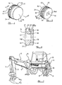
- a rear elevation of a stabilizing frame of an excavator is illustrated generally at 10 and comprises a pair of upper, outer, housing parts 11 inter-connected by a lower cross rail 12 disposed adjacent a lower end 13 of each housing 11 and an upper cross rail 14 disposed above the rail 12 and downwardly from an upper end 15 of the housing 11.
- the rails 12, 14 provide a guide means for a king post assembly 16 on which a conventional back-hoe type of excavator is mounted as best shown in Figure 7 .
- the back-hoe excavator is mounted by the stabilizing frame 10 on the rear of a excavator vehicle 1 and comprises a bucket 2 pivotally mounted for movement in a vertical plane on a dipper arm 3 which in turn is pivotally mounted, again for movement in a vertical plane, on a boom 4.
- the inner end of the boom 4 is pivotally mounted, for movement in a horizontal and vertical plane, on the stabilizing frame 10 by means of the king post 16.
- Hydraulic rams 5 are provided to effect the various pivotal movements of the bucket and the dipper arm relative to the dipper arm and the boom respectively.
- each housing part 11 is made as a U-shaped pressing 20 which is closed by a plate 21 welded across the open mouth thereof and extending longitudinally thereof.
- a reinforcing bracket, also of U-shaped cross-section is welded around the housing adjacent its lower end as shown at 22 and a pair of bosses 23 are welded in apertures 24 provided in the housing part 20 and the reinforcing bracket 22 so as to provide a pair of wear pad housings.
- the bosses 23 providing the wear pad housings have an internally threaded passage 25.
- the housing part 20 is provided with an aperture 26 whilst the reinforcing bracket 22 is not provided with an aperture at this position.
- a fixed wear pad of a suitable material in the present example a suitable self lubricated nylon, is shown at 27 and comprises a spigot part 28 received within the aperture 26 and an enlarged head part 29 having an inwardly facing surface 30 which is adapted to provide a wear surface for an inner, lower leg, part 31 of the stabilizer.
- the wear pad 32 comprises a first part 33 and a second part 34.
- the first part 33 is generally cylindrical in appearance, with an end face 35 thereof providing an operative wear surface.
- the first part 33 preferably comprises a relatively soft material, such as a plastics material such as nylon and preferably a self lubricating nylon.
- the second part 34 comprises a cylindrical part 36 having a generally cylindrical outer surface provided with an external thread 37.
- the second part 34 is preferably made of a relatively hard material, such as a metal and preferably steel.
- the second part 34 is provided with a projecting part 38 which in the present example is generally cylindrical and of a smaller diameter than the cylindrical part 36. At an outer end thereof the projecting part 38 is provided with a lip 39. The projecting part 38 is received in a corresponding blind recess 40 provided in the first part 33.
- the recess 40 is provided with an inwardly directed flange 40 a at its periphery. The dimensions of the projecting part 38 and lip 39 and recess 40 and flange 40 a are such that they interengage in a snap-fit fashion such that the first part 33 and second part 34 are firmly connected.
- the first part 33 comprises a desired relatively soft material such as nylon
- the first part 33 can be resiliently deformed sufficiently to pass the flange 40 a over the lip 39.
- the adjustable wear pad 32 has a socket 41 of a suitable non-circular shape, in the present example of square cross section, for receiving a suitable tool such as a standard socket set bar, whereby the adjustable wear pad 32 may be rotated relative to the boss 23 and so as to move the operative wear surface 35 of the wear pad 32 transversely of the direction of telescopic movement between the inner and outer leg parts relatively to an opposed surface of inner leg part 31.
- the socket 41 extends through the second part 34 from an end face 34a, but may of course comprise a blind recess if desired.
- the adjustable wear pad 32 is provided with a stiff thread facility whereby resistance to rotation is provided and in particular inadvertent rotation in service is resisted. In the present example, this is provided by means of a generally radially disposed plug 42 received in a recess 43 of cylindrical configuration.
- the plug 42 is peripherally made of a suitable synthetic plastics material, in this case nylon 6, and is preferably provided with a plain operative surface 44 and is dimensioned so as to be an interference fit with the internal thread of the boss 23, thus providing a resistance to relative rotation of the wear pad 32 and the boss 23.
- the external thread 37 engages an internal thread of the boss 23.
- the or each adjustable wear pad 32 is rotated until the inner leg part 31 is clamped against the opposed fixed wear pad and then they are backed off an appropriate amount, in the present example 1 ⁇ 4 of a turn, the thread being of 3mm pitch.
- Such adjustment is quick and simple.
- the wear pad 32 can be rotated to maintain the desired clearance between the inner and outer leg parts by engagement of a tool with a socket 41.
- the first part 33 of the wear pad 32 has worn to such an extent that it becomes desirable to replace the wear pad 32, it will be apparent that this may be achieved simply by unscrewing the wear pad 32 from the boss 23, removing the old first part 33 and snapping on a replacement new part 33. The wear pad 32 may then be screwed back into the boss and adjusted as described above.
- the wear pad 32 comprises a relatively hard second part 34 provided with a thread 37 to engage the boss 23, the risk of foreign materials being introduced between the housing part 11 and the inner leg part 31 as a result of deformation of the wear pad 32 is reduced. It is known that where a wear pad 32 entirely comprises a softer material, deformation of the wear pad 32, particularly as a result of the plug 42, can lead to clearance developing between the wear pad 32 and the internal thread of the boss 23 permitting the entry of foreign bodies into the housing part 11.
Landscapes
- Engineering & Computer Science (AREA)
- Mining & Mineral Resources (AREA)
- Civil Engineering (AREA)
- General Engineering & Computer Science (AREA)
- Structural Engineering (AREA)
- Walking Sticks, Umbrellas, And Fans (AREA)
- Polishing Bodies And Polishing Tools (AREA)
- Legs For Furniture In General (AREA)
- Earth Drilling (AREA)
- Adjustment Of The Magnetic Head Position Track Following On Tapes (AREA)
- Magnetic Heads (AREA)
- Component Parts Of Construction Machinery (AREA)
- Orthopedics, Nursing, And Contraception (AREA)
- Footwear And Its Accessory, Manufacturing Method And Apparatuses (AREA)
- Finger-Pressure Massage (AREA)
- Adornments (AREA)
Claims (14)
- Stabilisatorstütze, die Folgendes umfasst: ein oberes äußeres Teil (11), in dem ein unteres inneres Teil (31) teleskopisch gleiten kann, das einen Abschnitt für den Kontakt mit dem Boden sowie einen Verschleißschutz (32) aufweist, der mit dem äußeren der Teile (11, 31) einstellbar in Eingriff steht, um eine Einstellung des Abstands zwischen dem Verschleißschutz (32) und einer gegenüberliegenden Fläche des anderen der Teile (11, 31) zu ermöglichen, wobei der Verschleißschutz (32) mittels Gewinde mit dem äußeren Teil (11) in Eingriff steht, wodurch eine Drehung des Verschleißschutzes (32) im Verhältnis zu dem äußeren Teil (11) eine relative Bewegung zwischen dem Verschleißschutz (32) und dem äußeren Teil (11) in einer Richtung quer zu einer Richtung verursacht, in der sich die Teile (11, 31) teleskopisch bewegen, wobei der Verschleißschutz (32) eine Verschleißfläche (35) und ein Eingriffsmittel umfasst, dadurch gekennzeichnet, dass der Verschleißschutz Folgendes aufweist: ein erstes Teil (33), das ein erstes relativ weiches Material umfasst, um die Verschleißfläche (35) bereitzustellen, und ein zweites Teil (34), das ein zweites relativ hartes Material umfasst, wobei das Eingriffsmittel ein Außengewinde (37) umfasst, das an dem zweiten Teil (34) bereitgestellt ist, wobei das zweite Teil (34) eine im Allgemeinen zylindrische Fläche aufweist und die zylindrische Fläche mit dem Außengewinde (37) versehen ist, wobei das Außengewinde mittels Gewinde mit einem inneren mit Gewinde versehenen Teil des äußeren Teils (11) in Eingriff steht und wobei das erste Teil (33) lösbar an dem zweiten Teil (34) angebracht werden kann.
- Stabilisatorstütze nach Anspruch 1, wobei das erste relativ weiche Material ein Kunststoffmaterial umfasst.
- Stabilisatorstütze nach Anspruch 2, wobei das Kunststoffmaterial Nylon umfasst.
- Stabilisatorstütze nach einem der Ansprüche 1 bis 3, wobei das zweite Material Metall, wie zum Beispiel Stahl, umfasst.
- Stabilisatorstütze nach einem der vorhergehenden Ansprüche, wobei das zweite Teil (34) mit einem Einsatz (42) versehen ist, um einen Reibungswiderstand gegen eine relative Gewindedrehung zwischen dem Verschleißschutz (32) und dem mit Innengewinde versehenen Teil (23) bereitzustellen.
- Stabilisatorstütze nach einem der vorhergehenden Ansprüche, wobei das erste Teil (33) und das zweite Teil (34) mit ineinander eingreifenden Verbindungsmitteln (38, 40) versehen sind.
- Stabilisatorstütze nach einem der vorhergehenden Ansprüche, wobei der Verschleißschutz (32) mit einer Öffnung (41) versehen ist, um ein Werkzeug aufzunehmen, wodurch der Verschleißschutz (32) gedreht werden kann, wobei die Öffnung (41) in einem Endteil des zweiten Teils (34) vorgesehen ist.
- Stabilisatorstütze nach einem der vorhergehenden Ansprüche, wobei das äußere Teil (11) mit einem Vorsprung (23) versehen ist und der Vorsprung (23) mit dem mit Innengewinde versehenen Teil versehen ist.
- Stabilisatorstütze nach einem der vorhergehenden Ansprüche, wobei das äußere Teil (11) mit einem weiteren Verschleißschutz (29) an einer Seite davon gegenüber dem einstellbaren Verschleißschutz (32) versehen ist.
- Stabilisatorstütze nach einem der vorhergehenden Ansprüche, wobei die Stütze einen rechtwinkligen Querschnitt aufweist und zwei benachbarte Seiten des äußeren Teils (11) mit einem einstellbaren Verschleißschutz (32) versehen sind.
- Stabilisierungsrahmen (10) in einem oder für einen Bagger der spezifizierten Art, wobei der Rahmen (10) an zwei gegenüberliegenden Seiten jeweils eine Stabilisatorstütze nach einem der vorhergehenden Ansprüche aufweist.
- Stabilisierungsrahmen (10) nach Anspruch 11, wobei die Stabilisatorstützen mit Hilfe eines Querführungsmittels (12, 14) miteinander verbunden sind, um den Stabilisierungsrahmen bereitzustellen.
- Stabilisierungsrahmen (10) nach Anspruch 12, wobei das Querführungsmittel (12, 14) ein Paar Querführungen umfasst, wobei eine Querführung benachbart zu einem unteren Teil jedes äußeren Teils (11) angeordnet ist und die andere Querführung darüber, jedoch von einem oberen Ende des äußeren Teils (11) abwärts beabstandet, bereitgestellt ist.
- Stabilisierungsrahmen (10) nach Anspruch 12 oder Anspruch 13, wobei das Querführungsmittel (12, 14) Führungen für die Seitenbewegung einer Hauptaufnahmebaugruppe zur Aufnahme einer Baggerbaugruppe bereitstellt.
Applications Claiming Priority (2)
| Application Number | Priority Date | Filing Date | Title |
|---|---|---|---|
| GB0107447A GB2375753B (en) | 2001-03-24 | 2001-03-24 | Wear pad |
| GB0107447 | 2001-03-24 |
Publications (3)
| Publication Number | Publication Date |
|---|---|
| EP1243706A1 EP1243706A1 (de) | 2002-09-25 |
| EP1243706B1 true EP1243706B1 (de) | 2009-10-21 |
| EP1243706B8 EP1243706B8 (de) | 2009-12-16 |
Family
ID=9911510
Family Applications (1)
| Application Number | Title | Priority Date | Filing Date |
|---|---|---|---|
| EP02006413A Expired - Lifetime EP1243706B8 (de) | 2001-03-24 | 2002-03-21 | Abstützbein mit einem Verschleißteil |
Country Status (7)
| Country | Link |
|---|---|
| US (1) | US20020145278A1 (de) |
| EP (1) | EP1243706B8 (de) |
| AT (1) | ATE446418T1 (de) |
| DE (1) | DE60234064D1 (de) |
| ES (1) | ES2336547T3 (de) |
| GB (1) | GB2375753B (de) |
| PT (1) | PT1243706E (de) |
Families Citing this family (9)
| Publication number | Priority date | Publication date | Assignee | Title |
|---|---|---|---|---|
| US7951437B2 (en) * | 2006-09-22 | 2011-05-31 | Milliken & Company | Multilayer film dry lamination of airbag fabrics |
| GB0718050D0 (en) * | 2007-09-15 | 2007-10-24 | Bryce John M | Post drivers |
| US8714900B2 (en) * | 2010-03-16 | 2014-05-06 | Schwing Bioset, Inc. | Wear system for receptacle with sliding frame |
| ES2615427T3 (es) * | 2013-04-10 | 2017-06-06 | Atlas Copco Rock Drills Ab | Cojinete de deslizamiento para plumas telescópicas, de forma específica, para manipuladores o robots para hormigón proyectado |
| ITMO20130158A1 (it) | 2013-05-31 | 2014-12-01 | Cnh Italia Spa | Dispositivo anti-usura regolabile per un braccio telescopico. |
| ES2927737T3 (es) * | 2014-10-24 | 2022-11-10 | Cij Eng Pty Ltd | Almohadilla de desgaste para brazo telescópico |
| US10066363B1 (en) * | 2017-07-13 | 2018-09-04 | Cnh Industrial America Llc | Wear pad system |
| GB2609669B (en) * | 2021-08-13 | 2023-10-25 | Caterpillar Inc | Wear pad assembly and method for adjusting |
| US12522482B1 (en) | 2023-06-09 | 2026-01-13 | Hyster-Yale Materials Handling, Inc. | Adjustable wear block for mast systems |
Citations (1)
| Publication number | Priority date | Publication date | Assignee | Title |
|---|---|---|---|---|
| EP0757187A2 (de) * | 1995-08-02 | 1997-02-05 | Renk Aktiengesellschaft | Gleitschuh zur Verwendung in einem Gleitlager |
Family Cites Families (14)
| Publication number | Priority date | Publication date | Assignee | Title |
|---|---|---|---|---|
| US2295314A (en) * | 1940-05-04 | 1942-09-08 | Ernest C Whitney | Setscrew |
| US2917331A (en) * | 1956-03-27 | 1959-12-15 | Rca Corp | Means for securing relatively movable members |
| US3719404A (en) * | 1970-11-17 | 1973-03-06 | Kidde & Co Walter | Crane boom having universally swiveled wear pads |
| US4045936A (en) * | 1976-04-26 | 1977-09-06 | Bucyrus-Erie Company | Telescopic boom with sections of beam and truss construction |
| US4134236A (en) * | 1976-11-26 | 1979-01-16 | Clark Equipment Company | Side shoe assembly for a crane boom |
| US4337601A (en) * | 1980-04-24 | 1982-07-06 | Harnischfeger Corporation | High-strength light-weight boom section for telescopic crane boom |
| US4385704A (en) * | 1980-08-14 | 1983-05-31 | Kidde, Inc. | Crane boom top plate lateral support |
| US4394912A (en) * | 1980-11-07 | 1983-07-26 | Harnischfeger Corporation | Mobile crane having telescoping outriggers and power operated screw means for same |
| DE3224890C1 (de) * | 1982-07-03 | 1983-12-29 | Haacon Hebetechnik GmbH, 6982 Freudenberg | Hub- bzw. Absetzvorrichtung fuer transportable Behaelter,z.B. Container,Wechselaufbauten o.dgl. |
| FR2600384A1 (fr) * | 1986-06-19 | 1987-12-24 | Lamy Perret Paul | Dispositif de guidage pour un bras telescopique, notamment pour un manipulateur |
| NL8800970A (nl) * | 1988-04-14 | 1989-11-01 | Zwaardvis B V | Inrichting voor het op elkaar vastzetten van telescopisch ten opzichte van elkaar verschuifbare elementen. |
| US5158189A (en) * | 1991-12-12 | 1992-10-27 | Watson Brothers Industries, Inc. | Boom support system |
| GB9706445D0 (en) * | 1997-03-27 | 1997-05-14 | Bamford Excavators Ltd | Stabilizer leg |
| IT1311364B1 (it) * | 1999-12-17 | 2002-03-12 | New Holland Italia Spa | Gamba stabilizzatrice per veicoli da lavoro. |
-
2001
- 2001-03-24 GB GB0107447A patent/GB2375753B/en not_active Expired - Lifetime
-
2002
- 2002-03-21 ES ES02006413T patent/ES2336547T3/es not_active Expired - Lifetime
- 2002-03-21 PT PT02006413T patent/PT1243706E/pt unknown
- 2002-03-21 DE DE60234064T patent/DE60234064D1/de not_active Expired - Fee Related
- 2002-03-21 AT AT02006413T patent/ATE446418T1/de not_active IP Right Cessation
- 2002-03-21 EP EP02006413A patent/EP1243706B8/de not_active Expired - Lifetime
- 2002-03-22 US US10/104,584 patent/US20020145278A1/en not_active Abandoned
Patent Citations (1)
| Publication number | Priority date | Publication date | Assignee | Title |
|---|---|---|---|---|
| EP0757187A2 (de) * | 1995-08-02 | 1997-02-05 | Renk Aktiengesellschaft | Gleitschuh zur Verwendung in einem Gleitlager |
Also Published As
| Publication number | Publication date |
|---|---|
| ATE446418T1 (de) | 2009-11-15 |
| EP1243706B8 (de) | 2009-12-16 |
| DE60234064D1 (de) | 2009-12-03 |
| EP1243706A1 (de) | 2002-09-25 |
| ES2336547T3 (es) | 2010-04-14 |
| US20020145278A1 (en) | 2002-10-10 |
| PT1243706E (pt) | 2010-01-27 |
| GB2375753A (en) | 2002-11-27 |
| GB0107447D0 (en) | 2001-05-16 |
| GB2375753B (en) | 2004-11-17 |
Similar Documents
| Publication | Publication Date | Title |
|---|---|---|
| CN101184951B (zh) | 具有u形夹组件的成角度的迷你臂 | |
| CA1272750A (en) | Excavating tooth and wear cap assembly | |
| EP1243706A1 (de) | Verschleissteil | |
| US8152124B2 (en) | Adjustable support arm for a vehicle exterior rearview mirror assembly | |
| MX2008002899A (es) | Montaje de desgaste para excavadoras. | |
| KR19990067260A (ko) | 굴착기의 굴착 에지용 마모 조립체 및 이를 제거하는 방법 | |
| EP0867566B1 (de) | Kippsicherungsfuss | |
| GB2291398B (en) | Improvements in mechanical excavators | |
| US5964050A (en) | Screening device | |
| AU2019377652B2 (en) | "locking mechanism for a wear assembly" | |
| AU717649B2 (en) | Apparatus and method for retaining a grader blade | |
| EP2390424A2 (de) | Sitzbasisschiebevorrichtung | |
| US7673699B2 (en) | Sway restrictor bracket for a draft link of a three point hitch | |
| US5358342A (en) | Pivot assembly with gravity lubrication feature | |
| CN218542138U (zh) | 一种爬梯组件及工程车辆 | |
| US3955695A (en) | Machine with an outrigger latching mechanism | |
| DE50100018D1 (de) | Fahrzeug mit Vorrichtung zum Verstellen eines Oberwagens auf einem Unterwagen, insbesondere Bagger oder Lader, mit einer solchen Oberwagenverstellung | |
| US7296903B2 (en) | Exterior rearview mirror mechanism for a skid loader | |
| US20220002967A1 (en) | Dirt Screening Bucket Attachment Device | |
| DE20116666U1 (de) | Schwenklöffel | |
| JP3960262B2 (ja) | 建設機械 | |
| CN1948712B (zh) | 连接装置 | |
| GB2392663A (en) | Wear pad arrangements for telescopic limb | |
| DE19830881A1 (de) | Erdbewegungsmaschine | |
| KR20240098310A (ko) | 굴삭기용 틸트 로테이터장치 |
Legal Events
| Date | Code | Title | Description |
|---|---|---|---|
| PUAI | Public reference made under article 153(3) epc to a published international application that has entered the european phase |
Free format text: ORIGINAL CODE: 0009012 |
|
| AK | Designated contracting states |
Kind code of ref document: A1 Designated state(s): AT BE CH CY DE DK ES FI FR GB GR IE IT LI LU MC NL PT SE TR |
|
| AX | Request for extension of the european patent |
Free format text: AL;LT;LV;MK;RO;SI |
|
| 17P | Request for examination filed |
Effective date: 20030305 |
|
| AKX | Designation fees paid |
Designated state(s): AT BE CH CY DE DK ES FI FR GB GR IE IT LI LU MC NL PT SE TR |
|
| 17Q | First examination report despatched |
Effective date: 20040716 |
|
| 17Q | First examination report despatched |
Effective date: 20040716 |
|
| GRAP | Despatch of communication of intention to grant a patent |
Free format text: ORIGINAL CODE: EPIDOSNIGR1 |
|
| RTI1 | Title (correction) |
Free format text: STABILIZER LEG WITH A WEAR PAD |
|
| GRAS | Grant fee paid |
Free format text: ORIGINAL CODE: EPIDOSNIGR3 |
|
| GRAA | (expected) grant |
Free format text: ORIGINAL CODE: 0009210 |
|
| AK | Designated contracting states |
Kind code of ref document: B1 Designated state(s): AT BE CH CY DE DK ES FI FR GB GR IE IT LI LU MC NL PT SE TR |
|
| REG | Reference to a national code |
Ref country code: GB Ref legal event code: FG4D |
|
| REG | Reference to a national code |
Ref country code: CH Ref legal event code: EP |
|
| REG | Reference to a national code |
Ref country code: IE Ref legal event code: FG4D |
|
| RBV | Designated contracting states (corrected) |
Designated state(s): AT BE CH CY DE DK ES FI FR GR IE IT LI LU MC NL PT SE TR |
|
| REF | Corresponds to: |
Ref document number: 60234064 Country of ref document: DE Date of ref document: 20091203 Kind code of ref document: P |
|
| REG | Reference to a national code |
Ref country code: PT Ref legal event code: SC4A Free format text: AVAILABILITY OF NATIONAL TRANSLATION Effective date: 20100120 |
|
| NLV1 | Nl: lapsed or annulled due to failure to fulfill the requirements of art. 29p and 29m of the patents act | ||
| REG | Reference to a national code |
Ref country code: ES Ref legal event code: FG2A Ref document number: 2336547 Country of ref document: ES Kind code of ref document: T3 |
|
| PG25 | Lapsed in a contracting state [announced via postgrant information from national office to epo] |
Ref country code: SE Free format text: LAPSE BECAUSE OF FAILURE TO SUBMIT A TRANSLATION OF THE DESCRIPTION OR TO PAY THE FEE WITHIN THE PRESCRIBED TIME-LIMIT Effective date: 20091021 Ref country code: FI Free format text: LAPSE BECAUSE OF FAILURE TO SUBMIT A TRANSLATION OF THE DESCRIPTION OR TO PAY THE FEE WITHIN THE PRESCRIBED TIME-LIMIT Effective date: 20091021 |
|
| PG25 | Lapsed in a contracting state [announced via postgrant information from national office to epo] |
Ref country code: AT Free format text: LAPSE BECAUSE OF FAILURE TO SUBMIT A TRANSLATION OF THE DESCRIPTION OR TO PAY THE FEE WITHIN THE PRESCRIBED TIME-LIMIT Effective date: 20091021 Ref country code: BE Free format text: LAPSE BECAUSE OF FAILURE TO SUBMIT A TRANSLATION OF THE DESCRIPTION OR TO PAY THE FEE WITHIN THE PRESCRIBED TIME-LIMIT Effective date: 20091021 |
|
| PG25 | Lapsed in a contracting state [announced via postgrant information from national office to epo] |
Ref country code: DK Free format text: LAPSE BECAUSE OF FAILURE TO SUBMIT A TRANSLATION OF THE DESCRIPTION OR TO PAY THE FEE WITHIN THE PRESCRIBED TIME-LIMIT Effective date: 20091021 |
|
| PLBE | No opposition filed within time limit |
Free format text: ORIGINAL CODE: 0009261 |
|
| STAA | Information on the status of an ep patent application or granted ep patent |
Free format text: STATUS: NO OPPOSITION FILED WITHIN TIME LIMIT |
|
| 26N | No opposition filed |
Effective date: 20100722 |
|
| PG25 | Lapsed in a contracting state [announced via postgrant information from national office to epo] |
Ref country code: MC Free format text: LAPSE BECAUSE OF NON-PAYMENT OF DUE FEES Effective date: 20100331 Ref country code: GR Free format text: LAPSE BECAUSE OF FAILURE TO SUBMIT A TRANSLATION OF THE DESCRIPTION OR TO PAY THE FEE WITHIN THE PRESCRIBED TIME-LIMIT Effective date: 20100122 |
|
| REG | Reference to a national code |
Ref country code: CH Ref legal event code: PL |
|
| PG25 | Lapsed in a contracting state [announced via postgrant information from national office to epo] |
Ref country code: DE Free format text: LAPSE BECAUSE OF NON-PAYMENT OF DUE FEES Effective date: 20101001 Ref country code: CH Free format text: LAPSE BECAUSE OF NON-PAYMENT OF DUE FEES Effective date: 20100331 Ref country code: LI Free format text: LAPSE BECAUSE OF NON-PAYMENT OF DUE FEES Effective date: 20100331 |
|
| PG25 | Lapsed in a contracting state [announced via postgrant information from national office to epo] |
Ref country code: CY Free format text: LAPSE BECAUSE OF FAILURE TO SUBMIT A TRANSLATION OF THE DESCRIPTION OR TO PAY THE FEE WITHIN THE PRESCRIBED TIME-LIMIT Effective date: 20091021 |
|
| PG25 | Lapsed in a contracting state [announced via postgrant information from national office to epo] |
Ref country code: NL Free format text: LAPSE BECAUSE OF FAILURE TO SUBMIT A TRANSLATION OF THE DESCRIPTION OR TO PAY THE FEE WITHIN THE PRESCRIBED TIME-LIMIT Effective date: 20091021 Ref country code: LU Free format text: LAPSE BECAUSE OF NON-PAYMENT OF DUE FEES Effective date: 20100321 |
|
| REG | Reference to a national code |
Ref country code: FR Ref legal event code: PLFP Year of fee payment: 15 |
|
| REG | Reference to a national code |
Ref country code: FR Ref legal event code: PLFP Year of fee payment: 16 |
|
| REG | Reference to a national code |
Ref country code: FR Ref legal event code: PLFP Year of fee payment: 17 |
|
| PGFP | Annual fee paid to national office [announced via postgrant information from national office to epo] |
Ref country code: FR Payment date: 20210323 Year of fee payment: 20 Ref country code: IT Payment date: 20210323 Year of fee payment: 20 Ref country code: IE Payment date: 20210325 Year of fee payment: 20 Ref country code: PT Payment date: 20210318 Year of fee payment: 20 |
|
| PGFP | Annual fee paid to national office [announced via postgrant information from national office to epo] |
Ref country code: TR Payment date: 20210317 Year of fee payment: 20 |
|
| PGFP | Annual fee paid to national office [announced via postgrant information from national office to epo] |
Ref country code: ES Payment date: 20210521 Year of fee payment: 20 |
|
| REG | Reference to a national code |
Ref country code: IE Ref legal event code: MK9A |
|
| PG25 | Lapsed in a contracting state [announced via postgrant information from national office to epo] |
Ref country code: PT Free format text: LAPSE BECAUSE OF EXPIRATION OF PROTECTION Effective date: 20220329 |
|
| REG | Reference to a national code |
Ref country code: ES Ref legal event code: FD2A Effective date: 20220628 |
|
| PG25 | Lapsed in a contracting state [announced via postgrant information from national office to epo] |
Ref country code: IE Free format text: LAPSE BECAUSE OF EXPIRATION OF PROTECTION Effective date: 20220321 Ref country code: ES Free format text: LAPSE BECAUSE OF EXPIRATION OF PROTECTION Effective date: 20220322 |