EP1243725A2 - Serrure à fermeture assistée - Google Patents
Serrure à fermeture assistée Download PDFInfo
- Publication number
- EP1243725A2 EP1243725A2 EP02006062A EP02006062A EP1243725A2 EP 1243725 A2 EP1243725 A2 EP 1243725A2 EP 02006062 A EP02006062 A EP 02006062A EP 02006062 A EP02006062 A EP 02006062A EP 1243725 A2 EP1243725 A2 EP 1243725A2
- Authority
- EP
- European Patent Office
- Prior art keywords
- locking device
- decoupling
- rotary latch
- pawl
- driver
- Prior art date
- Legal status (The legal status is an assumption and is not a legal conclusion. Google has not performed a legal analysis and makes no representation as to the accuracy of the status listed.)
- Granted
Links
- 230000007246 mechanism Effects 0.000 claims abstract description 11
- 230000001960 triggered effect Effects 0.000 claims description 5
- 230000008901 benefit Effects 0.000 description 4
- 230000006378 damage Effects 0.000 description 4
- 238000000034 method Methods 0.000 description 4
- 230000008569 process Effects 0.000 description 4
- 208000027418 Wounds and injury Diseases 0.000 description 2
- 238000010276 construction Methods 0.000 description 2
- 208000014674 injury Diseases 0.000 description 2
- 230000036316 preload Effects 0.000 description 2
- 229920001971 elastomer Polymers 0.000 description 1
- 238000005516 engineering process Methods 0.000 description 1
- 230000000149 penetrating effect Effects 0.000 description 1
- 230000000284 resting effect Effects 0.000 description 1
- 239000005060 rubber Substances 0.000 description 1
- 238000007789 sealing Methods 0.000 description 1
- 230000032258 transport Effects 0.000 description 1
Images


Classifications
-
- E—FIXED CONSTRUCTIONS
- E05—LOCKS; KEYS; WINDOW OR DOOR FITTINGS; SAFES
- E05B—LOCKS; ACCESSORIES THEREFOR; HANDCUFFS
- E05B81/00—Power-actuated vehicle locks
- E05B81/12—Power-actuated vehicle locks characterised by the function or purpose of the powered actuators
- E05B81/20—Power-actuated vehicle locks characterised by the function or purpose of the powered actuators for assisting final closing or for initiating opening
- E05B81/21—Power-actuated vehicle locks characterised by the function or purpose of the powered actuators for assisting final closing or for initiating opening with means preventing or detecting pinching of objects or body parts
-
- E—FIXED CONSTRUCTIONS
- E05—LOCKS; KEYS; WINDOW OR DOOR FITTINGS; SAFES
- E05B—LOCKS; ACCESSORIES THEREFOR; HANDCUFFS
- E05B81/00—Power-actuated vehicle locks
- E05B81/54—Electrical circuits
- E05B81/90—Manual override in case of power failure
Definitions
- the invention relates to a locking device for doors or the like, in particular of vehicles with a rotary latch with a pin or Closing bracket for locking the door interacts with a pawl With the help of which the catch can be locked at least in the closed position and which can be decoupled with the aid of a decoupling and opening mechanism, and a motorized closing aid.
- Locking devices of this type are, for example, tailgates on vehicles known in which the flap is only slightly leaning against the body or needs to be brought into a pre-locking position and then is pulled into the closed position by the drive of the closing aid.
- Such closing aids can become problematic when it comes to Closing a door or tailgate of a vehicle to activate it the closing aid comes, although there are still fingers or objects between the Flap and the frame are jammed. This creates a significant one Risk of injury or damage to the vehicle Closing aid or the jammed object, especially with known facilities also an actuation of the unlocking mechanism when activated Closing aid is ineffective.
- the object of the invention is to provide a locking device for doors, To create hoods, flaps or the like, the risk of injury or damage reduced when the closing aid intervenes.
- the object is achieved in that the closing aid is a driver element drives and on this or on the catch a decoupling element is movably mounted using the decoupling and opening mechanism the entrainment between the driver element and the rotary latch effecting position in a disengaged, releasing the rotary latch Position is movable.
- the locking device according to the invention With the help of the locking device according to the invention, it is possible for the first time not by simply operating the decoupling and opening mechanism only disengage the pawl, which decouples the rotary latch, but at the same time an interruption of the power flow of the closing aid reach and thus ensure a free rotation of the catch. Therefore can open the door even with self-locking drives or flap can be opened slightly, or the door jumps under the pressure of the Sealing rubbers on. This ensures that the door opens quickly, if there was a mishap.
- the locking device according to the invention in a special way for doors, Flaps or hoods of motor vehicles, one use for others Doors, gates or flaps, for example in the field of building technology is conceivable.
- the arrangement of the movable decoupling element directly on the Driver element or rotary latch offers the advantage of being very space-saving executable locking device that can easily adapt to individual circumstances can be adjusted in terms of space and also with a few additional Sharing gets along.
- the driver element is rotatably mounted on the pivot axis of the rotary latch.
- the decoupling element in essential radial direction with respect to the axis of rotation of the catch between its positions are movable.
- the decoupling element is formed as a bracket, the one in the driving position
- Driver pin clutched on the rotary latch preferably on the Brackets and / or sliding surfaces in the area of the driver pin on the rotary latch are provided, which are in the disengaged position with a relative rotation the elements to each other a snap back of the bracket behind the driver pin prevent.
- the last measure excludes that the locking device comes into a position in which the basic functions would no longer be guaranteed.
- the decoupling element is preferably against the load of a biasing spring movable into its disengaged position so that it is in certain relative positions after disengaging again automatically in its entraining Position returns.
- the decoupling and opening mechanism is designed so that it has an actuating element that can be triggered manually and / or by motor, the pawl in its open position out of engagement with the rotary latch brings and disengages the decoupling element.
- actuating element that can be triggered manually and / or by motor
- pawl in its open position out of engagement with the rotary latch brings and disengages the decoupling element.
- Such a structure of the decoupling and opening mechanism is in the sense of a simple construction with few parts and small footprint, taking it with regard to this
- the objective is also preferred to the actuating element and the pawl to mount a common pivot axis rotatably, the pawl against a biasing spring is rotatable relative to the actuating element. Due to the relative rotatability between the actuator and the Rotary trap ensures that the decoupling element is only targeted Actuation of the actuating element can be triggered, so that incorrect positions be avoided.
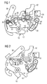
- Fig. 1 is a schematic locking device 10 for a tailgate Motor vehicle shown.
- the locking device 10 has a Rotary trap 12, which is rotatably mounted about a pivot axis 14 and a receptacle 16 has a pin or striker (not shown) for Closing the door can accommodate.
- the closed position is the Shown locking device 10, in which the rotary latch 12 with the aid of a Pawl 18 is locked.
- the pawl 18 is about a second pivot axis 20 pivotally mounted, and has a locking lug 22, depending on the rotational position the catch 12 with a main catch 24 on the catch (see FIG. 1 and 6) or a pre-catch 26 (see FIGS. 3 and 4) cooperates.
- a microswitch 28 detects the closed position of the locking device 10 and is at the illustrated embodiment triggered by the pawl 18.
- the locking device 10 also has a motor-driven closing aid, which acts on a driver lever 30 which is around the first pivot axis 14 of the catch 12 is pivotally mounted.
- a driver lever 30 On the driver lever 30 is a bow-shaped decoupling lever 32 rotatable about a pivot axis 34 stored, one designed in the example shown as a torsion spring Preload spring is provided, which strives to sense the decoupling lever to pivot the display counterclockwise.
- the pivoting ability of the decoupling lever 32 is determined by a driver pin 38 limited, which is arranged on the catch 12 and for example in the closed position shown in FIG. 1 on a contact surface 40 abuts the bow-shaped decoupling lever 32.
- the decoupling lever is located 32 in this driving position, can be done by pivoting the driving lever 30 the catch 12 are taken, which later will be discussed in more detail.
- the locking device 10 has a decoupling and opening mechanism, the actuating lever that can be triggered manually and / or by motor 42 which, like the pawl 18, about the second pivot axis 20 is rotatably mounted.
- the pawl 18 is carried along by the actuating lever 42 takes place via a driver cam 44, which in a recess in the pawl 18 engages a certain relative rotation of the operating lever 42 against the pawl 18 against the load of a second Preload spring 48 allows the torsion spring around the second pivot axis 20 is arranged.
- On the operating lever 42 there is also an unlocking lever 50 integrally formed with an unlocking pin 52 on the decoupling lever 32 interacts, provided the actuating lever 42 in a corresponding Rotational position is brought.
- the decoupling lever 32 radially inward against the load of the first To pivot biasing spring 36 and thereby the driver pin 38th and thus to release the catch 12.
- a sliding element 54 which adapts to the Driver pin 38 connects, acts with a sliding surface 56 on the decoupling lever 32 together and prevents the decoupling element from snapping back 32 with large relative rotation of the driver lever 30 compared the catch 12 with the decoupling lever 32 disengaged.
- an additional lever 58 is provided, by means of which the pawl 18 can be locked in the disengaged position to prevent that after a Opening and decoupling process when the rotary latch 12 is blocked, for example due to a snow load resting on the tailgate of the vehicle, prevents the pawl from snapping back and thus opening the Tailgate allowed.
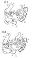
- the locking device 10 is now shown in its open position.
- the catch 12 is clockwise by a corresponding angular amount twisted in the sense of the illustration and thereby gives the body side assembled pin or striker free.
- the pawl 18 is located correspondingly in a position releasing the catch 12, the latching lug 22 under the load of a bias spring (not shown) on an outer surface 60 of the catch 12 is present.
- the actuating lever 42 lies over the driver 44 under the load of the second biasing spring 48 on a first flank 62 of the recess 46 and is almost in one of the positions in FIG. 1 corresponding absolute position.
- the driver lever 30 is also under the load of a biasing spring (not shown) pivoted clockwise as shown, with the Decoupling lever 32 is in its disengaged position and over its Contact surface 56 abuts the driving pin 38 or the sliding element 54.
- a biasing spring (not shown) pivoted clockwise as shown, with the Decoupling lever 32 is in its disengaged position and over its Contact surface 56 abuts the driving pin 38 or the sliding element 54.
- the one penetrating into the receptacle 16 moves Has the rotary latch 12 and rotates it counterclockwise, the latch 22 of the pawl initially snaps into the latch 26 (see FIG. 3) and simultaneously or briefly later the decoupling lever 32 snaps into its driving position, in which it catches the driving pin 38 securely encloses.
- a microswitch (not shown) activated, which triggers the motor drive of the closing aid. This affects the driver lever 30 and thereby ensures the engaged decoupling lever 32 for taking the rotary latch 12 over the one shown in FIG. 5 Intermediate position, in which the locking lug 22 is located between the preliminary catch 26 and the main catch 24 is in the closed starting position as it is has been described in connection with FIG. 1.
- An opening of the locking device 10 is by appropriate pivoting of the operating lever 42 possible.
- the unlocking lever first arrives 50 with the unlocking pin 52 on the decoupling lever 32 in Engagement and transports the latter into its disengaged position.
- the recess 46 ensures that the pawl during this advance of approximately 10 ° 18 remains unchanged and the latch 22 in engagement with the main catch 24 remains.
- the driver 44 takes on a second edge 64 the end of the recess 46 opposite the first flank 62 Pawl 18 and brings the locking lug 22 out of engagement with the main catch 24 (see Fig. 7).
- the biasing spring (not shown) snaps the additional lever 58 with a catch 66 behind a locking projection 68 on the pawl 18 so that it snaps back the pawl 18 is only possible when the additional lever 58 from a disengaging element 70 on the snap catch 12 in its disengaged position is moved.
- a particular advantage of the locking device shown is that an auxiliary opening is also possible if the motorized closing aid already exists has been activated.
- the locking device shown has the advantage in any position and in immediate opening in every operating state by actuating the operating lever 42 to enable. This additional security feature only requires a minimal additional effort on components and does not work with one increased space requirements, so that the locking device easily instead conventional locking device with closing aid can be used.
- the locking device 10 described is not only suitable for use in a tailgate of a vehicle, but also for doors or hoods also outside the automotive sector.
Landscapes
- Lock And Its Accessories (AREA)
Applications Claiming Priority (2)
| Application Number | Priority Date | Filing Date | Title |
|---|---|---|---|
| DE10114438A DE10114438A1 (de) | 2001-03-23 | 2001-03-23 | Schließeinrichtung mit Zuziehhilfe |
| DE10114438 | 2001-03-23 |
Publications (3)
| Publication Number | Publication Date |
|---|---|
| EP1243725A2 true EP1243725A2 (fr) | 2002-09-25 |
| EP1243725A3 EP1243725A3 (fr) | 2003-12-17 |
| EP1243725B1 EP1243725B1 (fr) | 2006-06-07 |
Family
ID=7678823
Family Applications (1)
| Application Number | Title | Priority Date | Filing Date |
|---|---|---|---|
| EP02006062A Expired - Lifetime EP1243725B1 (fr) | 2001-03-23 | 2002-03-18 | Serrure à fermeture assistée |
Country Status (2)
| Country | Link |
|---|---|
| EP (1) | EP1243725B1 (fr) |
| DE (2) | DE10114438A1 (fr) |
Cited By (7)
| Publication number | Priority date | Publication date | Assignee | Title |
|---|---|---|---|---|
| EP1418298A1 (fr) * | 2002-11-05 | 2004-05-12 | Valeo Sicherheitssysteme GmbH | Assitance à la fermeture pour portes de véhicule automobile |
| FR2850698A1 (fr) * | 2003-01-30 | 2004-08-06 | Valeo Securite Habitacle | Serrure pour ouvrant de vehicule automobile, a assistance a la fermeture |
| WO2010142280A1 (fr) * | 2009-06-12 | 2010-12-16 | Kiekert Aktiengesellschaft | Serrure de véhicule automobile avec système d'assistance à la fermeture |
| US20140049056A1 (en) * | 2011-02-28 | 2014-02-20 | Kiekert Aktiengesellschaft | Motor vehicle door lock |
| WO2020211905A1 (fr) * | 2019-04-18 | 2020-10-22 | Kiekert Ag | Serrure de porte, en particulier serrure de porte de véhicule automobile |
| CN112177451A (zh) * | 2020-11-13 | 2021-01-05 | 无锡忻润汽车安全系统有限公司 | 一种一体式电开自吸门锁 |
| CN112523622A (zh) * | 2020-12-18 | 2021-03-19 | 常州市武进华瑞电子有限公司 | 一种具有自锁机构的电池仓锁装置 |
Families Citing this family (4)
| Publication number | Priority date | Publication date | Assignee | Title |
|---|---|---|---|---|
| DE102010049567A1 (de) | 2010-10-26 | 2012-04-26 | Happich Gmbh | Schließeinrichtung, insbesondere für Gebäudetüren |
| DE102018107210A1 (de) * | 2018-03-27 | 2019-10-02 | Kiekert Ag | Kraftfahrzeugtürschloss |
| DE102024103829A1 (de) * | 2024-02-12 | 2025-08-14 | Brose Schließsysteme GmbH & Co. Kommanditgesellschaft | Kraftfahrzeugschloss für ein Kraftfahrzeug |
| DE102024103830A1 (de) * | 2024-02-12 | 2025-08-14 | Brose Schließsysteme GmbH & Co. Kommanditgesellschaft | Kraftfahrzeugschloss für ein Kraftfahrzeug |
Family Cites Families (4)
| Publication number | Priority date | Publication date | Assignee | Title |
|---|---|---|---|---|
| DE4319122C1 (de) * | 1993-06-09 | 1994-10-20 | Daimler Benz Ag | Hilfskraftunterstützter Drehfallenverschluß für Fahrzeuge |
| US5938252A (en) * | 1996-08-22 | 1999-08-17 | Asmo Co., Ltd. | Door member locking/unlocking apparatus |
| US6422615B1 (en) * | 1998-07-20 | 2002-07-23 | Mannesmann Vdo Ag | Closure device with shutting aid |
| DE19904663C2 (de) * | 1999-02-04 | 2001-02-15 | Bosch Gmbh Robert | Kraftfahrzeugtürschloß mit elektrischer Schließhilfe und Öffnungshilfe |
-
2001
- 2001-03-23 DE DE10114438A patent/DE10114438A1/de not_active Ceased
-
2002
- 2002-03-18 EP EP02006062A patent/EP1243725B1/fr not_active Expired - Lifetime
- 2002-03-18 DE DE50207052T patent/DE50207052D1/de not_active Expired - Fee Related
Non-Patent Citations (1)
| Title |
|---|
| None |
Cited By (13)
| Publication number | Priority date | Publication date | Assignee | Title |
|---|---|---|---|---|
| EP1418298A1 (fr) * | 2002-11-05 | 2004-05-12 | Valeo Sicherheitssysteme GmbH | Assitance à la fermeture pour portes de véhicule automobile |
| FR2850698A1 (fr) * | 2003-01-30 | 2004-08-06 | Valeo Securite Habitacle | Serrure pour ouvrant de vehicule automobile, a assistance a la fermeture |
| WO2004074608A1 (fr) * | 2003-01-30 | 2004-09-02 | Valeo Securite Habitacle | Serrure pour ouvrant de vehicule automobile, a assistance a la fermeture |
| US8955889B2 (en) | 2009-06-12 | 2015-02-17 | Kiekert Ag | Motor vehicle lock with a self-locking mechanism |
| WO2010142280A1 (fr) * | 2009-06-12 | 2010-12-16 | Kiekert Aktiengesellschaft | Serrure de véhicule automobile avec système d'assistance à la fermeture |
| US9810004B2 (en) * | 2011-02-28 | 2017-11-07 | Kiekert Aktiengesellschaft | Motor vehicle door lock |
| US20140049056A1 (en) * | 2011-02-28 | 2014-02-20 | Kiekert Aktiengesellschaft | Motor vehicle door lock |
| WO2020211905A1 (fr) * | 2019-04-18 | 2020-10-22 | Kiekert Ag | Serrure de porte, en particulier serrure de porte de véhicule automobile |
| DE102019110253A1 (de) * | 2019-04-18 | 2020-10-22 | Kiekert Aktiengesellschaft | Türschloss insbesondere Kraftfahrzeugtürschloss |
| US12012785B2 (en) | 2019-04-18 | 2024-06-18 | Kiekert Ag | Door lock, in particular motor vehicle door lock |
| CN112177451A (zh) * | 2020-11-13 | 2021-01-05 | 无锡忻润汽车安全系统有限公司 | 一种一体式电开自吸门锁 |
| CN112177451B (zh) * | 2020-11-13 | 2024-05-28 | 无锡忻润汽车安全系统有限公司 | 一种一体式电开自吸门锁 |
| CN112523622A (zh) * | 2020-12-18 | 2021-03-19 | 常州市武进华瑞电子有限公司 | 一种具有自锁机构的电池仓锁装置 |
Also Published As
| Publication number | Publication date |
|---|---|
| DE10114438A1 (de) | 2002-10-02 |
| EP1243725A3 (fr) | 2003-12-17 |
| DE50207052D1 (de) | 2006-07-20 |
| EP1243725B1 (fr) | 2006-06-07 |
Similar Documents
| Publication | Publication Date | Title |
|---|---|---|
| EP3036390B1 (fr) | Fermeture pour portière de véhicule automobile | |
| EP0979915A2 (fr) | Serrure à fermeture assistée | |
| EP3087237B1 (fr) | Dispositif de fermeture pour capot de véhicule et procédé | |
| EP1617023B1 (fr) | Serrure pour ouvrants ou portes d'un véhicule | |
| DE19948052A1 (de) | Öffnungshilfe für Türschlösser | |
| DE102018120697A1 (de) | Federunterstütztes Stellglied für Kraft-Löse- und/oder Anzugsfunktionalität | |
| EP1052356B1 (fr) | Dispositif de fermeture pour porte de véhicule | |
| WO2019076403A1 (fr) | Serrure de porte de véhicule à moteur | |
| DE19933371A1 (de) | Schließeinrichtung mit Zuziehhilfe | |
| DE102008035183B4 (de) | Elektrische Schlösser zum Schließen und Verriegeln von Flügeln, insbesondere Schlösser für Türen von Kraftfahrzeugen | |
| DE10157597A1 (de) | Kraftfahrzeug-Türverschluss | |
| WO2023104236A1 (fr) | Serrure de véhicule automobile combinée | |
| EP1243725B1 (fr) | Serrure à fermeture assistée | |
| DE19616655A1 (de) | Vorrichtung zum Öffnen und Schließen einer Tür oder Klappe | |
| DE102013008415A1 (de) | Kraftfahrzeugschloss | |
| EP2010739A2 (fr) | Fermeture de portière de véhicule à moteur | |
| DE102008024341B4 (de) | Türbetätigungsvorrichtung mit einer Notöffnungseinrichtung | |
| EP1085148B1 (fr) | Serrure à ouverture assistée | |
| DE10114065A1 (de) | Türschloß | |
| EP3688257A1 (fr) | Serrure de véhicule automobile | |
| DE10312093A1 (de) | Drehfallenschloss | |
| EP1493892B1 (fr) | Dispositiv de verrouillage pour une fenêtre ou un volet | |
| DE102008057318A1 (de) | Kraftfahrzeugschloss mit Rückstellung in die Entriegelung | |
| DE4339654A1 (de) | Kraftfahrzeugtürverschluß | |
| EP3385482B1 (fr) | Dispositif de verrouillage pour un véhicule |
Legal Events
| Date | Code | Title | Description |
|---|---|---|---|
| PUAI | Public reference made under article 153(3) epc to a published international application that has entered the european phase |
Free format text: ORIGINAL CODE: 0009012 |
|
| AK | Designated contracting states |
Kind code of ref document: A2 Designated state(s): AT BE CH CY DE DK ES FI FR GB GR IE IT LI LU MC NL PT SE TR |
|
| AX | Request for extension of the european patent |
Free format text: AL;LT;LV;MK;RO;SI |
|
| PUAL | Search report despatched |
Free format text: ORIGINAL CODE: 0009013 |
|
| AK | Designated contracting states |
Kind code of ref document: A3 Designated state(s): AT BE CH CY DE DK ES FI FR GB GR IE IT LI LU MC NL PT SE TR |
|
| AX | Request for extension of the european patent |
Extension state: AL LT LV MK RO SI |
|
| RIC1 | Information provided on ipc code assigned before grant |
Ipc: 7E 05B 65/12 B Ipc: 7E 05B 47/00 B Ipc: 7E 05B 65/32 A |
|
| 17P | Request for examination filed |
Effective date: 20040119 |
|
| AKX | Designation fees paid |
Designated state(s): DE FR |
|
| 17Q | First examination report despatched |
Effective date: 20050603 |
|
| GRAP | Despatch of communication of intention to grant a patent |
Free format text: ORIGINAL CODE: EPIDOSNIGR1 |
|
| GRAS | Grant fee paid |
Free format text: ORIGINAL CODE: EPIDOSNIGR3 |
|
| GRAA | (expected) grant |
Free format text: ORIGINAL CODE: 0009210 |
|
| AK | Designated contracting states |
Kind code of ref document: B1 Designated state(s): DE FR |
|
| REF | Corresponds to: |
Ref document number: 50207052 Country of ref document: DE Date of ref document: 20060720 Kind code of ref document: P |
|
| ET | Fr: translation filed | ||
| PLBE | No opposition filed within time limit |
Free format text: ORIGINAL CODE: 0009261 |
|
| STAA | Information on the status of an ep patent application or granted ep patent |
Free format text: STATUS: NO OPPOSITION FILED WITHIN TIME LIMIT |
|
| 26N | No opposition filed |
Effective date: 20070308 |
|
| PGFP | Annual fee paid to national office [announced via postgrant information from national office to epo] |
Ref country code: DE Payment date: 20070521 Year of fee payment: 6 |
|
| PG25 | Lapsed in a contracting state [announced via postgrant information from national office to epo] |
Ref country code: DE Free format text: LAPSE BECAUSE OF NON-PAYMENT OF DUE FEES Effective date: 20081001 |
|
| PGFP | Annual fee paid to national office [announced via postgrant information from national office to epo] |
Ref country code: FR Payment date: 20080929 Year of fee payment: 7 |
|
| REG | Reference to a national code |
Ref country code: FR Ref legal event code: ST Effective date: 20120309 |
|
| PG25 | Lapsed in a contracting state [announced via postgrant information from national office to epo] |
Ref country code: FR Free format text: LAPSE BECAUSE OF NON-PAYMENT OF DUE FEES Effective date: 20080331 |