EP1243797A2 - Virole pour compresseur de turbine à gaz - Google Patents
Virole pour compresseur de turbine à gaz Download PDFInfo
- Publication number
- EP1243797A2 EP1243797A2 EP02251513A EP02251513A EP1243797A2 EP 1243797 A2 EP1243797 A2 EP 1243797A2 EP 02251513 A EP02251513 A EP 02251513A EP 02251513 A EP02251513 A EP 02251513A EP 1243797 A2 EP1243797 A2 EP 1243797A2
- Authority
- EP
- European Patent Office
- Prior art keywords
- engine
- compressor
- grooves
- radially
- gas turbine
- Prior art date
- Legal status (The legal status is an assumption and is not a legal conclusion. Google has not performed a legal analysis and makes no representation as to the accuracy of the status listed.)
- Withdrawn
Links
Images

Classifications
-
- F—MECHANICAL ENGINEERING; LIGHTING; HEATING; WEAPONS; BLASTING
- F01—MACHINES OR ENGINES IN GENERAL; ENGINE PLANTS IN GENERAL; STEAM ENGINES
- F01D—NON-POSITIVE DISPLACEMENT MACHINES OR ENGINES, e.g. STEAM TURBINES
- F01D11/00—Preventing or minimising internal leakage of working-fluid, e.g. between stages
- F01D11/08—Preventing or minimising internal leakage of working-fluid, e.g. between stages for sealing space between rotor blade tips and stator
-
- F—MECHANICAL ENGINEERING; LIGHTING; HEATING; WEAPONS; BLASTING
- F04—POSITIVE - DISPLACEMENT MACHINES FOR LIQUIDS; PUMPS FOR LIQUIDS OR ELASTIC FLUIDS
- F04D—NON-POSITIVE-DISPLACEMENT PUMPS
- F04D29/00—Details, component parts, or accessories
- F04D29/08—Sealings
- F04D29/16—Sealings between pressure and suction sides
- F04D29/161—Sealings between pressure and suction sides especially adapted for elastic fluid pumps
- F04D29/164—Sealings between pressure and suction sides especially adapted for elastic fluid pumps of an axial flow wheel
-
- F—MECHANICAL ENGINEERING; LIGHTING; HEATING; WEAPONS; BLASTING
- F04—POSITIVE - DISPLACEMENT MACHINES FOR LIQUIDS; PUMPS FOR LIQUIDS OR ELASTIC FLUIDS
- F04D—NON-POSITIVE-DISPLACEMENT PUMPS
- F04D29/00—Details, component parts, or accessories
- F04D29/40—Casings; Connections of working fluid
- F04D29/52—Casings; Connections of working fluid for axial pumps
- F04D29/522—Casings; Connections of working fluid for axial pumps especially adapted for elastic fluid pumps
- F04D29/526—Details of the casing section radially opposing blade tips
-
- F—MECHANICAL ENGINEERING; LIGHTING; HEATING; WEAPONS; BLASTING
- F04—POSITIVE - DISPLACEMENT MACHINES FOR LIQUIDS; PUMPS FOR LIQUIDS OR ELASTIC FLUIDS
- F04D—NON-POSITIVE-DISPLACEMENT PUMPS
- F04D29/00—Details, component parts, or accessories
- F04D29/66—Combating cavitation, whirls, noise, vibration or the like; Balancing
- F04D29/68—Combating cavitation, whirls, noise, vibration or the like; Balancing by influencing boundary layers
- F04D29/681—Combating cavitation, whirls, noise, vibration or the like; Balancing by influencing boundary layers especially adapted for elastic fluid pumps
- F04D29/685—Inducing localised fluid recirculation in the stator-rotor interface
-
- Y—GENERAL TAGGING OF NEW TECHNOLOGICAL DEVELOPMENTS; GENERAL TAGGING OF CROSS-SECTIONAL TECHNOLOGIES SPANNING OVER SEVERAL SECTIONS OF THE IPC; TECHNICAL SUBJECTS COVERED BY FORMER USPC CROSS-REFERENCE ART COLLECTIONS [XRACs] AND DIGESTS
- Y10—TECHNICAL SUBJECTS COVERED BY FORMER USPC
- Y10S—TECHNICAL SUBJECTS COVERED BY FORMER USPC CROSS-REFERENCE ART COLLECTIONS [XRACs] AND DIGESTS
- Y10S415/00—Rotary kinetic fluid motors or pumps
- Y10S415/914—Device to control boundary layer
Definitions
- This invention relates generally to gas turbine engines and more particularly to an improved compressor casing for a gas turbine engine that minimizes the deleterious effect of foreign object ingestion into the engine without compromising surge margin of the engine, thereby to enhance its utility as the power plant of an aircraft.
- a typical gas turbine engine comprises a compressor, a combustor and a turbine in fluid flow relation.
- a variant of the typical engine includes a fan disposed forwardly of the compressor and an annular by-pass duct that surrounds the compressor.
- the present invention solves the aforesaid problem by utilizing a plurality of radially inwardly and axially rearwardly opening circumferential grooves in the compressor casing.
- the grooves are disposed slightly downstream of a line swept by the leading edge of the fan or compressor blade tip.
- the inclined grooves offer reduced target and entrapment area for debris.
- Axially spaced, circumferential fins defining the grooves are sufficiently deformable so as to close upon initial impact by debris, thus minimizing the opportunity for debris entrapment.
- the casing grooves are preferably used in conjunction with backswept fan or compressor blades and provide fan or compressor surge margin in the conventional manner.
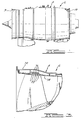
- a typical environment in which the present invention has utility comprises a by-pass turbofan engine 6 having a cylindrical casing 8 defining an air intake 9 at the front thereof and an annular by-pass duct 10 extending to the rear thereof.
- a low pressure spool assembly 12 is rotatable about a central longitudinal axis 14 of the engine 6 and comprises a shaft 16 having a fan 18 and an intermediate pressure compressor stage 20 at the forward end thereof.
- An intermediate pressure turbine 22 and a low-pressure turbine 24 are disposed on the aft end of the shaft 16.
- a high pressure spool assembly 26 is telescoped over the low pressure spool 12 in coaxial relation thereto and comprises a shaft 32 having a high pressure compressor 34 at a forward end thereof and a high pressure turbine 36 at the aft end thereof.
- An annular combustor 40 is disposed about the low and high-pressure spools 12 and 26, respectively, between the high-pressure compressor 34 and high-pressure turbine 36.
- the flow of air induced by the fan 18 of the engine 6 is split, combustion air flowing to the low-pressure compressor 20 and by-pass air flowing to the by-pass duct 10.
- Combustion air flows from the low-pressure compressor 20 to the high-pressure compressor 34, thence to the combustor 40 wherein fuel is introduced and burned.
- Combustion gases pass through the high-pressure turbine 36, thence through the intermediate and low pressure turbines 22 and 24, respectively.
- a forward end 70 of the engine casing 8 is provided with a plurality of radially inwardly and axially rearwardly opening annular grooves 72 on a radially inner surface 74 thereof.
- the grooves 72 are defined by fins 76 which extend radially inwardly and axially rearwardly from the casing 8. Because the grooves 72 open rearwardly of the casing 8, the axially rearward inertia component of a foreign object ingested into the engine 6 is utilized to clear the grooves 72. Moreover, impact of a relatively heavy object against the radially inner edges of the fins 76 tends to bend the fins 76 radially outwardly and rearwardly so as to close the grooves 72 therebetween.
Landscapes
- Engineering & Computer Science (AREA)
- Mechanical Engineering (AREA)
- General Engineering & Computer Science (AREA)
- Structures Of Non-Positive Displacement Pumps (AREA)
Applications Claiming Priority (2)
| Application Number | Priority Date | Filing Date | Title |
|---|---|---|---|
| US812001 | 2001-03-19 | ||
| US09/812,001 US6499940B2 (en) | 2001-03-19 | 2001-03-19 | Compressor casing for a gas turbine engine |
Publications (2)
| Publication Number | Publication Date |
|---|---|
| EP1243797A2 true EP1243797A2 (fr) | 2002-09-25 |
| EP1243797A3 EP1243797A3 (fr) | 2004-09-08 |
Family
ID=25208188
Family Applications (1)
| Application Number | Title | Priority Date | Filing Date |
|---|---|---|---|
| EP02251513A Withdrawn EP1243797A3 (fr) | 2001-03-19 | 2002-03-05 | Virole pour compresseur de turbine à gaz |
Country Status (3)
| Country | Link |
|---|---|
| US (1) | US6499940B2 (fr) |
| EP (1) | EP1243797A3 (fr) |
| CA (1) | CA2372325A1 (fr) |
Cited By (4)
| Publication number | Priority date | Publication date | Assignee | Title |
|---|---|---|---|---|
| EP1801361A1 (fr) * | 2005-12-22 | 2007-06-27 | Rolls-Royce plc | Boîtier de ventilateur ou de compresseur |
| WO2008056454A1 (fr) * | 2006-11-08 | 2008-05-15 | Ihi Corporation | Aube de stator et aube de rotor de compresseur |
| US8506234B2 (en) | 2009-05-05 | 2013-08-13 | Rolls-Royce Plc | Duct wall for a fan of a gas turbine engine |
| EP2990601A1 (fr) * | 2014-08-28 | 2016-03-02 | Honeywell International Inc. | Procédé pour améliorer la performance d'un moteur à turbine à gaz |
Families Citing this family (18)
| Publication number | Priority date | Publication date | Assignee | Title |
|---|---|---|---|---|
| GB0216952D0 (en) * | 2002-07-20 | 2002-08-28 | Rolls Royce Plc | Gas turbine engine casing and rotor blade arrangement |
| US7029232B2 (en) * | 2003-02-27 | 2006-04-18 | Rolls-Royce Plc | Abradable seals |
| GB0600532D0 (en) * | 2006-01-12 | 2006-02-22 | Rolls Royce Plc | A blade and rotor arrangement |
| US20090065064A1 (en) * | 2007-08-02 | 2009-03-12 | The University Of Notre Dame Du Lac | Compressor tip gap flow control using plasma actuators |
| US7988410B1 (en) | 2007-11-19 | 2011-08-02 | Florida Turbine Technologies, Inc. | Blade tip shroud with circular grooves |
| GB0807358D0 (en) * | 2008-04-23 | 2008-05-28 | Rolls Royce Plc | Fan blade |
| US8337146B2 (en) * | 2009-06-03 | 2012-12-25 | Pratt & Whitney Canada Corp. | Rotor casing treatment with recessed baffles |
| FR2961564B1 (fr) * | 2010-06-17 | 2016-03-04 | Snecma | Compresseur et turbomachine a rendement optimise |
| GB2483060B (en) | 2010-08-23 | 2013-05-15 | Rolls Royce Plc | A turbomachine casing assembly |
| WO2014163673A2 (fr) | 2013-03-11 | 2014-10-09 | Bronwyn Power | Géométrie de voie d'écoulement de turbine à gaz |
| EP2971547B1 (fr) * | 2013-03-12 | 2020-01-01 | United Technologies Corporation | Stator en porte-à-faux comportant une caractéristique de déclenchement de tourbillon |
| US10465716B2 (en) | 2014-08-08 | 2019-11-05 | Pratt & Whitney Canada Corp. | Compressor casing |
| US10066640B2 (en) * | 2015-02-10 | 2018-09-04 | United Technologies Corporation | Optimized circumferential groove casing treatment for axial compressors |
| US10107307B2 (en) | 2015-04-14 | 2018-10-23 | Pratt & Whitney Canada Corp. | Gas turbine engine rotor casing treatment |
| US10487847B2 (en) | 2016-01-19 | 2019-11-26 | Pratt & Whitney Canada Corp. | Gas turbine engine blade casing |
| US10465539B2 (en) * | 2017-08-04 | 2019-11-05 | Pratt & Whitney Canada Corp. | Rotor casing |
| US11346367B2 (en) | 2019-07-30 | 2022-05-31 | Pratt & Whitney Canada Corp. | Compressor rotor casing with swept grooves |
| US11199106B1 (en) * | 2020-08-21 | 2021-12-14 | Hamilton Sundstrand Corporation | Blade containment device |
Family Cites Families (6)
| Publication number | Priority date | Publication date | Assignee | Title |
|---|---|---|---|---|
| GB2017228B (en) * | 1977-07-14 | 1982-05-06 | Pratt & Witney Aircraft Of Can | Shroud for a turbine rotor |
| FR2558900B1 (fr) * | 1984-02-01 | 1988-05-27 | Snecma | Dispositif d'etancheite peripherique d'aubage de compresseur axial |
| US4738586A (en) * | 1985-03-11 | 1988-04-19 | United Technologies Corporation | Compressor blade tip seal |
| JP3816150B2 (ja) * | 1995-07-18 | 2006-08-30 | 株式会社荏原製作所 | 遠心流体機械 |
| US6231301B1 (en) * | 1998-12-10 | 2001-05-15 | United Technologies Corporation | Casing treatment for a fluid compressor |
| US6350102B1 (en) * | 2000-07-19 | 2002-02-26 | General Electric Company | Shroud leakage flow discouragers |
-
2001
- 2001-03-19 US US09/812,001 patent/US6499940B2/en not_active Expired - Lifetime
-
2002
- 2002-02-19 CA CA002372325A patent/CA2372325A1/fr not_active Abandoned
- 2002-03-05 EP EP02251513A patent/EP1243797A3/fr not_active Withdrawn
Cited By (6)
| Publication number | Priority date | Publication date | Assignee | Title |
|---|---|---|---|---|
| EP1801361A1 (fr) * | 2005-12-22 | 2007-06-27 | Rolls-Royce plc | Boîtier de ventilateur ou de compresseur |
| WO2008056454A1 (fr) * | 2006-11-08 | 2008-05-15 | Ihi Corporation | Aube de stator et aube de rotor de compresseur |
| US8459939B2 (en) | 2006-11-08 | 2013-06-11 | Ihi Corporation | Compressor stator blade and compressor rotor blade |
| US8506234B2 (en) | 2009-05-05 | 2013-08-13 | Rolls-Royce Plc | Duct wall for a fan of a gas turbine engine |
| EP2990601A1 (fr) * | 2014-08-28 | 2016-03-02 | Honeywell International Inc. | Procédé pour améliorer la performance d'un moteur à turbine à gaz |
| US10046424B2 (en) | 2014-08-28 | 2018-08-14 | Honeywell International Inc. | Rotors with stall margin and efficiency optimization and methods for improving gas turbine engine performance therewith |
Also Published As
| Publication number | Publication date |
|---|---|
| CA2372325A1 (fr) | 2002-09-19 |
| US20020131858A1 (en) | 2002-09-19 |
| US6499940B2 (en) | 2002-12-31 |
| EP1243797A3 (fr) | 2004-09-08 |
Similar Documents
| Publication | Publication Date | Title |
|---|---|---|
| US6499940B2 (en) | Compressor casing for a gas turbine engine | |
| US8186962B2 (en) | Fan rotating blade for turbofan engine | |
| US6227794B1 (en) | Fan case with flexible conical ring | |
| US5182906A (en) | Hybrid spinner nose configuration in a gas turbine engine having a bypass duct | |
| US7891163B2 (en) | Engine | |
| JP5009581B2 (ja) | 可変ファン出口案内静翼を備えるターボファンガスタービンエンジン | |
| JP2005113919A5 (fr) | ||
| US8955304B2 (en) | Gas turbine engine with modular cores and propulsion unit | |
| US6935840B2 (en) | Low cycle fatigue life (LCF) impeller design concept | |
| US7500364B2 (en) | System for coupling flow from a centrifugal compressor to an axial combustor for gas turbines | |
| US5277541A (en) | Vaned shroud for centrifugal compressor | |
| CA2482324A1 (fr) | Turbine a gaz a systeme de soufflante a taux de compression variable | |
| US10683806B2 (en) | Protected core inlet with reduced capture area | |
| US6962479B2 (en) | Compound centrifugal and screw compressor | |
| CA2944453C (fr) | Pot d'helice d'aeronef a rendement ameliore par vent de travers | |
| US11098646B2 (en) | Gas turbine impeller nose cone | |
| US9970452B2 (en) | Forward-swept impellers and gas turbine engines employing the same | |
| CA2964988C (fr) | Systeme et methode d'influence du flux dans un ventilateur d'une turbine a gaz | |
| EP1809893B1 (fr) | Stator pour moteur a reaction, moteur a reaction pourvu de ce stator, et aeronef equipe de ce moteur a reaction | |
| JP4143901B2 (ja) | ターボファンエンジン | |
| EP3473841A1 (fr) | Moteur à double flux | |
| US20200096002A1 (en) | Axial compressor | |
| GB1597376A (en) | Nose bullet for a gas turbine engine |
Legal Events
| Date | Code | Title | Description |
|---|---|---|---|
| PUAI | Public reference made under article 153(3) epc to a published international application that has entered the european phase |
Free format text: ORIGINAL CODE: 0009012 |
|
| AK | Designated contracting states |
Kind code of ref document: A2 Designated state(s): AT BE CH CY DE DK ES FI FR GB GR IE IT LI LU MC NL PT SE TR |
|
| AX | Request for extension of the european patent |
Free format text: AL;LT;LV;MK;RO;SI |
|
| PUAL | Search report despatched |
Free format text: ORIGINAL CODE: 0009013 |
|
| AK | Designated contracting states |
Kind code of ref document: A3 Designated state(s): AT BE CH CY DE DK ES FI FR GB GR IE IT LI LU MC NL PT SE TR |
|
| AX | Request for extension of the european patent |
Extension state: AL LT LV MK RO SI |
|
| AKX | Designation fees paid | ||
| REG | Reference to a national code |
Ref country code: DE Ref legal event code: 8566 |
|
| STAA | Information on the status of an ep patent application or granted ep patent |
Free format text: STATUS: THE APPLICATION IS DEEMED TO BE WITHDRAWN |
|
| 18D | Application deemed to be withdrawn |
Effective date: 20050309 |