EP1243855A2 - Arrangement de joints d'étanchéité pour la connexion de deux tuyaux - Google Patents
Arrangement de joints d'étanchéité pour la connexion de deux tuyaux Download PDFInfo
- Publication number
- EP1243855A2 EP1243855A2 EP02005680A EP02005680A EP1243855A2 EP 1243855 A2 EP1243855 A2 EP 1243855A2 EP 02005680 A EP02005680 A EP 02005680A EP 02005680 A EP02005680 A EP 02005680A EP 1243855 A2 EP1243855 A2 EP 1243855A2
- Authority
- EP
- European Patent Office
- Prior art keywords
- sealing
- ring
- sealing arrangement
- arrangement according
- pipes
- Prior art date
- Legal status (The legal status is an assumption and is not a legal conclusion. Google has not performed a legal analysis and makes no representation as to the accuracy of the status listed.)
- Granted
Links
Images

Classifications
-
- F—MECHANICAL ENGINEERING; LIGHTING; HEATING; WEAPONS; BLASTING
- F01—MACHINES OR ENGINES IN GENERAL; ENGINE PLANTS IN GENERAL; STEAM ENGINES
- F01N—GAS-FLOW SILENCERS OR EXHAUST APPARATUS FOR MACHINES OR ENGINES IN GENERAL; GAS-FLOW SILENCERS OR EXHAUST APPARATUS FOR INTERNAL-COMBUSTION ENGINES
- F01N13/00—Exhaust or silencing apparatus characterised by constructional features
- F01N13/18—Construction facilitating manufacture, assembly, or disassembly
- F01N13/1838—Construction facilitating manufacture, assembly, or disassembly characterised by the type of connection between parts of exhaust or silencing apparatus, e.g. between housing and tubes, between tubes and baffles
- F01N13/1844—Mechanical joints
-
- F—MECHANICAL ENGINEERING; LIGHTING; HEATING; WEAPONS; BLASTING
- F01—MACHINES OR ENGINES IN GENERAL; ENGINE PLANTS IN GENERAL; STEAM ENGINES
- F01N—GAS-FLOW SILENCERS OR EXHAUST APPARATUS FOR MACHINES OR ENGINES IN GENERAL; GAS-FLOW SILENCERS OR EXHAUST APPARATUS FOR INTERNAL-COMBUSTION ENGINES
- F01N13/00—Exhaust or silencing apparatus characterised by constructional features
- F01N13/18—Construction facilitating manufacture, assembly, or disassembly
- F01N13/1805—Fixing exhaust manifolds, exhaust pipes or pipe sections to each other, to engine or to vehicle body
- F01N13/1827—Sealings specially adapted for exhaust systems
-
- F—MECHANICAL ENGINEERING; LIGHTING; HEATING; WEAPONS; BLASTING
- F16—ENGINEERING ELEMENTS AND UNITS; GENERAL MEASURES FOR PRODUCING AND MAINTAINING EFFECTIVE FUNCTIONING OF MACHINES OR INSTALLATIONS; THERMAL INSULATION IN GENERAL
- F16L—PIPES; JOINTS OR FITTINGS FOR PIPES; SUPPORTS FOR PIPES, CABLES OR PROTECTIVE TUBING; MEANS FOR THERMAL INSULATION IN GENERAL
- F16L27/00—Adjustable joints; Joints allowing movement
- F16L27/10—Adjustable joints; Joints allowing movement comprising a flexible connection only
- F16L27/1004—Adjustable joints; Joints allowing movement comprising a flexible connection only introduced in exhaust pipes for hot gases
Definitions
- the invention relates to a sealing arrangement for sealing a junction of two pipes, one of which is at the junction engages in the other, the sealing arrangement having a sealing ring and a fixing ring for fixing the sealing ring on the Connection point includes.
- the invention preferably relates to a sealing arrangement for sealing the junction of two Pipes of an exhaust pipe system for exhaust systems.
- Such exhaust pipe systems often have a plurality of thin-walled ones Metal pipes on, being at the junction of two pipes one of the two pipes with its one end in the adjacent end of the other tube is inserted.
- the junction between the Pipe is by means of a sealing arrangement of the type considered here against the escape of flue gases etc. caused by the exhaust pipe system to be dissipated to seal.
- a sealing arrangement of the type mentioned is from DE 200 11 766 U1 known.
- the sealing ring of this known sealing arrangement has a special profile of two over a connecting section interconnected legs to limit one to the inside of the sealing profile ring open circulation groove.
- the circumferential groove takes radially outwards arched and to create a positive connection between the tubes provided beads on.
- a radially outside on the serves as a fixing ring Sealing ring seated tube spring.
- the invention has for its object a sealing arrangement to provide the type mentioned, which with simple means a effective sealing of the connection point enables and reliable works.
- the invention proposes that the Fixing ring is set up, the sealing ring directly at the end edge or to fix it at the axial end of the radially outer tube in such a way that the sealing ring is the connection point at the transition between the seals radially inner tube to the radially outer tube circumferentially.
- the invention enables the use of a sealing ring with a simple, uncomplicated profile, for example round profile, for Sealing the connection point. It can be, for example act simple commercial O-ring.
- a major advantage is moreover it can be seen in the fact that the sealing ring is the connection point directly in the area of the radial transition from the inner tube to seals the outer tube at the end edge of the outer tube. flue gas and / or condensate cannot escape at the connection point. It should also be added that the sealing arrangement according to the invention can ensure a reliable seal even if an easy-to-install sealing ring with a relatively small cross-section is used.
- the sealing arrangement according to the invention is the fixing ring as a clamping band with each other in the circumferential direction overlapping and fixed to each other in the area of overlap Clamp band ends trained.
- the circumferential length of the clamping band should be changeable adjustable and fixable, as for example by Hose clamps or pipe clamps are known ago. By changing the The circumferential length of the clamping band can be that of the clamping band on the sealing ring applied contact pressure can be varied.
- Clamping tapes also in sealing arrangements according to the invention for different pipe diameters can be used.
- the fixing ring preferably designed as a clamping band the sealing ring in the assembly arrangement all around radially outside like a hood enclose so that the sealing ring in front of outer, e.g. mechanical Influences is protected.
- the fixing ring can be used for hood-shaped encirclement and fixing the sealing ring can be formed in a suitable manner, the Dome-like cross section of the fixing ring, for example, radially curved outwards have the shape of an arc or V-shape or U-shape can be designed.
- the two tubes in the area of their overlapping ends radially outward each ensure a positive connection Beading on, in a further preferred embodiment of the Sealing arrangement the clamping band the beads radially outside hood-like enclose.
- One advantage of this development of the invention is stabilization the connection of the two pipe ends in the axial direction. About that in addition, by appropriate choice of the tension of the clamping band a fixation of the two pipes against twisting around the perpendicular to their rotating connection axis can be reached. On Another advantage of this training in combination with the bead is in it to see that the sealing arrangement in its intended Sealing position is securely fixed.
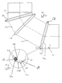
- a pipe bend is shown schematically, as typically in an exhaust pipe system can occur.
- the elbow consists of a plurality of interconnected pipes 1, 2, 3 and 4, which are preferred have a circular cross-section and in the example from one Metal, e.g. Stainless steel or aluminum.
- One of the pipes reaches into the other Tube one.
- Each of the three junctions shown in Fig. 1 is with one sealed respective sealing arrangement according to the invention.
- the adjacent tubes 1 and 2 are each with a bead Mistake.
- the bead 1a of the tube 1 can be seen in Figures 1 and 2, the end of the tube 2 with a not shown bead lies radially within the bead 1a.
- the connection needs the pipes 1 and 2 are not to be made by means of beads, the two Pipe ends of pipes 1 and 2 can e.g. also trained in this way be that the inner radius of a tube is greater than or equal to the outer radius of the other pipe, so the pipe end with the larger one Diameter pushed over the pipe end with the smaller diameter can be.
- the junction between tube 1 and tube 2 is at the end of the radially outer tube 1 directly in the area of step S. the sealing arrangement 5, 8 sealed.
- a commercially available O-ring serves as the sealing ring 8 an elastomeric material, such as rubber.
- the O-ring 8 will all around by a hood enclosing it radially from the outside Clamping band 5 fixed to step S and at the same time against the axial end of the radially outer tube 1 and pressed against the tube 2, so that all around the sealing effect of the O-ring 8 is reinforced.
- the clamping band 5 thus forms a fixing ring for fixing the sealing ring 8 in the sealing position.
- it consists of a metal, e.g. Stainless steel or aluminum.
- a force is exerted in the direction of step S, creating a force component of the O-ring 8 all the way to the axial end of the radially outer Tube 1 is generated and a force component all around the tube 2nd acts, so that the sealing effect of the connection point all around is reinforced.
- the clamping band 5 encloses like a hood the bead 1a radially from the outside, with the O-ring 8 lying away Leg 5a of the clamping band 5 on the shoulder facing away from the O-ring 8 the bead 1a comes to rest.
- the sealing arrangement 5, 8 is fixed in the axial direction. At the same time, this fixes the connection between the two Pipes 1 and 2 against loosening of the two pipes 1 and 2 from each other.
- a suitable tension of the clamping band 5 can by Friction of the sealing arrangement with the two tubes 1 and 2 additionally prevents twisting of the two tubes 1 and 2 relative to each other become.
- the clamping band 5 is in the manner of a hose clamp formed, its ends 5e, 5f in the circumferential direction to each other overlap in one area and the circumferential length of the clamping band 5 by changing the overlap area, for example via a Screw gear 5d is adjustable and fixable.
- the clamping band 5 in which a circumferential length is set, in which the clamping band 5 easily over the connection points of the pipes streaked, placed over the junction of the two pipes 1 and 2 becomes.
- the circumference of the clamping band 5 is reduced so far that the O-ring 8 and the bead 1a are enclosed like a hood, so that the O-ring 8 immediately at the axial end of the radially outer Pipe is fixed so that it is the connection point at the transition between seals the radially inner tube 2 to the radially outer tube 1 all around.
- the scope of the clamping band 5 is preferably set in this way and fixes that the clamping band 5 exerts pressure on the O-ring 8 exercises such that the sealing effect of the O-ring 8 is reinforced and that the connection between tube 1 and tube 2 in particular is fixed in such a way that twisting of the two tubes 1 and 2 against each other is prevented.
- the sealing arrangement 5, 8 a simple and effective measure for sealing and Fixing the connection point.
- the elements 5, 8 can be compared be compact and filigree, so that the sealing arrangement looks inconspicuous or pleasing from the optical design.
- sealing ring 8 with an O-ring Round cross-section was used in alternative embodiments Sealing rings with suitable other cross sections are used become.
Landscapes
- Engineering & Computer Science (AREA)
- General Engineering & Computer Science (AREA)
- Mechanical Engineering (AREA)
- Chemical & Material Sciences (AREA)
- Combustion & Propulsion (AREA)
- Joints With Sleeves (AREA)
- Gasket Seals (AREA)
Applications Claiming Priority (2)
| Application Number | Priority Date | Filing Date | Title |
|---|---|---|---|
| DE20105012U | 2001-03-22 | ||
| DE20105012U DE20105012U1 (de) | 2001-03-22 | 2001-03-22 | Dichtungsanordnung zur Abdichtung einer Verbindungsstelle von zwei miteinander verbundenen Rohren |
Publications (3)
| Publication Number | Publication Date |
|---|---|
| EP1243855A2 true EP1243855A2 (fr) | 2002-09-25 |
| EP1243855A3 EP1243855A3 (fr) | 2003-10-08 |
| EP1243855B1 EP1243855B1 (fr) | 2007-09-26 |
Family
ID=7954698
Family Applications (1)
| Application Number | Title | Priority Date | Filing Date |
|---|---|---|---|
| EP02005680A Expired - Lifetime EP1243855B1 (fr) | 2001-03-22 | 2002-03-12 | Arrangement de joints d'étanchéité pour la connexion de deux tuyaux |
Country Status (3)
| Country | Link |
|---|---|
| EP (1) | EP1243855B1 (fr) |
| AT (1) | ATE374342T1 (fr) |
| DE (2) | DE20105012U1 (fr) |
Family Cites Families (13)
| Publication number | Priority date | Publication date | Assignee | Title |
|---|---|---|---|---|
| DE868542C (de) * | 1941-02-09 | 1953-02-26 | Westdeutsche Mannesmannroehren | Muffenrohrverbindung |
| US2269664A (en) * | 1941-03-14 | 1942-01-13 | United Specialties Co | Seal construction |
| FR1012286A (fr) | 1950-02-09 | 1952-07-08 | Dispositif d'assemblage rapide de tuyaux | |
| DE1728260U (de) | 1956-06-05 | 1956-08-16 | Ferndorf Eisen Metall | Gelenkige rohrverbindung. |
| US3913955A (en) * | 1973-07-05 | 1975-10-21 | Deere & Co | Sealed coupling for exhaust pipe sections |
| DE2807893A1 (de) | 1978-02-24 | 1979-08-30 | Ruhrkohle Ag | Rohrkupplung |
| GB2153026B (en) | 1984-01-20 | 1987-05-13 | Alcolite Products Corp | Clamping for flanged ducts |
| DE3509774A1 (de) * | 1985-03-19 | 1986-10-02 | Witzenmann GmbH, Metallschlauch-Fabrik Pforzheim, 7530 Pforzheim | Rohrverbindung |
| FR2685025B1 (fr) * | 1991-12-13 | 1998-10-09 | Daniel Urion | Segment a double emboitement pour conduit de fumee. |
| DE4308013A1 (de) | 1993-03-13 | 1994-09-15 | Meinig Metu System | Auf ein dünnwandiges Blechrohr aufsetzbarer Flanschring |
| JPH07248083A (ja) | 1994-03-11 | 1995-09-26 | Sango Co Ltd | 管の継手装置 |
| DE19542793C2 (de) | 1995-11-16 | 2000-09-14 | Konrad Schauer | Verbindungsvorrichtung zur flüssigkeitsdichten Verbindung von Rohrleitungen |
| ATE313752T1 (de) * | 2001-01-08 | 2006-01-15 | Neoterm Internat Trading Inc | Dichtungsring für modulare leitungen und modulare leitung mit einem derartigen dichtungsring |
-
2001
- 2001-03-22 DE DE20105012U patent/DE20105012U1/de not_active Expired - Lifetime
-
2002
- 2002-03-12 DE DE50210949T patent/DE50210949D1/de not_active Expired - Lifetime
- 2002-03-12 EP EP02005680A patent/EP1243855B1/fr not_active Expired - Lifetime
- 2002-03-12 AT AT02005680T patent/ATE374342T1/de not_active IP Right Cessation
Also Published As
| Publication number | Publication date |
|---|---|
| DE20105012U1 (de) | 2001-09-13 |
| DE50210949D1 (de) | 2007-11-08 |
| EP1243855A3 (fr) | 2003-10-08 |
| EP1243855B1 (fr) | 2007-09-26 |
| ATE374342T1 (de) | 2007-10-15 |
Similar Documents
| Publication | Publication Date | Title |
|---|---|---|
| DE69825637T2 (de) | Dichtring für röhrenförmiges Element | |
| DE69411935T2 (de) | Schlauchschelle | |
| EP0432436B1 (fr) | Elément de conduite flexible pour tyaux d'échappement de moteurs de véhicules à combustion interne | |
| DE69002721T2 (de) | Rohrverbindung. | |
| DE3926626A1 (de) | Rohrkupplung zum verbinden der enden zweier rohre | |
| DE102017121994A1 (de) | Profilschelle mit Dichtelement | |
| DE9300184U1 (de) | Kabelendkappe | |
| DE2922403A1 (de) | Rohrverbindungsstueck | |
| DE2945668A1 (de) | Klammer | |
| EP0061569A1 (fr) | Manchon | |
| EP1243855B1 (fr) | Arrangement de joints d'étanchéité pour la connexion de deux tuyaux | |
| DE102013015895B4 (de) | Pressfitting und Verbindungsanordnung mit einem solchen Pressfitting | |
| DE202009009217U1 (de) | Spannring für Schläuche | |
| CH689023A5 (de) | Brandmanschette. | |
| DE4103702C1 (fr) | ||
| EP0498322B1 (fr) | Dispositif d'étanchéité pour l'assemblage de deux extrémités à tuyaux cylindriques et lisses | |
| DE102006029242B4 (de) | Flanschverbindung | |
| DE102012005943A1 (de) | Vorrichtung zum Verbinden von zwei Rundkörpern mit unterschiedlichen Außendurchmessern | |
| EP3401584B1 (fr) | Tuyau, en particulier tuyau de gaz d'échappement | |
| DE102009033247B3 (de) | Kupplung mit Ausklinkungen | |
| DE3246136C1 (de) | Rohrkupplung | |
| DE20011766U1 (de) | Dichtprofilring zur Abdichtung einer Verbindungsstelle von zwei miteinander verbundenen Rohren eines Abgasleitungssystems für Abgasanlagen | |
| CH615261A5 (en) | Corrugated tube compensator | |
| EP0122329A1 (fr) | Collier de serrage annulaire | |
| CH683554A5 (de) | Rohrleitungskupplung, Rohrleitung sowie Verfahren zur Montage einer Rohrleitung. |
Legal Events
| Date | Code | Title | Description |
|---|---|---|---|
| PUAI | Public reference made under article 153(3) epc to a published international application that has entered the european phase |
Free format text: ORIGINAL CODE: 0009012 |
|
| AK | Designated contracting states |
Kind code of ref document: A2 Designated state(s): AT BE CH CY DE DK ES FI FR GB GR IE IT LI LU MC NL PT SE TR |
|
| AX | Request for extension of the european patent |
Free format text: AL;LT;LV;MK;RO;SI |
|
| PUAL | Search report despatched |
Free format text: ORIGINAL CODE: 0009013 |
|
| AK | Designated contracting states |
Kind code of ref document: A3 Designated state(s): AT BE CH CY DE DK ES FI FR GB GR IE IT LI LU MC NL PT SE TR |
|
| AX | Request for extension of the european patent |
Extension state: AL LT LV MK RO SI |
|
| 17P | Request for examination filed |
Effective date: 20040310 |
|
| AKX | Designation fees paid |
Designated state(s): AT BE CH CY DE DK ES FI FR GB GR IE IT LI LU MC NL PT SE TR |
|
| RAP1 | Party data changed (applicant data changed or rights of an application transferred) |
Owner name: KUTZNER + WEBER GMBH |
|
| 17Q | First examination report despatched |
Effective date: 20060308 |
|
| GRAP | Despatch of communication of intention to grant a patent |
Free format text: ORIGINAL CODE: EPIDOSNIGR1 |
|
| GRAS | Grant fee paid |
Free format text: ORIGINAL CODE: EPIDOSNIGR3 |
|
| GRAA | (expected) grant |
Free format text: ORIGINAL CODE: 0009210 |
|
| AK | Designated contracting states |
Kind code of ref document: B1 Designated state(s): AT BE CH CY DE DK ES FI FR GB GR IE IT LI LU MC NL PT SE TR |
|
| REG | Reference to a national code |
Ref country code: GB Ref legal event code: FG4D Free format text: NOT ENGLISH |
|
| REG | Reference to a national code |
Ref country code: CH Ref legal event code: EP |
|
| REG | Reference to a national code |
Ref country code: CH Ref legal event code: NV Representative=s name: A. BRAUN, BRAUN, HERITIER, ESCHMANN AG PATENTANWAE |
|
| REF | Corresponds to: |
Ref document number: 50210949 Country of ref document: DE Date of ref document: 20071108 Kind code of ref document: P |
|
| REG | Reference to a national code |
Ref country code: IE Ref legal event code: FG4D Free format text: LANGUAGE OF EP DOCUMENT: GERMAN |
|
| GBT | Gb: translation of ep patent filed (gb section 77(6)(a)/1977) |
Effective date: 20071204 |
|
| PG25 | Lapsed in a contracting state [announced via postgrant information from national office to epo] |
Ref country code: FI Free format text: LAPSE BECAUSE OF FAILURE TO SUBMIT A TRANSLATION OF THE DESCRIPTION OR TO PAY THE FEE WITHIN THE PRESCRIBED TIME-LIMIT Effective date: 20070926 |
|
| ET | Fr: translation filed | ||
| PG25 | Lapsed in a contracting state [announced via postgrant information from national office to epo] |
Ref country code: ES Free format text: LAPSE BECAUSE OF FAILURE TO SUBMIT A TRANSLATION OF THE DESCRIPTION OR TO PAY THE FEE WITHIN THE PRESCRIBED TIME-LIMIT Effective date: 20080106 Ref country code: GR Free format text: LAPSE BECAUSE OF FAILURE TO SUBMIT A TRANSLATION OF THE DESCRIPTION OR TO PAY THE FEE WITHIN THE PRESCRIBED TIME-LIMIT Effective date: 20071227 |
|
| REG | Reference to a national code |
Ref country code: IE Ref legal event code: FD4D |
|
| PG25 | Lapsed in a contracting state [announced via postgrant information from national office to epo] |
Ref country code: PT Free format text: LAPSE BECAUSE OF FAILURE TO SUBMIT A TRANSLATION OF THE DESCRIPTION OR TO PAY THE FEE WITHIN THE PRESCRIBED TIME-LIMIT Effective date: 20080226 |
|
| REG | Reference to a national code |
Ref country code: CH Ref legal event code: PFA Owner name: KUTZNER + WEBER GMBH Free format text: KUTZNER + WEBER GMBH#FRAUENSTRASSE 32#82216 MAISACH (DE) -TRANSFER TO- KUTZNER + WEBER GMBH#FRAUENSTRASSE 32#82216 MAISACH (DE) |
|
| PG25 | Lapsed in a contracting state [announced via postgrant information from national office to epo] |
Ref country code: SE Free format text: LAPSE BECAUSE OF FAILURE TO SUBMIT A TRANSLATION OF THE DESCRIPTION OR TO PAY THE FEE WITHIN THE PRESCRIBED TIME-LIMIT Effective date: 20071226 |
|
| PG25 | Lapsed in a contracting state [announced via postgrant information from national office to epo] |
Ref country code: DK Free format text: LAPSE BECAUSE OF FAILURE TO SUBMIT A TRANSLATION OF THE DESCRIPTION OR TO PAY THE FEE WITHIN THE PRESCRIBED TIME-LIMIT Effective date: 20070926 |
|
| PLBE | No opposition filed within time limit |
Free format text: ORIGINAL CODE: 0009261 |
|
| STAA | Information on the status of an ep patent application or granted ep patent |
Free format text: STATUS: NO OPPOSITION FILED WITHIN TIME LIMIT |
|
| 26N | No opposition filed |
Effective date: 20080627 |
|
| PG25 | Lapsed in a contracting state [announced via postgrant information from national office to epo] |
Ref country code: IE Free format text: LAPSE BECAUSE OF FAILURE TO SUBMIT A TRANSLATION OF THE DESCRIPTION OR TO PAY THE FEE WITHIN THE PRESCRIBED TIME-LIMIT Effective date: 20070926 Ref country code: MC Free format text: LAPSE BECAUSE OF NON-PAYMENT OF DUE FEES Effective date: 20080331 |
|
| PG25 | Lapsed in a contracting state [announced via postgrant information from national office to epo] |
Ref country code: CY Free format text: LAPSE BECAUSE OF FAILURE TO SUBMIT A TRANSLATION OF THE DESCRIPTION OR TO PAY THE FEE WITHIN THE PRESCRIBED TIME-LIMIT Effective date: 20070926 |
|
| PGFP | Annual fee paid to national office [announced via postgrant information from national office to epo] |
Ref country code: FR Payment date: 20100402 Year of fee payment: 9 |
|
| PGFP | Annual fee paid to national office [announced via postgrant information from national office to epo] |
Ref country code: AT Payment date: 20100311 Year of fee payment: 9 Ref country code: GB Payment date: 20100322 Year of fee payment: 9 |
|
| PG25 | Lapsed in a contracting state [announced via postgrant information from national office to epo] |
Ref country code: LU Free format text: LAPSE BECAUSE OF NON-PAYMENT OF DUE FEES Effective date: 20080312 |
|
| PG25 | Lapsed in a contracting state [announced via postgrant information from national office to epo] |
Ref country code: TR Free format text: LAPSE BECAUSE OF FAILURE TO SUBMIT A TRANSLATION OF THE DESCRIPTION OR TO PAY THE FEE WITHIN THE PRESCRIBED TIME-LIMIT Effective date: 20070926 |
|
| PGFP | Annual fee paid to national office [announced via postgrant information from national office to epo] |
Ref country code: IT Payment date: 20100326 Year of fee payment: 9 Ref country code: NL Payment date: 20100325 Year of fee payment: 9 |
|
| PGFP | Annual fee paid to national office [announced via postgrant information from national office to epo] |
Ref country code: BE Payment date: 20100506 Year of fee payment: 9 |
|
| PGFP | Annual fee paid to national office [announced via postgrant information from national office to epo] |
Ref country code: CH Payment date: 20110324 Year of fee payment: 10 |
|
| PGFP | Annual fee paid to national office [announced via postgrant information from national office to epo] |
Ref country code: DE Payment date: 20101231 Year of fee payment: 10 |
|
| BERE | Be: lapsed |
Owner name: KUTZNER + WEBER G.M.B.H. Effective date: 20110331 |
|
| REG | Reference to a national code |
Ref country code: NL Ref legal event code: V1 Effective date: 20111001 |
|
| GBPC | Gb: european patent ceased through non-payment of renewal fee |
Effective date: 20110312 |
|
| PG25 | Lapsed in a contracting state [announced via postgrant information from national office to epo] |
Ref country code: AT Free format text: LAPSE BECAUSE OF NON-PAYMENT OF DUE FEES Effective date: 20110312 |
|
| REG | Reference to a national code |
Ref country code: FR Ref legal event code: ST Effective date: 20111130 |
|
| PG25 | Lapsed in a contracting state [announced via postgrant information from national office to epo] |
Ref country code: BE Free format text: LAPSE BECAUSE OF NON-PAYMENT OF DUE FEES Effective date: 20110331 |
|
| PG25 | Lapsed in a contracting state [announced via postgrant information from national office to epo] |
Ref country code: NL Free format text: LAPSE BECAUSE OF NON-PAYMENT OF DUE FEES Effective date: 20111001 Ref country code: FR Free format text: LAPSE BECAUSE OF NON-PAYMENT OF DUE FEES Effective date: 20110331 |
|
| PG25 | Lapsed in a contracting state [announced via postgrant information from national office to epo] |
Ref country code: GB Free format text: LAPSE BECAUSE OF NON-PAYMENT OF DUE FEES Effective date: 20110312 Ref country code: IT Free format text: LAPSE BECAUSE OF NON-PAYMENT OF DUE FEES Effective date: 20110312 |
|
| REG | Reference to a national code |
Ref country code: CH Ref legal event code: PL |
|
| PG25 | Lapsed in a contracting state [announced via postgrant information from national office to epo] |
Ref country code: CH Free format text: LAPSE BECAUSE OF NON-PAYMENT OF DUE FEES Effective date: 20120331 Ref country code: LI Free format text: LAPSE BECAUSE OF NON-PAYMENT OF DUE FEES Effective date: 20120331 |
|
| REG | Reference to a national code |
Ref country code: DE Ref legal event code: R119 Ref document number: 50210949 Country of ref document: DE Effective date: 20121002 |
|
| PG25 | Lapsed in a contracting state [announced via postgrant information from national office to epo] |
Ref country code: DE Free format text: LAPSE BECAUSE OF NON-PAYMENT OF DUE FEES Effective date: 20121002 |