EP1243861A2 - Construction d'un echangeur de chaleur - Google Patents
Construction d'un echangeur de chaleur Download PDFInfo
- Publication number
- EP1243861A2 EP1243861A2 EP02005011A EP02005011A EP1243861A2 EP 1243861 A2 EP1243861 A2 EP 1243861A2 EP 02005011 A EP02005011 A EP 02005011A EP 02005011 A EP02005011 A EP 02005011A EP 1243861 A2 EP1243861 A2 EP 1243861A2
- Authority
- EP
- European Patent Office
- Prior art keywords
- heat exchanger
- installation
- ceiling
- supply
- air
- Prior art date
- Legal status (The legal status is an assumption and is not a legal conclusion. Google has not performed a legal analysis and makes no representation as to the accuracy of the status listed.)
- Withdrawn
Links
Images


Classifications
-
- F—MECHANICAL ENGINEERING; LIGHTING; HEATING; WEAPONS; BLASTING
- F24—HEATING; RANGES; VENTILATING
- F24D—DOMESTIC- OR SPACE-HEATING SYSTEMS, e.g. CENTRAL HEATING SYSTEMS; DOMESTIC HOT-WATER SUPPLY SYSTEMS; ELEMENTS OR COMPONENTS THEREFOR
- F24D19/00—Details
- F24D19/008—Details related to central heating radiators
- F24D19/0085—Fresh air entries for air entering the room to be heated by the radiator
-
- F—MECHANICAL ENGINEERING; LIGHTING; HEATING; WEAPONS; BLASTING
- F24—HEATING; RANGES; VENTILATING
- F24D—DOMESTIC- OR SPACE-HEATING SYSTEMS, e.g. CENTRAL HEATING SYSTEMS; DOMESTIC HOT-WATER SUPPLY SYSTEMS; ELEMENTS OR COMPONENTS THEREFOR
- F24D3/00—Hot-water central heating systems
- F24D3/12—Tube and panel arrangements for ceiling, wall, or underfloor heating
- F24D3/14—Tube and panel arrangements for ceiling, wall, or underfloor heating incorporated in a ceiling, wall or floor
- F24D3/141—Tube mountings specially adapted therefor
- F24D3/142—Tube mountings specially adapted therefor integrated in prefab construction elements
-
- Y—GENERAL TAGGING OF NEW TECHNOLOGICAL DEVELOPMENTS; GENERAL TAGGING OF CROSS-SECTIONAL TECHNOLOGIES SPANNING OVER SEVERAL SECTIONS OF THE IPC; TECHNICAL SUBJECTS COVERED BY FORMER USPC CROSS-REFERENCE ART COLLECTIONS [XRACs] AND DIGESTS
- Y02—TECHNOLOGIES OR APPLICATIONS FOR MITIGATION OR ADAPTATION AGAINST CLIMATE CHANGE
- Y02B—CLIMATE CHANGE MITIGATION TECHNOLOGIES RELATED TO BUILDINGS, e.g. HOUSING, HOUSE APPLIANCES OR RELATED END-USER APPLICATIONS
- Y02B30/00—Energy efficient heating, ventilation or air conditioning [HVAC]
Definitions
- the invention relates to a structure for a heat exchanger for attachment a ceiling with at least one of a heat medium flow-through heat exchanger plate.
- Such heat exchangers are used, for example, as radiant ceiling panels Use.
- Ceiling radiant heaters also called radiant ceiling panels
- Such heaters are from a variety of radiant ceiling panels arranged below a ceiling constructed, each of which can be flowed through by a heating medium Pipes that have distributors or collectors with a central flow line or a central return line can be connected.
- Such heating structures are used to heat a room Heat radiation from the ceiling.
- An advantage of such arrangements is that that a space-consuming installation of radiators on the walls is not is required. Instead, the room walls can be used in other ways become. For example, in warehouse buildings, the walls of the room can also be used Storage racks or similar facilities are provided; those for the room the required heating output is dependent on that suspended under the ceiling Radiant ceiling heating provided.
- Radiant ceiling panel heaters are via at least one flow line as well at least one return line connected to a central heating system, where in the flow line the preheated to release heat medium is supplied to the radiant ceiling heater and that cools down after the heat is given off Heat medium in the return line of a central heat generation unit is returned again.
- the over Ceiling radiant heaters corresponding flow lines or heated rooms Lay return lines and connect to the radiant ceiling heater.
- the supply lines i.e. flow line as well Return line
- plaster i.e. visually exposed, the Radiant ceiling panels supplied.
- This type of routing has the Advantage that they are inexpensive to erect and easy to maintain if necessary is.
- heating cables routed to plaster are increased more than for aesthetic reasons Perceived view disturbing.
- a second possibility of arranging the flow lines or Return lines for radiant ceiling heaters consist of plastering them embarrassed.
- the corresponding ones are already in the unfinished state Cables laid before the final plaster on walls and ceilings is applied, and then when plastering the inner walls or the ceiling also plastered the area where the heating pipes are laid.
- Only the connecting pieces of the corresponding ones emerge from the plaster layer Lines with which then corresponding connections of the Ceiling radiant heating or the individual radiant ceiling panels can be connected.
- they remain the gaze of Concealed viewers do not disturb the visual impression of the Ceiling radiant heating construction, however, may be required
- Such an approach is complex and creates high costs.
- the radiant ceiling panel heaters described it is possible to replace them with a heated heating medium designed as a heating medium with an as To feed the cooling medium designed heating medium.
- the radiant ceiling panels then take over Convection or radiation heats and cools the room air.
- the invention has for its object to develop a known structure for a heat exchanger of the type mentioned while avoiding the disadvantages of the prior art so that it is visually appealing and that it is simple in existing buildings can be retrofitted.
- At least one installation duct is arranged on the ceiling, in which supply lines and / or return lines for the heat medium are guided, the supply and return lines with Connections are provided for connecting to corresponding connection pieces of the at least one heat exchanger plate.
- the invention for routing the lines for the heat medium Channels provided form an easy way in the channels guided pipelines, the flow and return lines for the Heat exchanger, visually veneered.
- the design of the Installation channels according to the invention can also be designed Points of view take place, so that an overall attractive design of the Heat exchanger is achieved. So the installation channels in particular adapted in terms of their shape to the shape of the heat exchanger plates be, so that a visually appealing overall impression of the heat exchanger arises.
- the installation channels according to the invention can be in the ceiling be recorded, i.e. attached before plastering and after plastering be integrated in the ceiling, but they can also be on the ceiling attached to be attached to this.
- This second possibility forms in particular with regard to retrofitting existing rooms with a heat exchanger according to the invention a simple and inexpensive way the aesthetically appealing retrofit.
- the installation channels are simply attached to the existing ceiling, for example by screwing and the pipes for the heating medium are in the installation ducts guided. In this way, the lines remain hidden from viewers and the heat exchanger constructed in this way is visually appealing. Working on Plastering the ceiling is not necessary.
- the installation channels have covers.
- a second option, the installation ducts and heat exchanger plates According to an advantageous development of the invention, to arrange Run installation ducts parallel at a distance along the ceiling, which is smaller than the width of the heat exchanger plates, and the heat exchanger plates to put on the channels.
- the connections of the flow or Return lines for connecting to the corresponding connectors the heat exchanger plates essentially perpendicular to the ceiling plane from the Step forward the installation duct and then to the attached heat exchanger plates to be connected.
- This type of arrangement can be used for both on the Installation channels on ceilings as well as for recessed in the ceiling Installation channels are used.
- the arrangement described above between In contrast, the channels of heat exchanger plates arranged are only suitable for installation ducts placed on the ceiling.
- the Heat exchanger according to the invention both for heating and for cooling of the room can be used.
- To operate the heat exchanger To be able to heat or cool the room air is what they are Distributor connected lines of the heating circuit or Cooling circuit preferably closed by valves. So depending on If necessary, open or close the lines individually so that the heat exchanger correspondingly, the cooling medium or the heating medium as a heating medium can be supplied.
- To regulate the cooling or heating capacity can in the Flow of the heat exchanger regulates the flow of the heat medium Control valve may be provided.
- connections of the supply and return lines with the corresponding Connectors of the heat exchanger plates releasably connectable. This makes it easier on the one hand the assembly of the heat exchanger, on the other hand also creates the Possibility to replace individual heat exchanger plates. Because of Work will be easier for building a detachable connection Quick connector connections, such as plug-in couplings, are preferred.
- the installation channels for receiving other installations are trained. So the installation channels next to the inclusion of the heating lines, the flow or return lines, also for the Inclusion of electrical installation lines, air conditioning installation lines, Pipes of the water installation, data transmission lines or similar Installation lines should be formed.
- those for Routing of the heating ducts provided installation channels multifunctional be used so that an arrangement of additional installation channels or Laying other installations on plaster or under plaster can be avoided which simplifies the overall structure and contributes to minimizing costs.
- further elements to the heat exchanger structure integrate. For example, lights can be used in the heat exchanger plates Room lighting should be arranged, which preferably their electrical supply received via electrical cables also routed in the installation ducts.
- This can then be used Transport of indoor air can be used in a ventilation system. So can Via this duct, for example, fresh supply air or used up the room extracted air are guided.
- the Supply air passing through heat exchanger plates already through interaction with the heat exchanger is cooled down or is heated.
- the exhaust air can be discharged locally.
- the exhaust air can be discharged via a cross channel arranged above a window be, for example, with a curtain or curtain panel can be combined or supplemented.
- This type of exhaust air routing has the advantage that in the case of sunlight or high outside temperatures, the outside penetrating additional heat largely directly due to the thermal in the room is discharged with the exhaust air without the additional use of cooling energy requirement.
- the supply air is advantageously supplied via an outer wall opposite element, for example a heat exchanger element, fed.
- the unused installation channel can also be used for Guiding the exhaust air can be used, the installation duct in one central collecting duct opens, which the exhaust air for example along Building corridors leads.
- the supply air to be supplied to the room via another branch channel to be arranged in the area below one of the Heat exchanger plates are guided. This in turn points Air through slots for passage of the supply air supplied to the room.
- the supply air supplied to the room can be controlled using the Heat exchanger plate are already preheated or cooled.
- the individual heat exchanger plates laid across the installation ducts can be folded down in an advantageous manner for cleaning purposes Channels can be arranged.
- a foldability should preferably be along a longitudinal edge, i.e. along an edge running transversely to the channels respectively.
- the heat exchanger according to the invention which is on installation ducts is arranged, it is no longer necessary to have a ceiling Suspend ceiling elements to cover an installation. Instead the individual heat exchanger plates offer a visually appealing Ceiling, and the installation is hidden in the installation ducts, however easily accessible.
- Figure 1 is a schematic representation of a section through an inventive Structure of a heat exchanger 1 shown for attachment to a ceiling.
- the structure of the heat exchanger 1 is arranged on a ceiling 2.
- the Heat exchanger structure 1 has a heat exchanger plate 3 in which Heat exchanger tubes 4 are arranged for carrying a heat medium.
- the heat exchanger tubes 4 are each on the end face with a distributor 5 or one Collector 6 connected. Distributor 5 or collector 6 are over Connection line pieces 7 and 8 to a flow line 9 and a Return line 10 connected. Via the flow line 9 is either by means of of a central heating system heated heating medium as the heating medium Heat exchanger supplied; The cooled line then flows in the return line 10 Heating medium back to the central heating system. Or the heat exchanger 1 is a cool heat medium as a cooling medium via the flow line 9 supplied, which after absorption of heat from the environment on the Return line 10 is discharged. Flow line 9 and return line 10 are each run in installation channels. In this way the lines are on the one hand protected from outside insights, but on the other hand they are arranged easily accessible.
- the installation channels 11 are by means of a Cover 12 closed, which openings for performing the Have connection pieces 7 and 8 respectively.
- the installation channels 11 are open the ceiling 2 placed on and with this, for example, by screwing connected.
- the installation channels 11 are parallel along the ceiling 2 guided.
- the two outer, facing away from each other Side surfaces of the installation ducts a distance from each other, that of the width corresponds to the heat exchanger plate 3.
- the heat exchanger plate 3 is on the Installation channels 11 placed and releasably connected to them.
- the on the Installation channels 11 attached heat exchanger plate 3 closes with the Installation channels 11 flush.
- the heat exchanger plate from the schematically represented box shape may be different, for example, it can have visually pleasing curves.
- the Design of the heat exchanger plate 3 can also be the installation channels 11 with more fluent contours that match the shape of the heat exchanger plate 3 adjust, be trained.
- FIG. 2 shows schematically a taken along the section line II-II Sectional view in detail, in which the arrangement of several, together adjacent heat exchanger plates 3 can be recognized. It is easy to see that the heat exchanger plates 3 several heat exchanger tubes 4, in the shown Example has three heat exchanger tubes 4, which via the header 6 connected and via the connecting line piece 8 to the return line 10 are connected. Of course, the heat exchanger plates 3 can do more than the three heat exchanger tubes 4 shown. Also shown are Clearances between the heat exchanger plates 3 only schematic nature, these can be varied, or the Heat exchanger plates 3 can optionally be spaced from one another be arranged side by side.
- FIGS. 3 and 4 show modifications of that shown in FIGS. 1 and 2 Embodiment shown.
- Figure 3 are those on the ceiling 2 installed installation channels 11 with such a distance from each other arranged that a heat exchanger plate 3 between the installation channels 11 can be arranged.
- the connecting line pieces 7 and 8 are in this case laterally from the installation channels 11, parallel to the ceiling 2 in Direction of the heat exchanger plate 3 out. Otherwise it is the same Heat exchanger structure 1 from Figure 3 in structure and function in the Figures 1 and 2 embodiment shown.
- FIG 4 is a comparable to the embodiment of Figure 1 Embodiment shown, with the difference that here the installation channels 11 are arranged recessed in the ceiling 2.
- Such a structure of the Heat exchanger according to the invention should preferably only be selected then be when the heat exchanger assembly 1 already when building the building is planned, since then the installation channels 11 before application of one Plaster layer can be arranged on the ceiling 2 and by Complete plastering with the ceiling 2.
- FIGS. 5 and 6 show a first example of a system in which the heat exchanger according to the invention in a system for ventilation of a room is integrated.
- one of the Installation channels 11a both the flow line 9 and the return lines 10 led.
- the second installation duct 11b, on the heat exchanger plates 3, 3a are attached, is free and is used to guide supply air 13.
- the supply air is centrally supplied and via the installation channel 11b in an area of below the heat exchanger plate marked 3a.
- the one with 3a marked heat exchanger plate has air passage slots 15 through that the supply air can get into the room. When transporting below the Heat exchanger plate 3a and when passing through the air passage slots 15 is the supplied air 13 depending on the operating mode of the heat exchanger warmed or cooled.
- the exhaust air 14 is in this embodiment discharged decentrally into corresponding air ducts above the window 22.
- the heat exchanger plates 3, 3a can be made from a central heating medium flow 20 originating heating medium or from a central coolant flow 21 originating coolant depending on the desired Operating mode can be supplied.
- One is not here in the distributor piece 16 Valve circuit shown provided, which the flow line 9 each if necessary with the central heating medium flow 20 or the central one Cooling medium flow 21 connects and the other heat medium flow 20 or 21 blocked.
- a control valve 17 can be provided in the flow line 9 can be recognized by means of which the heating power or cooling power of the Heat exchanger can be adjusted.
- the return line 10 is via a Shut-off valve 18 connected to a central return 19.
- the is with Air passage slots 15 provided heat exchanger plate 3a on the window 22 opposite inner wall of the room arranged so that the ventilation of the room with supply air 13 from there.
- the exhaust air 14 is above the Window 22 discharged, advantageously through the window penetrating heat, for example via sunlight, directly with is dissipated so that it can cool the room to the desired one Room temperature requires a lower energy input.
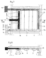
- FIGS. 7 and 8 show a second variant for the integration of the Room air flow shown in the heat exchanger according to the invention.
- Analogous to the previous embodiment is in a first installation duct 11a the entire installation for guiding the heat medium housed, namely Flow line 9 and return line 10. These are described in the above Way with a central return 19, a central heating medium flow 20 and a central coolant flow 21 connected, again a Distributor 16 is provided, which the flow line 9 optionally with the central heating medium flow 20 or the central cooling medium flow 22 combines.
- a control valve 17 is integrated, the Return line 10 has a shut-off valve 18.
- the second installation duct 11b which is not used for the heat medium guidance is used in this embodiment to guide the exhaust air.
- To the Installation duct 11b is connected to an exhaust duct 24, which Has passage openings 25.
- the through the openings 25 in the Exhaust air duct 24 received exhaust air 14 is via the installation duct 11b fed into a central exhaust air system and for example via corridors or derived other parts of the building.
- the supply air 13 to be supplied to the room is shown in this embodiment via a between the installation channels 11a and 11b located, central branch duct 23 and through a Heat exchanger plate 3a, which in turn has air passage slots 15 given the room.
- the supply air is already preheated or cooled.
- FIGS. 5 to 8 for a combination draw the heat exchanger according to the invention with a room air system stand out due to high economic efficiency as a result of the effective use of energy out.
- the system shown can be designed decoratively.
- the Number of heat exchanger plates 3 is free in this system as required selectable, it can up to the maximum capacity of the ceiling any number of heat exchanger plates 3 along the installation channels 11a or 11b can be arranged.
- the heat exchanger plates 3 and 3a are advantageously around a longitudinal axis lying transversely to the installation ducts 11a, 11b can be folded down, so that easy cleaning or maintenance work on the in the Installation channels located installations can take place.
Landscapes
- Engineering & Computer Science (AREA)
- Physics & Mathematics (AREA)
- Thermal Sciences (AREA)
- Chemical & Material Sciences (AREA)
- Combustion & Propulsion (AREA)
- Mechanical Engineering (AREA)
- General Engineering & Computer Science (AREA)
- Cooling Or The Like Of Electrical Apparatus (AREA)
- Domestic Hot-Water Supply Systems And Details Of Heating Systems (AREA)
- Heat-Exchange Devices With Radiators And Conduit Assemblies (AREA)
Applications Claiming Priority (2)
| Application Number | Priority Date | Filing Date | Title |
|---|---|---|---|
| DE20105068U DE20105068U1 (de) | 2001-03-23 | 2001-03-23 | Aufbau für einen Wärmetauscher |
| DE20105068U | 2001-03-23 |
Publications (2)
| Publication Number | Publication Date |
|---|---|
| EP1243861A2 true EP1243861A2 (fr) | 2002-09-25 |
| EP1243861A3 EP1243861A3 (fr) | 2003-06-11 |
Family
ID=7954731
Family Applications (1)
| Application Number | Title | Priority Date | Filing Date |
|---|---|---|---|
| EP02005011A Withdrawn EP1243861A3 (fr) | 2001-03-23 | 2002-03-06 | Construction d'un echangeur de chaleur |
Country Status (2)
| Country | Link |
|---|---|
| EP (1) | EP1243861A3 (fr) |
| DE (1) | DE20105068U1 (fr) |
Cited By (2)
| Publication number | Priority date | Publication date | Assignee | Title |
|---|---|---|---|---|
| EP1306624A3 (fr) * | 2001-10-26 | 2005-01-19 | Axel Dr. Jahn | Dispositif de chauffage et/ou de refrigeration à grande surface |
| CN110998213A (zh) * | 2017-07-27 | 2020-04-10 | 福迪斯流体动力有限公司 | 热交换设备 |
Family Cites Families (6)
| Publication number | Priority date | Publication date | Assignee | Title |
|---|---|---|---|---|
| US2751198A (en) * | 1951-01-05 | 1956-06-19 | Houdaille Industries Inc | Ceiling plenum and air conditioning system |
| US2701998A (en) * | 1952-03-26 | 1955-02-15 | Pyle National Co | Ventilating apparatus |
| EP0051713B1 (fr) * | 1980-11-12 | 1986-10-15 | Heinz Eggert | Chauffage mural à basse température |
| DE4020709A1 (de) * | 1990-06-29 | 1992-01-02 | Gravivent Raumlufttechnik Gmbh | Vorrichtung zum kuehlen oder heizen eines raumes |
| GB9220888D0 (en) * | 1992-10-05 | 1992-11-18 | Ingram Rex A | Improvements to heating/cooling systems |
| FR2800852B1 (fr) * | 1999-11-08 | 2001-12-21 | Pierre Edouard Sainsily | Dispositif de chauffage par le plafond |
-
2001
- 2001-03-23 DE DE20105068U patent/DE20105068U1/de not_active Expired - Lifetime
-
2002
- 2002-03-06 EP EP02005011A patent/EP1243861A3/fr not_active Withdrawn
Cited By (2)
| Publication number | Priority date | Publication date | Assignee | Title |
|---|---|---|---|---|
| EP1306624A3 (fr) * | 2001-10-26 | 2005-01-19 | Axel Dr. Jahn | Dispositif de chauffage et/ou de refrigeration à grande surface |
| CN110998213A (zh) * | 2017-07-27 | 2020-04-10 | 福迪斯流体动力有限公司 | 热交换设备 |
Also Published As
| Publication number | Publication date |
|---|---|
| DE20105068U1 (de) | 2001-06-07 |
| EP1243861A3 (fr) | 2003-06-11 |
Similar Documents
| Publication | Publication Date | Title |
|---|---|---|
| DE3874344T2 (de) | Verfahren zur lueftung und lueftungsanlage. | |
| DE68914246T2 (de) | Vorgefertigte Elemente für Klimatisation durch Strahlung oder Strahlung/Ventilation und eine diese Elemente enthaltende Klimaanlage. | |
| EP1170553B1 (fr) | Plafond réfrigerant | |
| EP1980679A2 (fr) | Mur extérieur d'un immeuble d'une construction murale en briques et procédé de fabrication des briques | |
| DE3312998A1 (de) | Gebaeudefassade zur nutzung der solarenergie | |
| DE102013109702A1 (de) | Luftauslass sowie Verfahren zu dessen Umrüstung | |
| DE19831918C2 (de) | Verfahren und Einrichtung zum Heizen oder Kühlen von vorwiegend geschlossenen Räumen | |
| EP1243861A2 (fr) | Construction d'un echangeur de chaleur | |
| DE102013114085A1 (de) | Lüftungsgerät zur Raumlüftung | |
| DE3030536C2 (de) | Brüstungselement zum Einbau in Fassaden | |
| EP2161512B1 (fr) | Appareil d'aération décentralisé et installation d'aération dotée d'un tel appareil | |
| DE1918446A1 (de) | Beheizbarer Fussboden | |
| EP3477212B1 (fr) | Dispositif de distribution d'air ainsi que procédé d'aération d'une pièce | |
| DE2537695C2 (de) | Flächenheizung für Fußböden oder Decken | |
| EP0374527A2 (fr) | Système de distribution d'air | |
| DE9218498U1 (de) | Vorrichtung zum Bräunen des menschlichen Körpers | |
| DE2218716C2 (de) | Verfahren zum Heizen oder Kühlen eines Raumes | |
| DE19712744C1 (de) | Raumtemperierungssystem | |
| DE69525672T2 (de) | Gebäudekonstruktionen und Verfahren zur Temperatursteuerung des Innenraums solcher Gebäude | |
| DE19738172C1 (de) | Einrichtung zum Temperieren von Gebäuden | |
| DE2110781A1 (de) | Vorrichtung zum Heizen oder Kuehlen von Raeumen | |
| DE3207372A1 (de) | Verteileraggregat fuer mit einem stroemungsfaehigen waermetraegermedium arbeitende heizungs- und/oder kuehlanlagen | |
| EP1568958A1 (fr) | Echangeur de chaleur | |
| DE202017106937U1 (de) | Decken- und/oder Wandverkleidung und Gebäude hiermit | |
| DE3023531A1 (de) | Vorrichtung zum beheizen, kuehlen und lueften von raeumen |
Legal Events
| Date | Code | Title | Description |
|---|---|---|---|
| PUAI | Public reference made under article 153(3) epc to a published international application that has entered the european phase |
Free format text: ORIGINAL CODE: 0009012 |
|
| AK | Designated contracting states |
Kind code of ref document: A2 Designated state(s): AT BE CH CY DE DK ES FI FR GB GR IE IT LI LU MC NL PT SE TR |
|
| AX | Request for extension of the european patent |
Free format text: AL;LT;LV;MK;RO;SI |
|
| PUAL | Search report despatched |
Free format text: ORIGINAL CODE: 0009013 |
|
| AK | Designated contracting states |
Designated state(s): AT BE CH CY DE DK ES FI FR GB GR IE IT LI LU MC NL PT SE TR |
|
| AX | Request for extension of the european patent |
Extension state: AL LT LV MK RO SI |
|
| RIC1 | Information provided on ipc code assigned before grant |
Ipc: 7F 24F 13/068 B Ipc: 7F 24F 7/10 B Ipc: 7F 24D 3/16 A |
|
| 17P | Request for examination filed |
Effective date: 20031127 |
|
| AKX | Designation fees paid |
Designated state(s): AT BE CH CY DE DK ES FI FR GB GR IE IT LI LU MC NL PT SE TR |
|
| RAP1 | Party data changed (applicant data changed or rights of an application transferred) |
Owner name: ZEHNDER VERKAUFS- UND VERWALTUNGS AG |
|
| GRAP | Despatch of communication of intention to grant a patent |
Free format text: ORIGINAL CODE: EPIDOSNIGR1 |
|
| GRAC | Information related to communication of intention to grant a patent modified |
Free format text: ORIGINAL CODE: EPIDOSCIGR1 |
|
| STAA | Information on the status of an ep patent application or granted ep patent |
Free format text: STATUS: THE APPLICATION IS DEEMED TO BE WITHDRAWN |
|
| 18D | Application deemed to be withdrawn |
Effective date: 20110212 |