EP1243945B1 - Sensor zur Objekterkennung - Google Patents
Sensor zur Objekterkennung Download PDFInfo
- Publication number
- EP1243945B1 EP1243945B1 EP02251246A EP02251246A EP1243945B1 EP 1243945 B1 EP1243945 B1 EP 1243945B1 EP 02251246 A EP02251246 A EP 02251246A EP 02251246 A EP02251246 A EP 02251246A EP 1243945 B1 EP1243945 B1 EP 1243945B1
- Authority
- EP
- European Patent Office
- Prior art keywords
- space
- image
- object detection
- distance
- image pickup
- Prior art date
- Legal status (The legal status is an assumption and is not a legal conclusion. Google has not performed a legal analysis and makes no representation as to the accuracy of the status listed.)
- Expired - Lifetime
Links
Images



Classifications
-
- G—PHYSICS
- G01—MEASURING; TESTING
- G01V—GEOPHYSICS; GRAVITATIONAL MEASUREMENTS; DETECTING MASSES OR OBJECTS; TAGS
- G01V8/00—Prospecting or detecting by optical means
- G01V8/10—Detecting, e.g. by using light barriers
-
- G—PHYSICS
- G08—SIGNALLING
- G08B—SIGNALLING SYSTEMS, e.g. PERSONAL CALLING SYSTEMS; ORDER TELEGRAPHS; ALARM SYSTEMS
- G08B13/00—Burglar, theft or intruder alarms
- G08B13/18—Actuation by interference with heat, light, or radiation of shorter wavelength; Actuation by intruding sources of heat, light, or radiation of shorter wavelength
- G08B13/181—Actuation by interference with heat, light, or radiation of shorter wavelength; Actuation by intruding sources of heat, light, or radiation of shorter wavelength using active radiation detection systems
Definitions
- the present invention relates to an object detection sensor which can be used as an automatic door sensor and the like.
- the present invention is concerned with measures to increase the degree of freedom in the setting of a detection area.
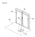
- Japanese Patent Laid-open Publication No. H7-229972 discloses an active infrared sensor, as shown in Fig. 10 , which is equipped with a transmitter and a receiver.
- this infrared sensor 101 while the transmitter emits infrared light toward a predetermined detection area 102 (defined by a chain-dotted line in Fig. 10 ), the light is reflected and received by the receiver. If a person or like object enters the detection area 102, the receiver receives the infrared light in a different state.
- the sensor 101 detects this change as approach of an object to an automatic door 103.
- the sensor 101 sends an object detection signal to an automatic door controller (not shown), so that the automatic door controller starts a door driving source (a driving motor) to open the automatic door 103.
- detection of objects may be partially unnecessary in the detection area 102.
- a no-detection area is provided by masking.
- the detection area 102 in Fig. 10 has a near-square contour as viewed in plan view.
- a shaded area 104 on the floor can be masked by emitting no infrared light toward the mask area 104.
- the light reflected in the mask area 104 may be cancelled in a signal processing.
- Another type of automatic door sensor is an image sensor which is equipped with a camera having a built-in image pickup element (e.g. CCD).
- This image sensor utilizes the camera to take an image of a detection area, and, based on the image information, judges the presence or absence of an object in the detection area.
- the detection area may include a part where detection of objects is not required (a mask area).
- the mask area can be obtained by taking no image of the mask area or by cancelling the image of the mask area in a signal processing.
- a mask space 105 is created over the area 104 (as defined by dashed lines).
- setting of the mask area 104 is inevitably accompanied with a mask space 105 which assumes the contour of a substantially quadrangular pyramid with the base of the mask area 104.
- the contour of the mask space 105 depends on the position of the infrared sensor 101 (the sensor in Fig. 10 is mounted on the transom) as well as the position and contour of the mask area 104.
- the infrared sensor sets the detection area 102 on the floor to have a depth E (the sidewise dimension in the drawing), in an attempt to detect a person or the like that enters the range of the depth E.
- the detection sensitivity is low along the end of the detection area 102 (e.g. the area indicated as the depth E1 in the drawing).
- the depth of the detection area 102 on the floor is generally set greater than the required depth E, as far as the depth E2 in the drawing.
- a sensor 106 may detect an object which is present at the outside of the required detection area (the range of the depth E), which causes misoperation of the automatic door.
- the detection object is a person passing on a pavement
- the depth E corresponds to the pavement.
- a driveway is adjacent to the outside of the depth E.
- the sensor 106 detects a vehicle 107 travelling on the driveway, and unnecessarily opens the door whenever a vehicle 107 passes through the detection area 102.
- An object of the present invention is to provide an object detection sensor which is capable of setting an optional detection area and preventing improper detection.
- the present invention takes an image of a detection area by image pickup means such as a CCD camera.
- image pickup means such as a CCD camera.
- the distance to an object is calculated.
- the sensor Based on the calculated distance, the sensor detects the three-dimensional position of the object in the image space, and compares the detected position with an object detection space which is registered in advance. Through this process, the sensor identifies the presence or absence of an object within the object detection space.
- the object detection space can be set in an optional three-dimensional contour.
- An object detection sensor corresponding to claim 1 (hereinafter mentioned as Invention 1) is equipped with image taking means, distance calculation means, position detection means, detection space registration means, judgement means and output means.
- the image taking means is capable of taking an image of a predetermined image space.
- the distance calculation means calculates a distance between the image pickup means and an object observed in the image of the image space, on receiving an output from the image pickup means.
- the position detection means detects a three-dimensional position of an object in the image space, on receiving an output from the distance calculation means. In this position detection means, the position of an object is detected with respect to the object for which the distance from the image taking means is calculated, based on the calculated distance.
- the detection space registration means is capable of setting an optional mask space in the image space which is covered by the image taking means.
- This detection space registration means registers a space in the image space, excluding the mask space, as an object detection space.
- the judgement means judges whether the detected three-dimensional position of the object locates within or outside the registered object detection space, on receiving outputs from the position detection means and the detection space registration means.
- the output means outputs an object detection signal, on receiving an output from the judgement means. This object detection signal is produced, with a proviso that the detected three-dimensional position of the object locates within the registered object detection space.
- An object detection sensor corresponding to claim 2 adopts a different type of detection space registration means.
- This detection space registration means registers, as an object detection space, an optional space in the image space which is covered by the image taking means.
- the distance calculation means calculates the distance between the image pickup means and an object observed within the image. Based on the information, the position detection means detects the three-dimensional position of the object.
- the detection space registration means registers an object detection space which is set in an optional three-dimensional contour by a user. The judgement means judges whether the detected three-dimensional position of the object locates within or outside the registered object detection space. If the object is present within the object detection space, the output means produces an object detection signal. For example, where this object detection sensor is applied to an automatic door, the door is made open in response to the detection of an object.
- An object detection sensor corresponding to claim 3 (hereinafter mentioned as Invention 3) is featured by a specific manner of setting the object detection space which is registered in the detection space registration means. Namely, the image space covered by the image pickup means is divided into a plurality of space elements in a cubic lattice pattern. As the object detection space, the detection space registration means registers a space which is composed of a part of these space elements.
- a user can optionally set the three-dimensional coordinates of space elements which correspond to an object detection space, considering which of the space elements in the image space should constitute to the object detection space.
- the object detection space in an optional contour, simply by setting the coordinates of some space elements.
- an object detection sensor corresponding to claim 4 (hereinafter mentioned as Invention 4) is featured by a specific operation of the output means for producing the object detection signal.
- this object detection sensor is installed as a sensor for an automatic door and associated with means for controlling an open/close drive of the door along the track.
- the output means is arranged to be capable of outputting the object detection signal to the door drive control means, such that the object detection signal outputted to the door drive control means causes the door to open fully.
- the detection area around the door can be set in an optional contour.
- the object detection sensor can avoid improper detection and thereby improve the reliability in the opening/closing action of the automatic door.
- object detection sensors corresponding to claim 5 and claim 6 are featured by specific operations of the distance calculation means for calculating the distance between the image pickup means and the object.
- the sensor of Invention 5 employs image pickup means which has a plurality of image pickup elements.
- the distance calculation means calculates the distance between the image pickup means and the object by stereo image processing which utilizes parallax of images taken by these image pickup elements.
- the sensor of Invention 6 employs image pickup means which has a variable focus lens.
- the distance calculation means calculates the distance between the image pickup means and the object, based on the degree of focus on the object which is observed in the image taken by the image pickup means.
- the sensor of Invention 6 can simplify the structure of the image pickup means, because it requires no more than one image pickup element.
- the object detection sensor according to the present invention is applied as an automatic door sensor.
- Fig. 1 is a perspective view showing an automatic door and around a doorway of the automatic door, concerning this embodiment.
- the automatic door used in this embodiment is a bi-parting door which has two door segments 1, 1 movable in opening/closing directions (movable in horizontal directions) along a track at a doorway 2.
- a detection area 10 an object detection space
- the three-dimensional detection area is defined by chain-dotted lines in the drawing.
- This signal is sent to an automatic door controller 5 (door drive control means) housed in a transom 4.
- the automatic door controller 5 On receiving the object detection signal, the automatic door controller 5 starts a driving motor of a door opening/closing mechanism (not shown) and thereby opens the door segments 1, 1. Since the opening/closing mechanism of the door segments 1, 1 is well known in the art, its description is omitted herein.
- Fig. 2 is a block diagram showing the general constitution of the automatic door sensor 3.
- the sensor 3 is composed of two cameras 31, 32 (each having a built-in image pickup element such as CCD) as image pickup means, a distance calculation unit 33 as distance calculation means, a coordinate transformation unit 34 as position detection means, an area registration unit 35 as detection space registration means, a judgement unit 36 as judgement means, and an output unit 37 as output means.
- the cameras 31, 32 are contained in a sensor casing 3A, with their optical axes oriented parallel to each other.
- the sensor casing 3A is mounted on the transom 4, such that image pickup directions of the cameras 31, 32 are oriented at predetermined elevation angles relative to the vertically downward direction.
- each of the cameras 31, 32 can take an image of a prescribed image space around the door segments 1, 1.
- the distance calculation unit 33 receives information which relates to images taken by the cameras 31, 32. Then, the unit 33 calculates the distance between the cameras 31, 32 and an object in the images, by so-called stereo image processing. To be specific, between the image taken by the camera 31 and the image taken by the camera 32, the unit 33 measures displacement (i.e. "parallax") of an object observed in both images.
- the object for which the distance K from the cameras 31, 32 is calculated encompasses all objects which are present in the above-defined image space, including a floor as well as a person and like object.
- the distance between the cameras 31, 32 and an object is calculated as the distance of a straight line which extends orthogonally to the plane L in Fig. 3 (the plane L is a plane orthogonal to the image pickup direction of the cameras 31, 32), namely, as a linear distance parallel to the image pickup direction of the cameras 31, 32.
- the distance from the cameras 31, 32 to the floor 6 is calculated as L1.
- the distance from the cameras 31, 32 to the object 7 is calculated as L2.
- the distance calculated by the foregoing computation is corrected by a trigonometric function. In some cases, the calculated distance can be directly used as the actual distance without a significant error. Then, it is possible to omit the distance correction and go to the next process.
- the coordinate transformation unit 34 receives an output from the distance calculation unit 33. Then, with respect to the object for which the distance from the cameras 31, 32 is calculated, the unit 34 detects its three-dimensional position in the image space, based on the calculated distance, and thereby determines the position coordinates of the object. Specifically, the coordinate transformation unit 34 sets the approximate center of the door track on the floor 6 (the point P1 in Fig. 3 ) as the origin (0, 0, 0) of the three-dimensional coordinates. Taking the origin as a reference, the unit 34 is set to represent the position of the object in the taken images, in terms of three-dimensional coordinates. Incidentally, the point P1 on the floor 6 is detected in the following manner.
- the unit 34 recognizes, as the floor 6, an object which locates vertically under the cameras 31, 32.
- the distance calculation unit 33 calculates the distance to an object which lies vertically under the cameras 31, 32, and also detects a point which locates vertically thereunder in the images. The detected point is to be recognized as the point P1.
- the coordinate transformation unit 34 recognizes the positional relationship between the cameras 31, 32 and the floor 6, such as the mounting height and position of the cameras 31, 32 relative to the floor 6 (i.e.
- the point P1 is set as the origin (0, 0, 0) of the three-dimensional coordinates, so that the position of the object in the taken images can be represented by three-dimensional coordinates.
- the area registration unit 35 sets a certain mask space in the image space which is covered by the cameras 31, 32.
- An object detection space (the detection area 10) is defined as the space in the image space except the mask space, and registered in the unit 35 as such.
- the setting of the mask space is detailed below.
- the image space of which the cameras 31, 32 can take images is divided into a plurality of space elements in a cubic lattice pattern (hereinafter, these space elements are to be called voxels).
- Fig. 4 is a perspective view showing the image space (the space having a contour of a substantially quadrangular pyramid) which is divided into voxels. Each of the voxels is allotted with three-dimensional coordinates. Referring to Fig.
- the voxel at the point P1 has coordinates (0, 0, 0) ; the voxel at P2 has coordinates (9, 0, 0); the voxel at P3 has coordinates (9, 9, 0); and the voxel at P4 has coordinates (-9, 9, 0), to give a few example.
- a user sets a mask space by designating the voxels which locate within the space to be masked. Thereafter, the voxels in the mask space are excluded from the whole voxels on the three-dimensional coordinates, so that the voxels locating within the detection area 10 (the object detection space) can be determined.
- This object detection space is set, for example, by means of a personal computer 8 which is connected with the automatic door sensor 3. While an operator checks each voxel on a display device 81 (display) of the personal computer 8, he/she sets the object detection space by a setting device 82 (an input device such as a keyboard).
- the coordinates of the voxels shown in Fig. 5(b) are excluded from those of the whole voxels within the image space (see Fig. 4 ).
- the coordinates of the voxels locating in the detection area 10 are determined as those of the voxels shown in Fig. 5(a) .
- the judgement unit 36 receives outputs from the coordinate transformation unit 34 and the area registration unit 35, and judges whether the detected position of the object locates within or outside the registered detection area 10.
- the output unit 37 receives an output from the judgement unit 36. Then, the unit 37 outputs an object detection signal to the automatic door controller 5, if the detected position of the object is within the registered detection area 10. In response to this signal, the automatic door controller 5 controls the driving motor of the door opening/closing mechanism to open the door segments 1, 1.
- the distance calculation unit 33 calculates the distance to an object which is present vertically under the cameras 31, 32, based on the image information from the cameras 31, 32. In addition, the unit 33 detects a point which locates vertically under the cameras 31, 32 in the images. The coordinates of the voxel at the point P1 are set to (0, 0, 0).
- the cameras 31, 32 take images of the detection area 10 at fixed time intervals. Information on the taken images is sent to the distance calculation unit 33, where the distance between the cameras 31, 32 and an object in the images taken by the cameras 31, 32 is calculated by the stereo image processing of these images as detailed above.
- the data on the calculated distance to each object is sent to the coordinate transformation unit 34.
- the coordinate transformation unit 34 Based on the calculated distance, the coordinate transformation unit 34 detects the three-dimensional position of the object for which the distance from the cameras 31, 32 is calculated, thereby determining the position coordinates of this object.
- the judgement unit 36 receives outputs from the coordinate transformation unit 34 and the area registration unit 35. Then, the unit 36 judges whether the detected position of the object locates within or outside the registered detection area 10. If the presence of a person or like object is recognized in the detection area 10, a judgement signal is transmitted from the judgement unit 36 to the output unit 37. In response to this signal, the output unit 37 outputs an object detection signal to the automatic door controller 5. On receiving the object detection signal, the automatic door controller 5 keeps the door segments 1, 1 in the open state or opens the closing or closed door segments 1, 1.
- the sensor calculates the distance between the cameras 31, 32 and an object observed in the images. Based on the information, the sensor detects the three-dimensional coordinates of the object. Then, the sensor compares the three-dimensional coordinates of the object with the detection area 10 which is registered in advance. If the object locates within the detection area 10, the door segments 1, 1 are allowed to open.
- the detection area 10 can be set in an optional contour by dividing the image space into a plurality of voxels and setting optional voxels as the mask space. The effect of this structure can be particularly understood in the case where a pavement 91 and a driveway 92 are adjacent as illustrated in Fig. 6 .
- a no-detection area 20 is set as the mask area (the shaded area in the drawing). As a result, the sensor can prevent unnecessary detection of a vehicle 93 and consequential misoperation of the automatic door, while maintaining a good detection sensitivity to a person passing on the pavement 91 (i.e. exhibit a high detection sensitivity over the entire pavement 91).
- the distance between the cameras 31, 32 and an object can be measured in a different manner.
- the image pickup means is constituted with a camera having a variable focus lens.
- the image information is sent to the distance calculation unit 33.
- the distance calculation unit 33 calculates the distance to the object, based on the degree of focus on the object which is observed in the image taken by the camera.
- the automatic door sensor 3 is mounted in various situations.
- Fig. 7 shows the sensor 3 mounted near a stairway 71.
- a fixed object 72 which need not be detected is installed in the image space.
- the mask space 20 is set in conformity with the contour of the stairway 71 in order that voxels within the mask space 20 are excluded from the detection area 10.
- the mask space 20 is set along the contour of the fixed object 72 in order that voxels within the mask space 20 are excluded from the detection area 10.
- the automatic door sensor 3 according to the present invention is applied as an activation sensor, but the present invention should not be limited to such application. Additionally, this automatic door sensor can combine the functions of an activation sensor and a safety sensor, by extending the region to be covered by the cameras 31, 32.
- the sensor shown in Fig. 9 (a view equivalent to Fig. 1 ) has an extended image pickup region which is large enough to combine the functions of an activation sensor and a safety sensor.
- the automatic door sensor 3 serves as the activation sensor, in which the detection area 10 excludes the door with the intention of avoiding misoperation.
- a safety sensor is mounted on the posts such that its detection area covers the door rail and its vicinity.
- a detection area 11 of the automatic sensor 3 covers the door, thus including the area on and over the door rail.
- This sensor can achieve the functions of an activation sensor and a safety sensor in combination, without placing a separate safety sensor.
- the present invention is applicable not only to bi-parting automatic doors, as in the above embodiments, but also to single-sliding automatic doors.
- the present invention divides the image space into voxels. Additionally, the present invention can be arranged to set the detection area 10 in an optional contour in alternative manners.
Landscapes
- Physics & Mathematics (AREA)
- General Physics & Mathematics (AREA)
- Life Sciences & Earth Sciences (AREA)
- General Life Sciences & Earth Sciences (AREA)
- Geophysics (AREA)
- Length Measuring Devices By Optical Means (AREA)
- Power-Operated Mechanisms For Wings (AREA)
- Geophysics And Detection Of Objects (AREA)
- Measurement Of Optical Distance (AREA)
Claims (6)
- Sensor zur Objekterkennung, welcher umfasst:ein Mittel, das geeignet ist, ein Bild eines vorbestimmten Bildraums aufzunehmen;ein Mittel zur Berechnung eines Abstands zwischen dem Bildaufnahmemittel und einem im Bild des Bildraums beobachteten Objekt, wobei das Abstandsberechnungsmittel auf Empfang einer Ausgangsgröße vom Bildaufnahmemittel arbeitet;eine Koordinatentransformationseinheit zur Erkennung einer dreidimensionalen Position eines Objekts im Bildraum und zur Bestimmung der Positionskoordinaten des Objekts, wobei die Koordinatentransformationseinheit auf Empfang einer Ausgangsgröße vom Abstandsberechnungsmittel arbeitet, und wobei die Position des Objekts bezüglich des Objekts, für welches der Abstand vom Bildaufnahmemittel berechnet wird, auf der Basis des berechneten Abstands erkannt wird;ein Mittel zur Registrierung eines Erkennungsraums, welches einen optionalen Raum im vom Bildaufnahmemittel abgedeckten Bildraum als Objekterkennungsraum registriert;ein Mittel zur Beurteilung, ob die erfasste dreidimensionale Position des Objekts innerhalb oder außerhalb des registrierten Objekterkennungsraum liegt, wobei das Beurteilungsmittel auf Empfang von Ausgangsgrößen von der Koordinatentransformationseinheit und vom Erkennungsraum-Registriermittel arbeitet; undein Mittel zur Ausgabe eines Objekterkennungssignals, wobei das Ausgabemittel auf Empfang einer Ausgangsgröße vom Beurteilungsmittel arbeitet, und wobei das Objekterkennungssignal unter der Bedingung ausgegeben wird, dass die erkannte dreidimensionale Position des Objekts innerhalb des registrierten Objekterkennungsraums liegt.
- Sensor zur Objekterkennung nach Anspruch 1,
dadurch gekennzeichnet, dass das Erkennungsraum-Registriermittel geeignet ist, einen optionalen Maskenraum in dem vom Bildaufnahmemittel abgedeckten Bildraum festzulegen und einen Raum im Bildraum unter Ausschluss des Maskenraums als Objekterkennungsraum zu registrieren. - Sensor zur Objekterkennung nach Anspruch 1 oder 2,
dadurch gekennzeichnet, dass der vom Bildaufnahmemittel abgedeckte Bildraum in eine Mehrzahl von Raumelementen nach einem kubischen Gittermuster aufgeteilt ist,
und dass das Erkennungsraum-Registriermittel als Objekterkennungsraum einen Raum registriert, welcher aus einem Teil der Raumelemente besteht. - Sensor zur Objekterkennung nach Anspruch 1, 2 oder 3,
welcher als Sensor für eine automatische Tür installiert ist,
dadurch gekennzeichnet, dass der Sensor mit Mitteln zur Steuerung eines Öffnungs- und Schließantriebs der Tür entlang einer Führungsbahn assoziiert ist,
und dass das Ausgabemittel geeignet ist, das Objekterkennungssignal an das Türantriebs-Steuermittel auszugeben, so dass das an das Türantriebs-Steuermittel ausgegebene Objekterkennungssignal die vollständige Öffnung der Tür bewirkt. - Sensor zur Objekterkennung nach einem der Ansprüche 1 bis 4,
dadurch gekennzeichnet, dass das Bildaufnahmemittel eine Mehrzahl von Bildaufnahmeelementen aufweist,
und dass das Abstandsberechnungsmittel den Abstand zwischen dem Bildaufnahmemittel und dem Objekt durch Stereo-Bildbearbeitung berechnet, welche die Parallaxe der von diesen Bildaufnahmemitteln aufgenommenen Bildern verwendet. - Sensor zur Objekterkennung nach einem der Ansprüche 1 bis 4,
dadurch gekennzeichnet, dass das Bildaufnahmemittel ein Objektiv mit variabler Brennweite aufweist,
und dass das Abstandsberechnungsmittel den Abstand zwischen dem Bildaufnahmemittel und dem Objekt berechnet auf der Basis der Brennweite zur Scharfeinstellung des Objekts, welches im vom Bildaufnahmemittel aufgenommenen Bild beobachtet wird.
Applications Claiming Priority (2)
| Application Number | Priority Date | Filing Date | Title |
|---|---|---|---|
| JP2001051503 | 2001-02-27 | ||
| JP2001051503A JP2002250607A (ja) | 2001-02-27 | 2001-02-27 | 物体検知センサ |
Publications (3)
| Publication Number | Publication Date |
|---|---|
| EP1243945A2 EP1243945A2 (de) | 2002-09-25 |
| EP1243945A3 EP1243945A3 (de) | 2003-05-28 |
| EP1243945B1 true EP1243945B1 (de) | 2009-01-21 |
Family
ID=18912276
Family Applications (1)
| Application Number | Title | Priority Date | Filing Date |
|---|---|---|---|
| EP02251246A Expired - Lifetime EP1243945B1 (de) | 2001-02-27 | 2002-02-22 | Sensor zur Objekterkennung |
Country Status (5)
| Country | Link |
|---|---|
| US (1) | US6791461B2 (de) |
| EP (1) | EP1243945B1 (de) |
| JP (1) | JP2002250607A (de) |
| AT (1) | ATE421704T1 (de) |
| DE (1) | DE60230941D1 (de) |
Cited By (41)
| Publication number | Priority date | Publication date | Assignee | Title |
|---|---|---|---|---|
| US9057779B2 (en) | 2011-04-01 | 2015-06-16 | Cedes Ag | Sensor device, safety device, door and method for monitoring the movement |
| US10019816B2 (en) | 2011-09-28 | 2018-07-10 | Fotonation Cayman Limited | Systems and methods for decoding image files containing depth maps stored as metadata |
| US10091405B2 (en) | 2013-03-14 | 2018-10-02 | Fotonation Cayman Limited | Systems and methods for reducing motion blur in images or video in ultra low light with array cameras |
| US10089740B2 (en) | 2014-03-07 | 2018-10-02 | Fotonation Limited | System and methods for depth regularization and semiautomatic interactive matting using RGB-D images |
| US10119808B2 (en) | 2013-11-18 | 2018-11-06 | Fotonation Limited | Systems and methods for estimating depth from projected texture using camera arrays |
| US10127682B2 (en) | 2013-03-13 | 2018-11-13 | Fotonation Limited | System and methods for calibration of an array camera |
| US10182216B2 (en) | 2013-03-15 | 2019-01-15 | Fotonation Limited | Extended color processing on pelican array cameras |
| US10225543B2 (en) | 2013-03-10 | 2019-03-05 | Fotonation Limited | System and methods for calibration of an array camera |
| US10250871B2 (en) | 2014-09-29 | 2019-04-02 | Fotonation Limited | Systems and methods for dynamic calibration of array cameras |
| US10261219B2 (en) | 2012-06-30 | 2019-04-16 | Fotonation Limited | Systems and methods for manufacturing camera modules using active alignment of lens stack arrays and sensors |
| US10306120B2 (en) | 2009-11-20 | 2019-05-28 | Fotonation Limited | Capturing and processing of images captured by camera arrays incorporating cameras with telephoto and conventional lenses to generate depth maps |
| US10311649B2 (en) | 2012-02-21 | 2019-06-04 | Fotonation Limited | Systems and method for performing depth based image editing |
| US10334241B2 (en) | 2012-06-28 | 2019-06-25 | Fotonation Limited | Systems and methods for detecting defective camera arrays and optic arrays |
| US10366472B2 (en) | 2010-12-14 | 2019-07-30 | Fotonation Limited | Systems and methods for synthesizing high resolution images using images captured by an array of independently controllable imagers |
| US10375302B2 (en) | 2011-09-19 | 2019-08-06 | Fotonation Limited | Systems and methods for controlling aliasing in images captured by an array camera for use in super resolution processing using pixel apertures |
| US10380752B2 (en) | 2012-08-21 | 2019-08-13 | Fotonation Limited | Systems and methods for estimating depth and visibility from a reference viewpoint for pixels in a set of images captured from different viewpoints |
| US10390005B2 (en) | 2012-09-28 | 2019-08-20 | Fotonation Limited | Generating images from light fields utilizing virtual viewpoints |
| US10455218B2 (en) | 2013-03-15 | 2019-10-22 | Fotonation Limited | Systems and methods for estimating depth using stereo array cameras |
| US10462362B2 (en) | 2012-08-23 | 2019-10-29 | Fotonation Limited | Feature based high resolution motion estimation from low resolution images captured using an array source |
| US10542208B2 (en) | 2013-03-15 | 2020-01-21 | Fotonation Limited | Systems and methods for synthesizing high resolution images using image deconvolution based on motion and depth information |
| US10540806B2 (en) | 2013-09-27 | 2020-01-21 | Fotonation Limited | Systems and methods for depth-assisted perspective distortion correction |
| US10674138B2 (en) | 2013-03-15 | 2020-06-02 | Fotonation Limited | Autofocus system for a conventional camera that uses depth information from an array camera |
| US10708492B2 (en) | 2013-11-26 | 2020-07-07 | Fotonation Limited | Array camera configurations incorporating constituent array cameras and constituent cameras |
| US11270110B2 (en) | 2019-09-17 | 2022-03-08 | Boston Polarimetrics, Inc. | Systems and methods for surface modeling using polarization cues |
| US11290658B1 (en) | 2021-04-15 | 2022-03-29 | Boston Polarimetrics, Inc. | Systems and methods for camera exposure control |
| US11302012B2 (en) | 2019-11-30 | 2022-04-12 | Boston Polarimetrics, Inc. | Systems and methods for transparent object segmentation using polarization cues |
| US11412158B2 (en) | 2008-05-20 | 2022-08-09 | Fotonation Limited | Capturing and processing of images including occlusions focused on an image sensor by a lens stack array |
| US11525906B2 (en) | 2019-10-07 | 2022-12-13 | Intrinsic Innovation Llc | Systems and methods for augmentation of sensor systems and imaging systems with polarization |
| US11580667B2 (en) | 2020-01-29 | 2023-02-14 | Intrinsic Innovation Llc | Systems and methods for characterizing object pose detection and measurement systems |
| US11689813B2 (en) | 2021-07-01 | 2023-06-27 | Intrinsic Innovation Llc | Systems and methods for high dynamic range imaging using crossed polarizers |
| US11792538B2 (en) | 2008-05-20 | 2023-10-17 | Adeia Imaging Llc | Capturing and processing of images including occlusions focused on an image sensor by a lens stack array |
| US11797863B2 (en) | 2020-01-30 | 2023-10-24 | Intrinsic Innovation Llc | Systems and methods for synthesizing data for training statistical models on different imaging modalities including polarized images |
| US11954886B2 (en) | 2021-04-15 | 2024-04-09 | Intrinsic Innovation Llc | Systems and methods for six-degree of freedom pose estimation of deformable objects |
| US11953700B2 (en) | 2020-05-27 | 2024-04-09 | Intrinsic Innovation Llc | Multi-aperture polarization optical systems using beam splitters |
| US12020455B2 (en) | 2021-03-10 | 2024-06-25 | Intrinsic Innovation Llc | Systems and methods for high dynamic range image reconstruction |
| US12069227B2 (en) | 2021-03-10 | 2024-08-20 | Intrinsic Innovation Llc | Multi-modal and multi-spectral stereo camera arrays |
| US12067746B2 (en) | 2021-05-07 | 2024-08-20 | Intrinsic Innovation Llc | Systems and methods for using computer vision to pick up small objects |
| US12175741B2 (en) | 2021-06-22 | 2024-12-24 | Intrinsic Innovation Llc | Systems and methods for a vision guided end effector |
| US12172310B2 (en) | 2021-06-29 | 2024-12-24 | Intrinsic Innovation Llc | Systems and methods for picking objects using 3-D geometry and segmentation |
| US12293535B2 (en) | 2021-08-03 | 2025-05-06 | Intrinsic Innovation Llc | Systems and methods for training pose estimators in computer vision |
| US12340538B2 (en) | 2021-06-25 | 2025-06-24 | Intrinsic Innovation Llc | Systems and methods for generating and using visual datasets for training computer vision models |
Families Citing this family (32)
| Publication number | Priority date | Publication date | Assignee | Title |
|---|---|---|---|---|
| US6701005B1 (en) | 2000-04-29 | 2004-03-02 | Cognex Corporation | Method and apparatus for three-dimensional object segmentation |
| JP3811724B2 (ja) * | 2002-04-03 | 2006-08-23 | オプテックス株式会社 | 自動ドア開閉装置 |
| US7397929B2 (en) * | 2002-09-05 | 2008-07-08 | Cognex Technology And Investment Corporation | Method and apparatus for monitoring a passageway using 3D images |
| US7400744B2 (en) * | 2002-09-05 | 2008-07-15 | Cognex Technology And Investment Corporation | Stereo door sensor |
| US7920718B2 (en) * | 2002-09-05 | 2011-04-05 | Cognex Corporation | Multi-zone passageway monitoring system and method |
| US7123144B2 (en) * | 2003-04-23 | 2006-10-17 | Miller Edge, Inc. | Monitored transmitter and receiver system and method for safety devices |
| US7623674B2 (en) * | 2003-11-05 | 2009-11-24 | Cognex Technology And Investment Corporation | Method and system for enhanced portal security through stereoscopy |
| US8326084B1 (en) | 2003-11-05 | 2012-12-04 | Cognex Technology And Investment Corporation | System and method of auto-exposure control for image acquisition hardware using three dimensional information |
| JP4259419B2 (ja) * | 2004-07-30 | 2009-04-30 | パナソニック電工株式会社 | 人体検知センサ |
| CZ2004922A3 (cs) * | 2004-09-02 | 2006-04-12 | Vúkv A. S. | Dvere s pohonem s prímým lineárním elektrickým motorem hromadných dopravních prostredku, zejména kolejových |
| US20070047837A1 (en) * | 2005-08-29 | 2007-03-01 | John Schwab | Method and apparatus for detecting non-people objects in revolving doors |
| US8111904B2 (en) | 2005-10-07 | 2012-02-07 | Cognex Technology And Investment Corp. | Methods and apparatus for practical 3D vision system |
| US7490841B2 (en) * | 2006-01-31 | 2009-02-17 | Miller Edge, Inc. | Passenger detection system |
| US7986232B2 (en) * | 2006-08-03 | 2011-07-26 | Tyco Safety Products Canada Ltd. | Method and apparatus for using an infrared reflectivity sensor in a security system |
| WO2008037282A1 (en) * | 2006-09-28 | 2008-04-03 | B.E.A. S.A. | Sensor for presence detection |
| JP4970062B2 (ja) * | 2007-01-23 | 2012-07-04 | 三菱電機株式会社 | 監視制御装置 |
| US8126260B2 (en) * | 2007-05-29 | 2012-02-28 | Cognex Corporation | System and method for locating a three-dimensional object using machine vision |
| WO2008149923A1 (ja) * | 2007-06-07 | 2008-12-11 | The University Of Electro-Communications | 物体検出装置とそれを適用したゲート装置 |
| FR2925737B1 (fr) * | 2007-12-20 | 2015-01-23 | Onera (Off Nat Aerospatiale) | Installation de detection de personnes dans un espace delimite. |
| JP4650565B2 (ja) * | 2008-12-15 | 2011-03-16 | パナソニック電工株式会社 | 人体検知センサ |
| US8931216B2 (en) * | 2011-12-07 | 2015-01-13 | Propel Doors Llc | Automatic sliding door systems, apparatus and methods |
| FR2993509B1 (fr) * | 2012-07-17 | 2015-03-20 | Airbus | Dispositif electronique de protection contre l'eblouissement d'un pilote ou d'un conducteur. |
| JP6338421B2 (ja) * | 2014-03-31 | 2018-06-06 | キヤノン株式会社 | 情報処理装置、情報処理装置の制御方法、把持システムおよびプログラム |
| CN103967387B (zh) * | 2014-05-26 | 2016-03-30 | 南宁思飞电子科技有限公司 | 一种门禁装置 |
| DE102016201741A1 (de) * | 2016-02-04 | 2017-08-10 | Hella Kgaa Hueck & Co. | Verfahren zur Höhenerkennung |
| EP3236286B1 (de) * | 2016-04-18 | 2023-01-25 | Otis Elevator Company | Autokommissionierungssystem und -verfahren |
| JP6653920B2 (ja) * | 2017-09-22 | 2020-02-26 | オプテックス株式会社 | 自動ドアシステム |
| CN112352086B (zh) * | 2018-06-15 | 2022-05-06 | 亚萨合莱自动门系统有限公司 | 具有一个或多个可移动门构件的进入系统的配置 |
| KR102045871B1 (ko) * | 2019-06-07 | 2019-11-18 | 주식회사 창성에이스산업 | 인공지능 기술에 기반한 화재감지시스템 및 인공지능 기술에 기반한 화재감지방법 |
| US10977826B1 (en) * | 2019-12-17 | 2021-04-13 | Motorola Solutions, Inc. | Safety detection camera system for door closure |
| JP7679859B2 (ja) * | 2023-08-29 | 2025-05-20 | 三菱電機ビルソリューションズ株式会社 | 通行判定装置、入退管理システム、通行判定方法、入退管理方法、通行判定プログラム、および入退管理プログラム |
| US20250193507A1 (en) * | 2023-12-12 | 2025-06-12 | Microsoft Technology Licensing, Llc | User sensing dynamic camera resolution control |
Family Cites Families (12)
| Publication number | Priority date | Publication date | Assignee | Title |
|---|---|---|---|---|
| US5321767A (en) * | 1992-08-28 | 1994-06-14 | Kabushiki Kaisha Komatsu Seisakusho | Method of forming a mask in image processing operation |
| JPH07229972A (ja) | 1994-02-15 | 1995-08-29 | Sumitomo Metal Mining Co Ltd | 静止体検知自動ドア用センサ |
| JP2919284B2 (ja) * | 1994-02-23 | 1999-07-12 | 松下電工株式会社 | 物体認識方法 |
| JP3497929B2 (ja) * | 1995-09-29 | 2004-02-16 | 富士重工業株式会社 | 侵入物監視装置 |
| JP3689946B2 (ja) * | 1995-10-05 | 2005-08-31 | ソニー株式会社 | データ処理装置及び方法 |
| JPH09145318A (ja) * | 1995-11-16 | 1997-06-06 | Nikon Corp | 三次元計測装置 |
| JPH09245271A (ja) * | 1996-03-06 | 1997-09-19 | Atsumi Electron Corp Ltd | 物体検知システム |
| DE19700811A1 (de) * | 1997-01-13 | 1998-07-16 | Heinrich Landert | Verfahren und Vorrichtung zur Ansteuerung von Türanlage in Abhängigkeit von der Anwesenheit von Personen |
| US5917937A (en) * | 1997-04-15 | 1999-06-29 | Microsoft Corporation | Method for performing stereo matching to recover depths, colors and opacities of surface elements |
| GB2326710A (en) * | 1997-06-26 | 1998-12-30 | Memco Ltd | Door obstruction detector |
| JPH11257931A (ja) * | 1998-03-13 | 1999-09-24 | Matsushita Electric Ind Co Ltd | 物体認識装置 |
| JP2000155177A (ja) * | 1998-11-20 | 2000-06-06 | Nikon Corp | 人体検知装置および人体検知方法 |
-
2001
- 2001-02-27 JP JP2001051503A patent/JP2002250607A/ja active Pending
-
2002
- 2002-02-22 EP EP02251246A patent/EP1243945B1/de not_active Expired - Lifetime
- 2002-02-22 AT AT02251246T patent/ATE421704T1/de not_active IP Right Cessation
- 2002-02-22 DE DE60230941T patent/DE60230941D1/de not_active Expired - Lifetime
- 2002-02-27 US US10/083,480 patent/US6791461B2/en not_active Expired - Lifetime
Cited By (73)
| Publication number | Priority date | Publication date | Assignee | Title |
|---|---|---|---|---|
| US12041360B2 (en) | 2008-05-20 | 2024-07-16 | Adeia Imaging Llc | Capturing and processing of images including occlusions focused on an image sensor by a lens stack array |
| US11792538B2 (en) | 2008-05-20 | 2023-10-17 | Adeia Imaging Llc | Capturing and processing of images including occlusions focused on an image sensor by a lens stack array |
| US12563310B2 (en) | 2008-05-20 | 2026-02-24 | Adeia Imaging Llc | Capturing and processing of images including occlusions focused on an image sensor by a lens stack array |
| US11412158B2 (en) | 2008-05-20 | 2022-08-09 | Fotonation Limited | Capturing and processing of images including occlusions focused on an image sensor by a lens stack array |
| US12022207B2 (en) | 2008-05-20 | 2024-06-25 | Adeia Imaging Llc | Capturing and processing of images including occlusions focused on an image sensor by a lens stack array |
| US10306120B2 (en) | 2009-11-20 | 2019-05-28 | Fotonation Limited | Capturing and processing of images captured by camera arrays incorporating cameras with telephoto and conventional lenses to generate depth maps |
| US10366472B2 (en) | 2010-12-14 | 2019-07-30 | Fotonation Limited | Systems and methods for synthesizing high resolution images using images captured by an array of independently controllable imagers |
| US12243190B2 (en) | 2010-12-14 | 2025-03-04 | Adeia Imaging Llc | Systems and methods for synthesizing high resolution images using images captured by an array of independently controllable imagers |
| US11423513B2 (en) | 2010-12-14 | 2022-08-23 | Fotonation Limited | Systems and methods for synthesizing high resolution images using images captured by an array of independently controllable imagers |
| US11875475B2 (en) | 2010-12-14 | 2024-01-16 | Adeia Imaging Llc | Systems and methods for synthesizing high resolution images using images captured by an array of independently controllable imagers |
| US9057779B2 (en) | 2011-04-01 | 2015-06-16 | Cedes Ag | Sensor device, safety device, door and method for monitoring the movement |
| US10375302B2 (en) | 2011-09-19 | 2019-08-06 | Fotonation Limited | Systems and methods for controlling aliasing in images captured by an array camera for use in super resolution processing using pixel apertures |
| US11729365B2 (en) | 2011-09-28 | 2023-08-15 | Adela Imaging LLC | Systems and methods for encoding image files containing depth maps stored as metadata |
| US10984276B2 (en) | 2011-09-28 | 2021-04-20 | Fotonation Limited | Systems and methods for encoding image files containing depth maps stored as metadata |
| US20180197035A1 (en) | 2011-09-28 | 2018-07-12 | Fotonation Cayman Limited | Systems and Methods for Encoding Image Files Containing Depth Maps Stored as Metadata |
| US10275676B2 (en) | 2011-09-28 | 2019-04-30 | Fotonation Limited | Systems and methods for encoding image files containing depth maps stored as metadata |
| US10019816B2 (en) | 2011-09-28 | 2018-07-10 | Fotonation Cayman Limited | Systems and methods for decoding image files containing depth maps stored as metadata |
| US12052409B2 (en) | 2011-09-28 | 2024-07-30 | Adela Imaging LLC | Systems and methods for encoding image files containing depth maps stored as metadata |
| US10430682B2 (en) | 2011-09-28 | 2019-10-01 | Fotonation Limited | Systems and methods for decoding image files containing depth maps stored as metadata |
| US10311649B2 (en) | 2012-02-21 | 2019-06-04 | Fotonation Limited | Systems and method for performing depth based image editing |
| US10334241B2 (en) | 2012-06-28 | 2019-06-25 | Fotonation Limited | Systems and methods for detecting defective camera arrays and optic arrays |
| US10261219B2 (en) | 2012-06-30 | 2019-04-16 | Fotonation Limited | Systems and methods for manufacturing camera modules using active alignment of lens stack arrays and sensors |
| US11022725B2 (en) | 2012-06-30 | 2021-06-01 | Fotonation Limited | Systems and methods for manufacturing camera modules using active alignment of lens stack arrays and sensors |
| US10380752B2 (en) | 2012-08-21 | 2019-08-13 | Fotonation Limited | Systems and methods for estimating depth and visibility from a reference viewpoint for pixels in a set of images captured from different viewpoints |
| US12002233B2 (en) | 2012-08-21 | 2024-06-04 | Adeia Imaging Llc | Systems and methods for estimating depth and visibility from a reference viewpoint for pixels in a set of images captured from different viewpoints |
| US12437432B2 (en) | 2012-08-21 | 2025-10-07 | Adeia Imaging Llc | Systems and methods for estimating depth and visibility from a reference viewpoint for pixels in a set of images captured from different viewpoints |
| US10462362B2 (en) | 2012-08-23 | 2019-10-29 | Fotonation Limited | Feature based high resolution motion estimation from low resolution images captured using an array source |
| US10390005B2 (en) | 2012-09-28 | 2019-08-20 | Fotonation Limited | Generating images from light fields utilizing virtual viewpoints |
| US11985293B2 (en) | 2013-03-10 | 2024-05-14 | Adeia Imaging Llc | System and methods for calibration of an array camera |
| US10958892B2 (en) | 2013-03-10 | 2021-03-23 | Fotonation Limited | System and methods for calibration of an array camera |
| US11570423B2 (en) | 2013-03-10 | 2023-01-31 | Adeia Imaging Llc | System and methods for calibration of an array camera |
| US10225543B2 (en) | 2013-03-10 | 2019-03-05 | Fotonation Limited | System and methods for calibration of an array camera |
| US11272161B2 (en) | 2013-03-10 | 2022-03-08 | Fotonation Limited | System and methods for calibration of an array camera |
| US12549701B2 (en) | 2013-03-10 | 2026-02-10 | Adeia Imaging Llc | System and methods for calibration of an array camera |
| US10127682B2 (en) | 2013-03-13 | 2018-11-13 | Fotonation Limited | System and methods for calibration of an array camera |
| US10547772B2 (en) | 2013-03-14 | 2020-01-28 | Fotonation Limited | Systems and methods for reducing motion blur in images or video in ultra low light with array cameras |
| US10091405B2 (en) | 2013-03-14 | 2018-10-02 | Fotonation Cayman Limited | Systems and methods for reducing motion blur in images or video in ultra low light with array cameras |
| US10182216B2 (en) | 2013-03-15 | 2019-01-15 | Fotonation Limited | Extended color processing on pelican array cameras |
| US10542208B2 (en) | 2013-03-15 | 2020-01-21 | Fotonation Limited | Systems and methods for synthesizing high resolution images using image deconvolution based on motion and depth information |
| US10638099B2 (en) | 2013-03-15 | 2020-04-28 | Fotonation Limited | Extended color processing on pelican array cameras |
| US10674138B2 (en) | 2013-03-15 | 2020-06-02 | Fotonation Limited | Autofocus system for a conventional camera that uses depth information from an array camera |
| US10455218B2 (en) | 2013-03-15 | 2019-10-22 | Fotonation Limited | Systems and methods for estimating depth using stereo array cameras |
| US10540806B2 (en) | 2013-09-27 | 2020-01-21 | Fotonation Limited | Systems and methods for depth-assisted perspective distortion correction |
| US12590799B2 (en) | 2013-11-18 | 2026-03-31 | Adeia Imaging Llc | Systems and methods for estimating depth from projected texture using camera arrays |
| US10767981B2 (en) | 2013-11-18 | 2020-09-08 | Fotonation Limited | Systems and methods for estimating depth from projected texture using camera arrays |
| US10119808B2 (en) | 2013-11-18 | 2018-11-06 | Fotonation Limited | Systems and methods for estimating depth from projected texture using camera arrays |
| US11486698B2 (en) | 2013-11-18 | 2022-11-01 | Fotonation Limited | Systems and methods for estimating depth from projected texture using camera arrays |
| US10708492B2 (en) | 2013-11-26 | 2020-07-07 | Fotonation Limited | Array camera configurations incorporating constituent array cameras and constituent cameras |
| US10089740B2 (en) | 2014-03-07 | 2018-10-02 | Fotonation Limited | System and methods for depth regularization and semiautomatic interactive matting using RGB-D images |
| US10574905B2 (en) | 2014-03-07 | 2020-02-25 | Fotonation Limited | System and methods for depth regularization and semiautomatic interactive matting using RGB-D images |
| US12501023B2 (en) | 2014-09-29 | 2025-12-16 | Adeia Imaging Llc | Systems and methods for dynamic calibration of array cameras |
| US11546576B2 (en) | 2014-09-29 | 2023-01-03 | Adeia Imaging Llc | Systems and methods for dynamic calibration of array cameras |
| US10250871B2 (en) | 2014-09-29 | 2019-04-02 | Fotonation Limited | Systems and methods for dynamic calibration of array cameras |
| US11699273B2 (en) | 2019-09-17 | 2023-07-11 | Intrinsic Innovation Llc | Systems and methods for surface modeling using polarization cues |
| US11270110B2 (en) | 2019-09-17 | 2022-03-08 | Boston Polarimetrics, Inc. | Systems and methods for surface modeling using polarization cues |
| US11525906B2 (en) | 2019-10-07 | 2022-12-13 | Intrinsic Innovation Llc | Systems and methods for augmentation of sensor systems and imaging systems with polarization |
| US12099148B2 (en) | 2019-10-07 | 2024-09-24 | Intrinsic Innovation Llc | Systems and methods for surface normals sensing with polarization |
| US11842495B2 (en) | 2019-11-30 | 2023-12-12 | Intrinsic Innovation Llc | Systems and methods for transparent object segmentation using polarization cues |
| US11302012B2 (en) | 2019-11-30 | 2022-04-12 | Boston Polarimetrics, Inc. | Systems and methods for transparent object segmentation using polarization cues |
| US11580667B2 (en) | 2020-01-29 | 2023-02-14 | Intrinsic Innovation Llc | Systems and methods for characterizing object pose detection and measurement systems |
| US11797863B2 (en) | 2020-01-30 | 2023-10-24 | Intrinsic Innovation Llc | Systems and methods for synthesizing data for training statistical models on different imaging modalities including polarized images |
| US11953700B2 (en) | 2020-05-27 | 2024-04-09 | Intrinsic Innovation Llc | Multi-aperture polarization optical systems using beam splitters |
| US12069227B2 (en) | 2021-03-10 | 2024-08-20 | Intrinsic Innovation Llc | Multi-modal and multi-spectral stereo camera arrays |
| US12020455B2 (en) | 2021-03-10 | 2024-06-25 | Intrinsic Innovation Llc | Systems and methods for high dynamic range image reconstruction |
| US11954886B2 (en) | 2021-04-15 | 2024-04-09 | Intrinsic Innovation Llc | Systems and methods for six-degree of freedom pose estimation of deformable objects |
| US11290658B1 (en) | 2021-04-15 | 2022-03-29 | Boston Polarimetrics, Inc. | Systems and methods for camera exposure control |
| US11683594B2 (en) | 2021-04-15 | 2023-06-20 | Intrinsic Innovation Llc | Systems and methods for camera exposure control |
| US12067746B2 (en) | 2021-05-07 | 2024-08-20 | Intrinsic Innovation Llc | Systems and methods for using computer vision to pick up small objects |
| US12175741B2 (en) | 2021-06-22 | 2024-12-24 | Intrinsic Innovation Llc | Systems and methods for a vision guided end effector |
| US12340538B2 (en) | 2021-06-25 | 2025-06-24 | Intrinsic Innovation Llc | Systems and methods for generating and using visual datasets for training computer vision models |
| US12172310B2 (en) | 2021-06-29 | 2024-12-24 | Intrinsic Innovation Llc | Systems and methods for picking objects using 3-D geometry and segmentation |
| US11689813B2 (en) | 2021-07-01 | 2023-06-27 | Intrinsic Innovation Llc | Systems and methods for high dynamic range imaging using crossed polarizers |
| US12293535B2 (en) | 2021-08-03 | 2025-05-06 | Intrinsic Innovation Llc | Systems and methods for training pose estimators in computer vision |
Also Published As
| Publication number | Publication date |
|---|---|
| EP1243945A2 (de) | 2002-09-25 |
| DE60230941D1 (de) | 2009-03-12 |
| EP1243945A3 (de) | 2003-05-28 |
| US6791461B2 (en) | 2004-09-14 |
| ATE421704T1 (de) | 2009-02-15 |
| JP2002250607A (ja) | 2002-09-06 |
| US20020118113A1 (en) | 2002-08-29 |
Similar Documents
| Publication | Publication Date | Title |
|---|---|---|
| EP1243945B1 (de) | Sensor zur Objekterkennung | |
| EP1241312B2 (de) | Sensor für automatische Türen | |
| KR101529804B1 (ko) | 자동 도어용 센서 | |
| EP1253276B1 (de) | Sensoranlage einer automatischen Tür | |
| US8698893B2 (en) | Device for monitoring an area of coverage on a work tool | |
| CN110249105B (zh) | 自动门传感器、自动门系统以及自动门系统的控制方法 | |
| EP1271179A2 (de) | Einrichtung zum erkennen der anwesenheit von objekten | |
| US20050074142A1 (en) | Method and device for optically detecting the open state of a vehicle door | |
| US20220289026A1 (en) | Object Detection Sensor Alignment | |
| JP2011093514A (ja) | プラットホームドアの安全装置 | |
| US20060210113A1 (en) | Object detector for a vehicle | |
| KR20180112622A (ko) | 고정객체와 이동객체의 식별에 기반하여 위치를 설정하는 방법 및 이를 구현하는 로봇 | |
| JP2000214926A (ja) | 自律移動体の走行位置検知手段 | |
| JP4530996B2 (ja) | 移動ロボット | |
| EP2919150A1 (de) | Sicherheitssystem für fahrzeuge | |
| JP2007031103A (ja) | エレベータの乗客検出装置 | |
| JPH0659033A (ja) | 先行車両検出装置 | |
| EP4476561B1 (de) | Lichtemittierende vorrichtung | |
| US9784677B2 (en) | System and method for remotely sensing visible ray transmittance of vehicle window | |
| JP4698858B2 (ja) | 車両用走行区分線検出装置 | |
| JP2006044517A (ja) | ミラー制御装置 | |
| JP2001270442A (ja) | 踏切障害物検知装置 | |
| KR102506812B1 (ko) | 자율 주행용 차량 | |
| KR102506811B1 (ko) | 자율 주행용 차량의 근접 거리 측정 장치 및 방법 | |
| JP2021011224A (ja) | 支障物検知装置および支障物検知システム |
Legal Events
| Date | Code | Title | Description |
|---|---|---|---|
| PUAI | Public reference made under article 153(3) epc to a published international application that has entered the european phase |
Free format text: ORIGINAL CODE: 0009012 |
|
| AK | Designated contracting states |
Kind code of ref document: A2 Designated state(s): AT BE CH CY DE DK ES FI FR GB GR IE IT LI LU MC NL PT SE TR |
|
| AX | Request for extension of the european patent |
Free format text: AL;LT;LV;MK;RO;SI |
|
| PUAL | Search report despatched |
Free format text: ORIGINAL CODE: 0009013 |
|
| AK | Designated contracting states |
Designated state(s): AT BE CH CY DE DK ES FI FR GB GR IE IT LI LU MC NL PT SE TR |
|
| AX | Request for extension of the european patent |
Extension state: AL LT LV MK RO SI |
|
| RIC1 | Information provided on ipc code assigned before grant |
Ipc: 7G 01V 8/10 A Ipc: 7G 08B 13/181 B |
|
| 17P | Request for examination filed |
Effective date: 20031017 |
|
| AKX | Designation fees paid |
Designated state(s): AT BE CH CY DE DK ES FI FR GB GR IE IT LI LU MC NL PT SE TR |
|
| 17Q | First examination report despatched |
Effective date: 20071002 |
|
| GRAP | Despatch of communication of intention to grant a patent |
Free format text: ORIGINAL CODE: EPIDOSNIGR1 |
|
| GRAS | Grant fee paid |
Free format text: ORIGINAL CODE: EPIDOSNIGR3 |
|
| GRAA | (expected) grant |
Free format text: ORIGINAL CODE: 0009210 |
|
| AK | Designated contracting states |
Kind code of ref document: B1 Designated state(s): AT BE CH CY DE DK ES FI FR GB GR IE IT LI LU MC NL PT SE TR |
|
| REG | Reference to a national code |
Ref country code: GB Ref legal event code: FG4D |
|
| REG | Reference to a national code |
Ref country code: CH Ref legal event code: EP |
|
| REG | Reference to a national code |
Ref country code: IE Ref legal event code: FG4D |
|
| REF | Corresponds to: |
Ref document number: 60230941 Country of ref document: DE Date of ref document: 20090312 Kind code of ref document: P |
|
| PG25 | Lapsed in a contracting state [announced via postgrant information from national office to epo] |
Ref country code: NL Free format text: LAPSE BECAUSE OF FAILURE TO SUBMIT A TRANSLATION OF THE DESCRIPTION OR TO PAY THE FEE WITHIN THE PRESCRIBED TIME-LIMIT Effective date: 20090121 |
|
| NLV1 | Nl: lapsed or annulled due to failure to fulfill the requirements of art. 29p and 29m of the patents act | ||
| PG25 | Lapsed in a contracting state [announced via postgrant information from national office to epo] |
Ref country code: ES Free format text: LAPSE BECAUSE OF FAILURE TO SUBMIT A TRANSLATION OF THE DESCRIPTION OR TO PAY THE FEE WITHIN THE PRESCRIBED TIME-LIMIT Effective date: 20090502 Ref country code: FI Free format text: LAPSE BECAUSE OF FAILURE TO SUBMIT A TRANSLATION OF THE DESCRIPTION OR TO PAY THE FEE WITHIN THE PRESCRIBED TIME-LIMIT Effective date: 20090121 |
|
| PG25 | Lapsed in a contracting state [announced via postgrant information from national office to epo] |
Ref country code: SE Free format text: LAPSE BECAUSE OF FAILURE TO SUBMIT A TRANSLATION OF THE DESCRIPTION OR TO PAY THE FEE WITHIN THE PRESCRIBED TIME-LIMIT Effective date: 20090421 Ref country code: PT Free format text: LAPSE BECAUSE OF FAILURE TO SUBMIT A TRANSLATION OF THE DESCRIPTION OR TO PAY THE FEE WITHIN THE PRESCRIBED TIME-LIMIT Effective date: 20090622 Ref country code: AT Free format text: LAPSE BECAUSE OF FAILURE TO SUBMIT A TRANSLATION OF THE DESCRIPTION OR TO PAY THE FEE WITHIN THE PRESCRIBED TIME-LIMIT Effective date: 20090121 |
|
| PG25 | Lapsed in a contracting state [announced via postgrant information from national office to epo] |
Ref country code: MC Free format text: LAPSE BECAUSE OF NON-PAYMENT OF DUE FEES Effective date: 20090228 Ref country code: BE Free format text: LAPSE BECAUSE OF FAILURE TO SUBMIT A TRANSLATION OF THE DESCRIPTION OR TO PAY THE FEE WITHIN THE PRESCRIBED TIME-LIMIT Effective date: 20090121 |
|
| REG | Reference to a national code |
Ref country code: CH Ref legal event code: PL |
|
| PG25 | Lapsed in a contracting state [announced via postgrant information from national office to epo] |
Ref country code: DK Free format text: LAPSE BECAUSE OF FAILURE TO SUBMIT A TRANSLATION OF THE DESCRIPTION OR TO PAY THE FEE WITHIN THE PRESCRIBED TIME-LIMIT Effective date: 20090121 Ref country code: CH Free format text: LAPSE BECAUSE OF NON-PAYMENT OF DUE FEES Effective date: 20090228 Ref country code: LI Free format text: LAPSE BECAUSE OF NON-PAYMENT OF DUE FEES Effective date: 20090228 |
|
| REG | Reference to a national code |
Ref country code: IE Ref legal event code: MM4A |
|
| PLBE | No opposition filed within time limit |
Free format text: ORIGINAL CODE: 0009261 |
|
| REG | Reference to a national code |
Ref country code: FR Ref legal event code: ST Effective date: 20091030 |
|
| STAA | Information on the status of an ep patent application or granted ep patent |
Free format text: STATUS: NO OPPOSITION FILED WITHIN TIME LIMIT |
|
| 26N | No opposition filed |
Effective date: 20091022 |
|
| PG25 | Lapsed in a contracting state [announced via postgrant information from national office to epo] |
Ref country code: IE Free format text: LAPSE BECAUSE OF NON-PAYMENT OF DUE FEES Effective date: 20090222 |
|
| PG25 | Lapsed in a contracting state [announced via postgrant information from national office to epo] |
Ref country code: FR Free format text: LAPSE BECAUSE OF NON-PAYMENT OF DUE FEES Effective date: 20090323 |
|
| PG25 | Lapsed in a contracting state [announced via postgrant information from national office to epo] |
Ref country code: GR Free format text: LAPSE BECAUSE OF FAILURE TO SUBMIT A TRANSLATION OF THE DESCRIPTION OR TO PAY THE FEE WITHIN THE PRESCRIBED TIME-LIMIT Effective date: 20090422 |
|
| PG25 | Lapsed in a contracting state [announced via postgrant information from national office to epo] |
Ref country code: IT Free format text: LAPSE BECAUSE OF FAILURE TO SUBMIT A TRANSLATION OF THE DESCRIPTION OR TO PAY THE FEE WITHIN THE PRESCRIBED TIME-LIMIT Effective date: 20090121 |
|
| PG25 | Lapsed in a contracting state [announced via postgrant information from national office to epo] |
Ref country code: LU Free format text: LAPSE BECAUSE OF NON-PAYMENT OF DUE FEES Effective date: 20090222 |
|
| PG25 | Lapsed in a contracting state [announced via postgrant information from national office to epo] |
Ref country code: TR Free format text: LAPSE BECAUSE OF FAILURE TO SUBMIT A TRANSLATION OF THE DESCRIPTION OR TO PAY THE FEE WITHIN THE PRESCRIBED TIME-LIMIT Effective date: 20090121 |
|
| PG25 | Lapsed in a contracting state [announced via postgrant information from national office to epo] |
Ref country code: CY Free format text: LAPSE BECAUSE OF FAILURE TO SUBMIT A TRANSLATION OF THE DESCRIPTION OR TO PAY THE FEE WITHIN THE PRESCRIBED TIME-LIMIT Effective date: 20090121 |
|
| PGFP | Annual fee paid to national office [announced via postgrant information from national office to epo] |
Ref country code: DE Payment date: 20200219 Year of fee payment: 19 Ref country code: GB Payment date: 20200219 Year of fee payment: 19 |
|
| REG | Reference to a national code |
Ref country code: DE Ref legal event code: R119 Ref document number: 60230941 Country of ref document: DE |
|
| GBPC | Gb: european patent ceased through non-payment of renewal fee |
Effective date: 20210222 |
|
| PG25 | Lapsed in a contracting state [announced via postgrant information from national office to epo] |
Ref country code: DE Free format text: LAPSE BECAUSE OF NON-PAYMENT OF DUE FEES Effective date: 20210901 Ref country code: GB Free format text: LAPSE BECAUSE OF NON-PAYMENT OF DUE FEES Effective date: 20210222 |