EP1243993A2 - Amélioration de la modélisation à structure horizontale pour processus de fabrication - Google Patents
Amélioration de la modélisation à structure horizontale pour processus de fabrication Download PDFInfo
- Publication number
- EP1243993A2 EP1243993A2 EP02075753A EP02075753A EP1243993A2 EP 1243993 A2 EP1243993 A2 EP 1243993A2 EP 02075753 A EP02075753 A EP 02075753A EP 02075753 A EP02075753 A EP 02075753A EP 1243993 A2 EP1243993 A2 EP 1243993A2
- Authority
- EP
- European Patent Office
- Prior art keywords
- manufacturing
- model
- relationship
- manufactured part
- blank
- Prior art date
- Legal status (The legal status is an assumption and is not a legal conclusion. Google has not performed a legal analysis and makes no representation as to the accuracy of the status listed.)
- Withdrawn
Links
Images







Classifications
-
- G—PHYSICS
- G05—CONTROLLING; REGULATING
- G05B—CONTROL OR REGULATING SYSTEMS IN GENERAL; FUNCTIONAL ELEMENTS OF SUCH SYSTEMS; MONITORING OR TESTING ARRANGEMENTS FOR SUCH SYSTEMS OR ELEMENTS
- G05B19/00—Program-control systems
- G05B19/02—Program-control systems electric
- G05B19/18—Numerical control [NC], i.e. automatically operating machines, in particular machine tools, e.g. in a manufacturing environment, so as to execute positioning, movement or co-ordinated operations by means of program data in numerical form
- G05B19/4097—Numerical control [NC], i.e. automatically operating machines, in particular machine tools, e.g. in a manufacturing environment, so as to execute positioning, movement or co-ordinated operations by means of program data in numerical form characterised by using design data to control NC machines, e.g. CAD/CAM
-
- Y—GENERAL TAGGING OF NEW TECHNOLOGICAL DEVELOPMENTS; GENERAL TAGGING OF CROSS-SECTIONAL TECHNOLOGIES SPANNING OVER SEVERAL SECTIONS OF THE IPC; TECHNICAL SUBJECTS COVERED BY FORMER USPC CROSS-REFERENCE ART COLLECTIONS [XRACs] AND DIGESTS
- Y02—TECHNOLOGIES OR APPLICATIONS FOR MITIGATION OR ADAPTATION AGAINST CLIMATE CHANGE
- Y02P—CLIMATE CHANGE MITIGATION TECHNOLOGIES IN THE PRODUCTION OR PROCESSING OF GOODS
- Y02P90/00—Enabling technologies with a potential contribution to greenhouse gas [GHG] emissions mitigation
- Y02P90/02—Total factory control, e.g. smart factories, flexible manufacturing systems [FMS] or integrated manufacturing systems [IMS]
Definitions
- CAD/CAM Computer-Aided Design and Computer-Aided Manufacturing
- the actual manufactured part is created by a method of horizontally structured CAD/CAM manufacturing including a blank into which one or more manufacturing features may be machined in accordance with a machining instruction.
- the manufacturing feature(s) exhibits an associative relationship with a coordinate system.
- a storage medium encoded with a machine-readable computer program code for horizontally structured CAD/CAM manufacturing.
- the storage medium including instructions for causing a computer to implement the method of horizontally structured CAD/CAM modeling and manufacturing.
- the computer data signal comprising code configured to cause a processor to implement a method of horizontally structured CAD/CAM modeling and manufacturing.
- CAD/CAM computer-aided design and computer aided manufacture
- the disclosed embodiments permit alterations, additions, and deletions of individual features (e.g., holes, bosses, etc.) of a virtual part, wherein a change in any one feature is independent of the remaining features.
- the disclosed method may be implemented on any CAD/CAM software package that supports (a) reference planes or their Cartesian equivalents, (b) parametric modeling or its equivalent, and (c) feature modeling or its equivalents.
- a "horizontal tree structure" is employed to add features to a model, preferably by establishing an exclusive parent/child relationship between a set of reference planes and each feature.
- the reference planes themselves may, but need not be, children of a parent base feature from which a horizontally structured model is developed.
- the reference planes themselves may, but need not be, children of a parent virtual blank model that may correspond to a real-world part or blank in the manufacturing process model.
- the parent/child relationship means that changes to the parent will affect the child, but changes to the child have no effect upon the parent. Since each added feature of the model is related exclusively to a reference coordinate, then individual features may be added, edited, suppressed or deleted individually without affecting the rest of the model.
- Model refers to the part that is being created via the CAD/CAM software.
- the model comprises a plurality of modeling elements including "features”.
- “Datum planes” refer to reference features that define Cartesian coordinates by which other features may be referenced to in space. In Unigraphics®, the datum planes are two-dimensional, but a plurality of datum planes may be added to a drawing to establish three-dimensional coordinates. These coordinates may be constructed relative to the model so as to move and rotate with the model. Regardless of how the coordinate system is created, for the purposes of this disclosure it should be possible to reference numerous features to the same coordinate system.
- Parametric modeling capabilities refers to the ability to place mathematical constraints or parameters on features of the model so that the features may be edited and changed later. Models that do not have this capability i.e., models that include non-editable features, are referred to as "dumb solids". Most CAD/CAM systems support parametric modeling.
- Features refers to parts and details that combine to form the model.
- a “reference feature”, such as a coordinate system, is an imaginary feature that is treated and manipulated like a physical feature, but does not appear in the final physical model.
- Feature modeling is the ability to build up a model by adding and connecting a plurality of editable features. Not all CAD/CAM software supports this capability. AutoCAD®, for example, currently employs a wire-frame-and-skin methodology to build models rather than feature modeling.
- An aspect of feature modeling is the creation of associative relationships among models, model elements, features, and the like, as well as combinations of the foregoing, meaning the features are linked such that changes to one feature may alter the others with which it is associated.
- An exemplary associative relationship is a "parent/child relationship”.
- Parent/child relationship is a type of associative relationship among models, model elements, features, and the like, as well as combinations of the foregoing.
- a parent/child relationship between a first feature (parent) and a second feature (child) means that changes to the parent feature will affect the child feature (and any children of the child all the way down the familial line), but changes to the child will have no effect on the parent. Further, deletion of the parent results in deletion of all the children and progeny below it.
- the foregoing definition is intended to address associative relationships created as part of generating a model, notwithstanding associative relationships created as a result of the application of expression driven constraints applied to feature parameters.
- the present invention relates to the design and manufacture of a real-world object based upon a virtual CAD/CAM model.
- An inventive aspect of this method is that the model is horizontally-structured as disclosed in copending, commonly assigned United States Patent No. _________, United States Serial No. 09/483,301, Filed January 14, 2000, Attorney Docket No. H-204044, entitled "HORIZONTALLY-STRUCTURED CAD/CAM MODELING", the disclosures of which are incorporated by reference herein in their entirety.
- An additional inventive aspect of this method is that of the horizontally structured process modeling as disclosed in copending, commonly assigned United States Patent No. __, United States Serial No. 09/483,722, Filed January 14, 2000, Attorney Docket No. DP-301245, entitled “HORIZONTALLY-STRUCTURED COMPUTER AIDED MANUFACTURING", the disclosures of which are incorporated by reference herein in their entirety.
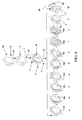
- Figure 1 shows the progressive building up of a model through processes depicted at A through J.
- the actual shape of the model depicted in the figures is purely for illustrative purposes only, and is to be understood as not limiting, in any manner.
- the creation of the first feature of the model known as the base feature 0 is depicted.
- B depicts the creation of another feature, a datum plane that will be referred to as the base-level datum plane 1.
- This is a reference feature as described above and acts as a first coordinate reference.
- the arrows 13 that flow from the creation of one feature to another indicate a parent/child relationship between the originating feature created and the feature(s) to which the arrow points.
- the base feature 0 is the parent of the base-level datum plane.
- any change to the parent will affect the child (e.g., rotate the parent 90 degrees and the child rotates with it), and deletion of the parent results in deletion of the child. This effect ripples all the way down the family line.
- the base-level datum plane 1 is the child of the base feature 0
- any change to the base-level datum plane will have no effect upon the base feature, but will affect all its progeny.
- the base-level datum plane is useful as a positional tool.
- the positioning of the base-level datum plane 1 with respect to the base feature 0 be chosen so as to make the most use of the base-level datum plane as a positional tool.
- the base-level datum plane 1 is chosen to coincide with the center of the cylindrical base feature. By rotating the base-level datum plane symmetrically with the center of the base feature, all progeny will rotate symmetrically about the base feature as well.
- Differently shaped base features may suggest differently positioned base-level datum planes.
- datum planes are used here because that is the coordinate system utilized by Unigraphics® software and is therefore illustrative only. Other software or systems may use coordinate reference features that are linear or three-dimensional. It is noteworthy then to appreciate that the teachings disclosed herein are not limited to planar reference features alone and may include various other reference features.
- a second coordinate reference may be created as a child of the first coordinate reference described above, though this is not strictly necessary.
- three datum planes 2, 3, and 4 are created. Each datum plane is oriented orthogonal to the others so that the entire unit comprises a three-dimensional coordinate system 6.
- the 3-D coordinate system 6 thus created is a relative one, meaning it rotates and moves along with the model. This is in contrast to an absolute coordinate system that exists apart from the model and as is common to all CAD/CAM software. Unigraphics® software for example, actually includes two absolute coordinate systems, a "world" coordinate system and a more local "working level" coordinate system.
- FIG. 1 and 2 there are numerous ways and configurations possible to establish the 3-D coordinate system 6.
- three independent datum planes each referenced to another reference, or three datum planes relative to one another, where a first datum plane 2 may be referenced to a particular reference.
- a preferred method is to create a first datum plane 2 that is the child of the base-level datum plane 1 and offset 90 degrees therefrom.
- a second datum plane 3 is created as a child of the first datum plane 2 and is offset 90 degrees therefrom. Note that the second datum plane 3 now coincides with the base-level datum plane 1, but they are not the same plane.
- any movement of the base-level datum plane 1 will result in corresponding movement of first 2 and second 3 datum planes of the 3-D coordinate system 6.
- the third datum plane 4 of the 3-D coordinate system 6 is created orthogonal to both the first and second planes, but is a child of the base feature 0 and will preferably coincide with a surface of the base feature. This is preferred with software that requires that physical features be mounted, or "placed", on a surface though they may be positioned relative to any number of datum planes. While not required, or explicitly enumerated, the third datum plane 4 may further include associative relationships with the first datum plane 2 and second datum plane 3, or any other reference plane.
- the third datum plane of the 3-D coordinate system is therefore referred to as the "face plane,” while the first two datum planes of the 3-D coordinate system are referred to as the "positional planes". All physical features added to the model from hereon will be “placed” onto the face plane and positioned relative to the positional planes datum planes 2 and 3 respectively of the 3-D coordinate system. It will be understood that the abovementioned example of feature placement is illustrative only, and should not be construed as limiting. Any datum plane may operate as a "face plane” for feature placement purposes. Moreover, any feature may also be oriented relative to a reference axis, which may be relative to any reference, which may include, but not be limited to, a datum plane, reference plane, reference system, and the like, as well as combinations of the foregoing.
- the system now includes the datum planes 2, 3, and 4, which may be manipulated by the single base-level datum plane 1 so as to affect the positioning of all features added to the base feature 0, but with the constraint that the "placement" of each feature is fixed relative to a face of the base feature 0.
- This is but one of many possible arrangements but is preferred in the Unigraphics® environment for its flexibility. Movement of the base-level datum plane 1 results in movement of the first two positional 2, 3 planes, but need not necessarily affect the datum plane 4. The result is that objects will move when the base-level datum plane 1 is moved, but be constrained to remain placed in the face plane. It is found that this characteristic allows for more convenient and detailed adjustment, though it is a preferred, rather than a mandatory characteristic of the invention.
- each feature is therefore a grandchild, great-grandchild, and great-great-grandchild of the base feature 0 by virtue of being a child of the face datum plane 4, first datum plane 2 and second datum plane 3, respectively.
- each feature added to the coordinate system of the model is independent of the others. That is to say, in the example depicted in FIG. 1 that no physical feature (except the base feature) is the parent of another. Since no physical feature is a parent, it follows that each individual physical feature may be added, edited, suppressed, or even deleted at leisure without disturbing the rest of the model.
- This characteristic of the disclosed embodiment that permits model development to proceed approximately at an order of magnitude faster than traditional "vertical" CAD/CAM development.
- the example provided identifies features exhibiting no respective associative relationships, such a characteristic is not necessary. Features may exhibit associative relationships with other features as well as other elements of the model. The constraint this adds is the loss of independence (and hence modeling simplicity) among the several features.
- certain form features may be preferably dependent from other form features or model elements rather than directly dependent as children from the 3-D coordinate system as described herein.
- an edge blend may preferably be mounted on another physical feature, not a datum plane.
- Such features will preferably be added to a single physical feature that itself is a child of the 3-D coordinate system, the intent being to keep the lineage as short as possible to avoid the rippling effect of a change whenever a feature is altered or deleted.
- additional datum planes may be added as features to the 3-D coordinate system as children just like any physical feature. These would be added as needed to position other physical features, or to place them on surfaces in addition to the datum plane 4. Any additional face planes needed to mount features should be at the same level as the 3-D coordinate system, that is to say a sibling of the original datum plane 4, not a child of it. In the example shown, such an added plane would be created as a child of the base feature 0 just as the third datum plane 4 is.
- FIG. 4 also depicts the progressive building up of a model via process depicted at A' through J'.
- the actual shape of the model depicted in the figures is once again, purely for illustrative purposes, and is to be understood as not limiting, in any manner.
- a set of coordinate references is established.
- three datum planes are created. Similar to the abovementioned horizontally structured modeling disclosure, each datum plane may be oriented orthogonal to the others so that the entire unit comprises a three-dimensional coordinate system 6.
- each datum plane or 3-D coordinate system may be positioned and oriented relative to some other reference, for example an absolute reference or coordinate system.
- the 3-D coordinate system 6 may be relative to another reference, or an absolute reference such as the reference supplied by the Unigraphics® environment. This means it may rotate and move along with a reference.
- a preferred method when utilizing Unigraphics® software is to create a first datum plane 2. Then, a second datum plane 3 is created independent of the first datum plane 2 and may, but need not be, offset 90 degrees therefrom. The third datum plane 4 is created, and once again, may be orthogonal to both the first datum plane 2 and second datum plane 3, but not necessarily so, thereby formulating the orthogonal 3-D coordinate system 6.
- datum planes features may be placed upon them just as they may be placed upon any physical feature, making the 3-D coordinate systems created from them much more convenient than simple coordinate systems found on other CAD/CAM software. It should be noted, however, that these techniques apply to software that utilize datum planes such as Unigraphics®. For other software, there may and likely will be other techniques to establishing a 3-D coordinate system relative to the model to which the physical features of the model may be positioned and oriented. Once, again, this method is not to be construed as limited to the use of datum planes or to the use of Unigraphics® software.
- reference datum planes e.g., 2, 3, and 4 may, but need not be, associative.
- the relationship between the datum planes may be as simple as position and orientation.
- a base feature 0 is added as a first feature, assembly or a sketch to an existing coordinate system or associative datum plane structure comprising datum planes 2, 3, and 4.
- the elimination of an associative relationship among the datum planes 2, 3, and 4, the 3-D coordinate system 6, and the base feature 0 provides significant latitude in the flexibility attributed to the 3-D coordinate system 6 and the base feature 0. Therefore, the datum plane structure comprising 2, 3, and 4 may take its place as the zero'th level feature of the model.
- the base feature 0 is added at B' and the physical features, or form features 5a-5g are added at D' through J' in a manner similar to that described earlier.
- a parent child relationship is eliminated between the base feature 0 and the physical features, or form features 5a-5g.
- an associative relationship in this case a parent child relationship is created between the physical features, or form features 5a-5g and the datum planes 2, 3, and 4.
- the base-level datum plane was chosen to coincide with the center of the cylindrical base feature. By rotating the base-level datum plane symmetrically with the center of the base feature, all progeny will rotate symmetrically about the base feature as well. Differently shaped base features will suggest differently positioned base-level datum planes. In this embodiment, the physical features, or form features 5a-5g and the datum planes 2, 3, and 4 maintain an associative relationship, but neither with the base feature 0.
- the 3-D coordinate system When the 3-D coordinate system is established before the fundamental shape is placed on the screen and presented to the user, it simplifies substitution of the base feature 0 to other models. For example, where it may be desirable to change one base feature 0 for another, and yet preserve the later added physical features, or form features e.g., 5a-5g.
- the disclosed embodiment simplifies this process by eliminating the parent child relationship between the base feature 0 and the datum planes. Therefore the base feature 0 may be removed and substituted with ease.
- the physical features, or form features 5a-5g and the datum planes 2, 3, and 4 may easily be adapted to other base features of other models.
- the manufacturing process of a disclosed embodiment utilizes the horizontal CAD/CAM methods described above to ultimately generate process instructions and documentation used to control automated machinery to create a real-world part based on a horizontally-structured model.
- extracts are used to generate process sheets or other instructions for each requirement for machining of the real-world part.
- a suitable blank may be selected or created, usually a cast piece, the dimensions and measurements of which are used as the virtual blank 10 for the virtual machining of the 3-D parametric solid model with the horizontally structured manufacturing method.
- a virtual blank 10 may be selected, and a blank manufactured to match.
- a suitable blank or component is selected, a virtual blank 10 is generated therefrom, commonly a referenced set of geometries from a model termed a reference set 26 (e.g., a built up product model of a part). From this referenced set of geometries a three-dimensional (3-D) parametric solid model termed a virtual blank 10 may be generated or created for example via the Wave link or Promotion process of Unigraphics®, which includes all of the modeled details of the completed part.
- a horizontally-structured 3-D parametric solid model is created in a manner that describes machining operations to be performed on the blank so as to produce the final real-world part.
- This horizontally structured model will be referred to as the master process model 20.
- the master process model 20 depicted includes with it, but is not limited to, the virtual blank 10, added manufacturing features 12a-12j by way of virtual machining, and datum planes 2, 3, and 4 all in their respective associative relationships as exhibited from the geometries and characteristics of the reference set 26.
- FIG. 6 depicts the virtual machining process of the exemplary embodiment where manufacturing features are "machined" into the virtual blank 10. For example, at N, O, and P various holes are “drilled” into the virtual blank 10 as manufacturing features 12a, 12b, and 12c respectively. Moreover, at S a large hole is created via a boring operation at 12f. It is also noted once again, just as in the horizontally structured modeling methods discussed above, that the datum planes 2, 3, and 4 may be added as features to the 3-D coordinate system as children just like any form feature (e.g., 5a-5g) or manufacturing feature 12a-12j. These may be added as needed to position other features, or to place them on surfaces in addition to the datum planes 2, 3, and 4. For example as shown in FIG.
- such an added plane may be created as a child of the virtual blank 10 just as the third datum plane 4 is.
- the model has been flipped around and a face plane 7 is placed on the back as a child of the virtual blank 10. This allows manufacturing features 12i and 12j to be placed on the back of the object, in this case "counter-bores” for the holes "drilled" through the front earlier.
- process model 20 may be the completed horizontally structured model depicted at W in FIG. 6 including all of the "machining" operations.
- some CAD/CAM software packages may require that the addition of the features be in a particular order, for example, in the same order as manufacture.
- a method for reordering the features is beneficial.
- the reordering method is a displayed list of features 24 that the user may manipulate, the order of features in the list corresponding to that in the master process model 20.
- Process instructions and documentation termed process sheets 23 are then generated from each operation.
- the process sheets 23 are used to depict real-time in-process geometry representing a part being machined and can be read by machine operators to instruct them to precisely machine the part.
- FIG. 7 An example of a Unigraphics® process sheet 23 is shown in FIG. 7.
- the geometry can then be used to direct downstream applications, such as cutter paths for Computer Numerical Code (CNC) machines.
- CNC Computer Numerical Code
- the software is adapted to generate such CNC code directly and thereby control the machining process with minimal human intervention, or even without human intervention at all.
- CNC code is generated by the Manufacturing software module, which is configured to automate the machining process.
- the traditional approach to manufacturing modeling is to create individual models representing the real-world component at particular operations in the manufacturing process. If a change or deletion is made in one model, it is necessary to individually update each of the other models having the same part.
- Using the horizontally structured modeling disclosed herein it is now possible to generate a horizontally structured master process model 20 and generate a set of process sheets 23 that are linked thereto. Any changes to the master process model 20 are reflected in all the process sheets 23.
- this linkage between the master process model 20 and the process sheets 23 is preferably achieved through the use of extracted in-process models, called virtual extract(s) or extracted bodies, hereinafter denoted extract(s) 22, that are time stamped and linked to the master process model 20.
- Each extract 22 represents part of the manufacturing process and each is a child of the master process model 20. Any changes to the master process model 20 are automatically reflected in all the relevant extract(s) 22, but changes to the extract(s) 22 have no effect on the master process model 20.
- Each extract 22 is a three-dimensional snapshot of the master process model 20 at a moment in "time" of its creation. The extracts 22 created for each operation are children of the master process model 20. By changing the master process model 20, the extracts 22, and therefore, the manufacturing process is automatically updated.
- the order of creation of the extracts 22 is preferably dictated by a user-friendly graphical interface 21, hereinafter referred to as a model navigation tool 21.
- the model navigation tool 21 will preferably allow the user to arrange the order of features through simple mouse operations so as to make manipulation of the master process model 20 as simple and intuitive as practicable.
- a model navigation tool provides similar functionality and capability.
- a process sheet 23 is generated for each extract 22 in one-to-one correspondence.
- the master process model 20 is preferably created using the horizontally-structured methods described above, editing the master process model 20 is a simple and expedited matter of adding, editing, suppressing, or deleting individual features of the master process model 20, which through the extract(s) 22 will automatically update all the process sheet(s) 23.
- the disclosed method of generating process sheets has resulted in a 50% reduction in the time needed to create new process sheets and an 80% reduction in the time required to revise existing process sheets over the "vertical" modeling methods.
- this principle may be extended downstream in the manufacturing process model by utilizing the electronic data for CNC programs, tooling (i.e., cutting tool selection), and fixture design by direct transmission to the machining tools without the need for process sheets 23 and human intervention.
- tooling i.e., cutting tool selection
- fixture design by direct transmission to the machining tools without the need for process sheets 23 and human intervention.
- this may be achieved by creating a reference set to the particular extract 22 and including it in to a new file via virtual assembly, similar to the method employed for the creation of the virtual blank 10 discussed earlier.
- the extract 22 therefore, is used to create the corresponding geometry.
- Software must then be provided to adapt the CAD/CAM software to translate the geometry into CNC form.
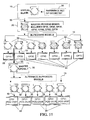
- the method leading to generating process sheets 23 initiates with selection of a virtual blank 10 and then proceeding to add via virtual machining, manufacturing features (12a-12j) to the virtual blank 10 in a horizontally-structured manner as described earlier. Following each virtual machining operation, an extract 22 is made representing the state of the master process model 20 at that instant of the manufacturing process.
- the order in which the features are machined onto the real-world part is decided either through automated means or manually by the user with the model navigation tool 21.
- an "extract” is then preferably made of the master process model 20 corresponding to each added feature representing a manufacturing position or operation.
- the "extraction” is accomplished through a software module provided with the CAD/CAM software, otherwise the user may create a software program for the process.
- a Modeling Module includes software configured to handle the extraction process.
- the process sheets 23 may then be created from the extracts 22 that are added into the Drafting Module of the Unigraphics® software.
- an extract 22 is a three-dimensional "snapshot" of the assembly of the master process model 20 in progress, showing all of the manufacturing features 12a-12j up to that operation in the assembly, but none that come after it.
- the process sheet 23 derived from the extract 22 contains the instructions to machine the latest feature that appears at that "snapshot" in time.
- an extract 22 is an associative replica of master process model 20 depicting only those features, which have been added to that point in the manufacturing process. It is noteworthy to appreciate that; manufacturing features 12a-12j may thereafter be added to the extract 22 without appearing in the master process model 20, however any manufacturing features 12a-12j added to the master process model 20 will appear in the extract 22 if the particular manufacturing feature (e.g. one of 12a-12j) is directed to be added at or before the manufacturing procedure represented by the extract 22.
- the particular manufacturing feature e.g. one of 12a-12j
- a process sheet 23 is a document defining the sequence of operations, process dimensions, and listing of equipment, tools, and gauges required to perform an operation. Manufacturing personnel utilize process sheets to obtain the detailed information required to manufacture and inspect the components depicted thereon.
- Each process sheet 23 includes, but is not limited to, both graphics and text.
- the graphics may include the dimensional characteristics of the part for the particular portion of the manufacturing process, the text contains various data identifying the part and operation and noting revisions. In the example shown in FIG.
- a first alternative embodiment of the manufacturing process which utilizes the horizontal CAD/CAM modeling methods described above to ultimately generate process instructions and documentation used to control automated machinery to create a real-world part based on a horizontally-structured model.
- process model "extracts" are used to generate process sheets or other instructions for each procedure to machine the real-world part.
- a suitable blank may be selected or created, for example, a cast piece, the dimensions and measurements of which, are used as the virtual blank 10 for the virtual machining of the 3-D parametric solid model with the horizontally structured manufacturing method.
- a virtual blank 10 may be selected, and a blank could be manufactured to match it. This alternative may prove be less desirable as it would incorporate additional machining which would not be necessary if the virtual blank 10 initiates with the blank's dimensions. It is nonetheless stated to note that the method disclosed includes, and is not limited to a variety of approaches for establishing the blank and a representative virtual blank 10 for the model.
- a suitable blank or component is selected.
- a virtual blank 10 is generated therefrom, commonly a referenced set of geometries from a model termed a reference set 26 shown in FIG 9 (e.g., a built up product model of a part). From this referenced set of geometries a three-dimensional virtual blank 10 model may be generated or created for example via the Wave link or Promotion process of Unigraphics®, which includes all of the modeled details of the completed part.
- a horizontally-structured 3-D parametric solid model is generated or created in a manner that describes machining operations to be performed on the blank so as to produce the final real-world part.
- This horizontally structured model will be referred to as the master process model 20.
- the master process model 20 depicted includes with it, but is not limited to, the virtual blank 10, added manufacturing features 12a-12j by way of virtual machining, and datum planes 2, 3, and 4 all in their respective associative relationships as exhibited from the geometries and characteristics of the reference set 26.
- the master process model 20 logically, is a child of the reference set 26 and virtual blank 10, thereby ensuring that if a design change is implemented in the product model utilized for the reference set 26, such a change flows through to the master process model 20 and manufacturing process.
- Unique to this embodiment is the lack of a mandatory associative relationship among the master process model 20 and the datum planes 2, 3, and 4 which comprise the reference 3-D coordinate system 6 with respect to which, the form features and manufacturing features are positioned and oriented.
- the virtual machining process of the exemplary embodiment where manufacturing features are "machined” into the virtual blank 10 is depicted.
- various holes are “drilled” into the virtual blank 10 as manufacturing features 12a, 12b, and 12c respectively.
- a large hole is created via boring operation at 12f.
- the datum planes 2, 3, and 4 may be added as features to the 3-D coordinate system as children just like any form feature (e.g., 5a-5g) or manufacturing feature 12a-12j. These may be added as needed to position other features, or to place them on surfaces in addition to the datum planes 2, 3, and 4. For example as shown in FIG.
- such an added plane may be created as a child of the virtual blank 10 just as the third datum plane 4 is.
- the model has been flipped around and a face plane 7 is placed on the back as a child of the virtual blank 10. This allows manufacturing features 12i and 12j to be placed on the back of the object, in this case "counter-bores” for the holes "drilled" through the front earlier.
- the master process model 20 may be recognized as the completed horizontally structured model depicted at W in FIG. 6 including all of the "machining" operations.
- some CAD/CAM software packages may require that the addition of the manufacturing features 12a-12j to be in a particular order, for example, in the same order as manufacture.
- a method for reordering the features may prove beneficial.
- the reordering method is a displayed list of features 24 that the user may manipulate, the order of features in the list corresponding to that in the master process model 20.
- process instructions and documentation termed process sheets 23 are then generated from each operation.
- the process sheets 23 are used to depict real-time in-process geometry representing a part being machined and can be read by machine operators to instruct them to precisely machine the part.
- FIG. 7 An example of a Unigraphics® process sheet 23 is shown in FIG. 7.
- the geometry can then be used to direct downstream applications, such as cutter paths for Computer Numerical Code (CNC) machines.
- CNC Computer Numerical Code
- the software is adapted to generate such CNC code directly and thereby control the machining process with minimal human intervention, or even without human intervention at all.
- each extract 22 is also a three dimensional solid model and represents the part under fabrication at a particular operation or time in the manufacturing process.
- Each extract 22 is a child of the master process model 20. Any changes to the master process model 20 are automatically reflected in all the relevant extract(s) 22, but changes to the extract(s) 22 have no effect on the master process model 20.
- each extract 22 need not necessarily exhibit an associative relationship with the datum planes 2, 3, and 4 respectively nor the manufacturing features 12a-12j respectively.
- An advantage of the disclosed embodiment then is, in the realization that any changes to the datum planes 2, 3, and 4 as well as the manufacturing features 12a-12j are independent of the relevant extract(s) 22 and vice versa.
- An additional characteristic of the exemplary embodiment is that each of the manufacturing features 12a-12j, now maintain associative relationships, in this case, parent/child relationships with the corresponding datum planes 2, 3, and 4. Therefore, changes to the datum planes are automatically reflected in all the relevant manufacturing features 12a-12j, but changes to the manufacturing features 12a-12j have no effect on the various datum planes.
- the manufacturing features 12a-12j may, but need not necessarily, exhibit an associative relationship among themselves.
- This separation of the associative relationships of master process model 20 and extracts 22 from datum planes 2, 3, and 4 and manufacturing features 12a-12j is one characteristic, which enables a user now to effectively manipulate the various elements of the manufacturing process models to facilitate easy substitutions into or out of a model.
- each extract 22 is a three-dimensional "snapshot" of the master process model 20 at a moment in "time” of its creation in the manufacturing process.
- the extracts 22 created for each operation are children of the master process model 20.
- the order of creation of the extracts 22 is preferably dictated by a user-friendly graphical interface 21, hereinafter referred to as a model navigation tool 21.
- the model navigation tool 21 will preferably allow the user to arrange the order of features through simple mouse operations so as to make manipulation of the master process model 20 as simple and intuitive as practicable.
- a model navigation tool provides similar functionality and capability.
- a process sheet 23 is generated for each extract 22. In the example depicted in FIG. 8, a process sheet 23 is generated for each extract in one-to-one correspondence.
- the master process model 20 is preferably created using the horizontally-structured methods described above, editing the master process model 20 is a simple and expedited matter of adding, editing, suppressing, or deleting individual features of the master process model 20, which, through the extract(s) 22, will automatically update all the process sheet(s) 23.
- this principle may be extended further downstream in the manufacturing process model by utilizing the electronic data for CNC programs, tooling (i.e., cutting tool selection), and fixture design by direct transmission to the machining tools without the need for process sheets 23 and human intervention.
- tooling i.e., cutting tool selection
- fixture design by direct transmission to the machining tools without the need for process sheets 23 and human intervention.
- such automation may be achieved by creating a reference set (analogous to the reference set 26) to the particular extract 22 and including it in a new file via virtual assembly, similar to the method employed for the creation of the virtual blank 10 discussed earlier.
- the extract 22 therefore, is used to create the corresponding geometry.
- Software must then be provided to adapt the CAD/CAM software to translate the geometry into CNC form.
- the method of generating process sheets 23 initiates with selection a virtual blank 10 and then proceeding to add manufacturing features 12a-12j (FIG.6) to the virtual blank 10 in a horizontally-structured manner as described earlier.
- an extract 22 is made representing the state of the master process model 20 at that instant of the manufacturing process.
- the order in which the features are to be machined into the real-world part is decided upon either through automated means or manually by the user with the model navigation tool 21.
- an "extract” is then preferably made of the master process model 20 corresponding to each added feature representing a manufacturing position or operation.
- the "extraction” is accomplished through a software module provided with the CAD/CAM software, otherwise the user may develop software to program the process.
- the Modeling Module includes software to handle the extraction process.
- the process sheets 23 may then be created from the extracts 22 that are added into the Drafting Module of the Unigraphics® software.
- an extract 22 is a "snapshot" of the assembly of the master process model 20 in progress, showing all of the manufacturing features (e.g. one or more of 12a-12j (FIG. 6)) up to that point in the assembly, but none that come after it.
- the process sheet 23 derived from the extract 22 contains the instructions to machine the latest feature that appears at that "snapshot" in time.
- an extract 22 is an associative replica of master process model 20 depicting only those features, which have been added to that point in the manufacturing process.
- manufacturing features 12a-12j may be added to the extract 22 without appearing in the master process model 20, however any features added to the master process model 20 will appear in the extract 22 if the feature is directed to be added at or before the manufacturing procedure represented by the extract 22.
- a process sheet 23 is a document defining the sequence of operations, process dimensions, and listing of equipment, tools, and gauges required to perform an operation. Manufacturing personnel utilize process sheets to obtain the detailed information required to manufacture and inspect the components depicted thereon.
- Each process sheet 23 includes, but is not limited to, both graphics and text.
- the graphics may include, but not be limited to, the dimensional characteristics of the part for the particular portion of the manufacturing process
- the text may include, but not be limited to various data identifying the part and operation and noting revisions, and corresponding tooling fixtures and gauges, and the like.
- the horizontally structured modeling and manufacturing process modeling utilizes the horizontal CAD/CAM modeling methods described above.
- the first embodiment is further enhanced to ultimately generate CAD/CAM models and process sheets that are used to control automated machinery to create a real-world part based on a horizontally structured CAD/CAM models.
- horizontally structured modeling methods and horizontally structured manufacturing process modeling methods as disclosed above are employed to facilitate the generation of one or more manufacturing process models for creating the actual part.
- This manufacturing process model is termed a master process model. "Extracts" of master process models are utilized to generate process sheets or other instructions for each procedure to machine a real-world part.
- a link and unlink functionality provides for automatic references and the modification of links associative relationships among one or more CAD/CAM models and model elements.
- the link/unlink function allows a newly created or existing model or model element to be replaced by another.
- the features associated with a first model may be reassociated to another model with little if any impact to the associated features.
- the exemplary embodiment takes advantage of the existing link and unlink functionality of the Unigraphics® ⁇ CAD/CAM system software.
- an illustration employing Unigraphics® software is employed.
- the disclosed method includes the removal of feature dependency between modeling elements, in this instance a master process model generated as disclosed earlier, and a linked geometry. Therefore, enabling the linked geometry to be replaced by a new geometry without losing the prior positional and orientational dependencies associated with the linked geometry. Therefore, this capability maintains the associative relationships generated between a linked geometry and a master process model.
- a suitable blank may be selected or created, a cast piece for instance, the dimensions and measurements of which, are used as the virtual blank 10 for the virtual machining of the 3-D parametric solid model with the horizontally structured manufacturing method.
- a virtual blank 10 may be selected, and a blank could be manufactured to match it.
- a suitable blank or component is selected.
- a virtual blank 10 may be generated therefrom, commonly a referenced set of geometries from a model termed a reference set 26 (e.g., a built up product model of a part). From this referenced set of geometries a three-dimensional virtual blank 10 model may be generated or created via the Wave link or Promotion process of Unigraphics®, which includes all of the modeled details of the completed part.
- a horizontally-structured 3-D parametric solid model is generated or created in a manner that describes machining operations to be performed on the blank so as to produce the final real-world part.
- This horizontally structured model is again referred to as the master process model 20.
- the master process model 20 depicted includes with it, but is not limited to, the virtual blank 10, added manufacturing features 12a-12j (FIG. 6) by way of virtual machining, and datum planes 2, 3, and 4 all in their respective associative relationships as exhibited from the geometries and characteristics of the reference set 26.
- the master process model 20 is a 3-D parametric solid model representative of the geometry of a reference set 26, which includes the reference set 26 associative relationships. Moreover, the master process model 20 may be manipulated and modified as required to model the process of fabricating the actual part. Once again, this master process model 20, logically, is a child of the reference set 26. Moreover, once again, no mandatory associative relationship need exist among the master process model 20 (e.g., in a Unigraphics® environment, the Wave linked geometry) and the datum planes 2, 3, and 4 which comprise the reference 3-D coordinate system 6 with respect to which, the features are positioned and oriented or among the datum planes 2, 3, and 4.
- interchangeable master process models 20 may be generated without impacting the particular features or datum planes (e.g., 2, 3, and 4) utilized. For example, different reference sets or geometries may be selected and a new master process model generated therefrom and subsequently, the same features and associated datums added.
- FIG. 6 the virtual machining process of the exemplary embodiment where manufacturing features are "machined" into the virtual blank 10 is depicted. The process is similar to that disclosed above and therefore, need not be repeated.
- the master process model 20 may recognize the master process model 20 as the completed horizontally structured model depicted at W in FIG. 6 including all of the "machining" operations.
- some CAD/CAM software packages may require that the addition of the manufacturing feature(s) 12a-12j to be in a particular order, for example, in the same order as manufacture.
- a method for reordering the features may prove beneficial.
- link/unlink capability realizes its potential and significance primarily due to the characteristics of the horizontally structured model and manufacturing processes disclosed herein. Specifically, the separation/distribution of associative relationships in the models provides the enhancement achieved.
- each extract 22 is also a three dimensional solid model and represents the part under fabrication at a particular operation or time in the manufacturing process and includes the properties as described in earlier embodiments.
- a process sheet 23 is generated for each extract 22 in one-to-one correspondence as described earlier. Since the master process model 20 is preferably created using the horizontally-structured methods described above, editing the master process model 20 is a simple and expedited matter of adding, editing, suppressing, or deleting individual features of the master process model 20, which through the extract(s) 22, will automatically update all the process sheet(s) 23.
- this principle may be extended further downstream in the manufacturing process model by utilizing the electronic data for CNC programs, tooling (i.e., cutting tool selection), and fixture design by direct transmission to the machining tools without the need for process sheets 23 and human intervention.
- model link/unlink functionality coupled with the horizontally structured process modeling as disclosed earlier brings forth new opportunities for enhancement of CAD/CAM modeling manufacturing processes.
- One such opportunity is horizontally structured CAD/CAM modeling and manufacturing process modeling methods to facilitate alternate operations and manufacturing processes.
- horizontally structured CAD/CAM modeling and manufacturing process modeling methods to facilitate alternate operations and manufacturing processes.
- the link/unlink and extraction function disclosed above is employed to facilitate performing an alternative manufacturing process.
- the alternative manufacturing process may be initiated via the "extraction" process of an existing model generating an alternate master process model e.g., a replica of a first or existing model.
- the existing model may include, but not be limited to, a reference set, a newly created master process model, or an existing master process model.
- an illustration employing Unigraphics® software is disclosed.
- the disclosed method includes the creation of a master process model 20, and performing virtual machining thereon, followed by the generation of extracts 22 and process sheets in a manners as disclosed above. Additionally, an alternate master process model 30 is generated and likewise, followed by the generation of alternate extract(s) 32 and ultimately alternate process sheet(s) 33 therefrom. Thereby, multiple alternate processes for manufacturing operations may be created.
- a master process model 20 is created and includes the characteristics, relationships and limitations as described above. To avoid duplication, reference may be made to the abovementioned embodiments for insight concerning the generation or creation of a master process model and any characteristics thereof.
- one or more extract(s) may be generated from the master process model 20. From the extract(s) 22, corresponding process sheets may also be generated.
- the alternate master process model 30 is created following the completion of the "virtual" machining of the desired common manufacturing features (e.g. 12a, and 12b for instance).
- the alternate master process model 30 may be extracted once again from the last in-process process model 22 including the particular manufacturing features desired to generate a new 3-D parametric solid model to facilitate the definition of an alternate process of manufacturing.
- extracts may be made during the virtual machining process and therefrom process sheets generated.
- alternate extracts 32 of the alternate master process model 30 are created at various operations of the manufacturing process, in this case the alternate manufacturing process.
- alternate process sheets 33 may be generated for specifying the manufacturing operations.
- model link/unlink functionality coupled with the horizontally structured process modeling as disclosed earlier brings forth new opportunities for enhancement of CAD/CAM modeling and manufacturing process modeling.
- One such opportunity is horizontally structured CAD/CAM modeling and manufacturing process modeling methods to facilitate large-scale manufacturing processes incorporating a large (e.g. more than 50 operations) number of manufacturing operations.
- horizontally structured CAD/CAM modeling and manufacturing process modeling methods to facilitate large-scale manufacturing processes incorporating a large (e.g. more than 50 operations) number of manufacturing operations.
- horizontally structured modeling methods and the part link/unlink embodiments as disclosed above are employed to facilitate the generation of a manufacturing process for creating an actual part (e.g., a method for modeling and performing a large number of manufacturing operations).
- the manufacturing process comprises a plurality of models each termed master process models analogous to those described above.
- each of the master process models are generated and configured in a hierarchy and include associative relationships (e.g. links) configured such that changes in a "senior" master process model are reflected in all the subsequent or "junior” linked master process models.
- changes in the subsequent or "junior" master process models will not affect the more "senior” master process models.
- Extracts of each master process model are utilized to generate process sheets or other instructions for each procedure to machine a real world part just as described in earlier embodiments. Thereby, the combination of the multiple processes enabling large-scale manufacturing operations may be created.
- FIG. 12 to facilitate the method disclosed and large-scale model creation, once again, the link/unlink and extraction functions disclosed above are once again employed.
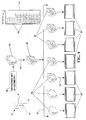
- To execute generating a large-scale manufacturing process multiple master process models e.g., 20a, 20b, and 20c are created each including a subset of the manufacturing operations required to complete the total manufacturing requirements. In the figure, by way of illustration of an exemplary embodiment, three such master process models 20a, 20b, and 20c are depicted.
- Each master process model 20a, 20b, and 20c is created in a separate file, the files linked in associative relationships as depicted by the arrows in the figure.
- the master process model 20a, 20b, and 20c may be created or generated in a variety of manners as described above.
- the master process model 20 may be generated via virtual machining of a virtual blank 10, which was an "extraction" from a reference set 26, as a replica of an existing model.
- a master process model is created and includes the characteristics, relationships and limitations as described in the abovementioned embodiments. To avoid duplication, reference may be made to the abovementioned embodiments for insight concerning a master process model and horizontally structured models.
- each of the master process models 20a, 20b, and 20c are configured in a hierarchy, in three separate files and include associative relationships (e.g. links) configured such that changes in a "senior" (e.g., 20a, 20b, and 20c respectively) master process model are reflected in all the subsequent linked master process models (e.g., 20b and 20c). However, changes in the subsequent master process models (e.g., 20c, and 20b, respectively) will not affect the prior master process models. Moreover the master process models are created, configured and linked with associative relationships such that changes to the reference set 26 or virtual blank 10 from which they originated, flow down to all master process models 20a, 20b, and 20c respectively.
- associative relationships e.g. links
- An exemplary embodiment further illustrates application to a large scale manufacturing process.
- a "senior" master process model, e.g., 20a is generated as disclosed herein, namely initiated with a virtual blank 10 as a replica of the desired reference set 26, virtual blank 10, or a product casting.
- the virtual machining necessary to add a first subset of all the desired manufacturing features for example, 12a, and 12b is performed.
- a second or junior master process model e.g., 20b in a separate file is generated from the first e.g. 20a.
- the subsequent desired manufacturing features to be associated with the second master process model e.g., 12c, and 12d are added to the second master process model e.g., 20b.
- a third master process model e.g., 20c is generated from the second e.g., 20b in yet another separate file and further subsequent manufacturing features e.g., 12e and 12f are added.
- Subsequent "junior" master process models may be generated in subsequent separate files as needed to accomplish the entire large scale manufacturing process and yet keep the individual file size manageable.
- a particular feature of the exemplary embodiment is that it would allow the user to readily add new manufacturing features any where in the large scale manufacturing process model without disrupting the every file and model.
- global changes which affect the entire model may be made at the highest level via the first master process model e.g., 20a, reference set 26 geometry, or virtual blank 10 which then flow down to all the subsequent models by virtue of the associative relationships among them.
- the virtual blank 10 and the multiple master process model(s) 20a, 20b, and 20c with their respective associated relationships and progeny are applied to facilitate a large-scale manufacturing process.
- one or more in process models or extract(s) may be generated from each of the master process model(s) 20a, 20b, and 20c respectively (in this instance three are depicted).
- the extracts 22 correspond to the state of the respective master process models 20a, 20b, and 20c at various operations for the virtual machining of the manufacturing features (e.g., 12a-12j of FIG. 6). Referring also to FIGs.
- corresponding process sheets may also be generated.
- extracts, of the respective master process models 20a, 20b, and 20c are created at various operations of the manufacturing processes associated with a particular master process model of the plurality.
- corresponding process sheets 23 may be generated for specifying the manufacturing operations.
- the extracts 22 and process sheets 23 are created and include the characteristics, relationships and limitations as described above for horizontally structured models and horizontally structured process models. To avoid duplication, reference may be made to the abovementioned embodiments for insight concerning in process models or extracts and process sheets.
- the large-scale manufacturing operations process capability disclosed realizes its potential and significance primarily due to the characteristics of the horizontally structured model and manufacturing processes disclosed herein. Specifically, the separation/distribution of associative relationships in the models provides the enhancement achieved. In contrast, where the traditional approach to manufacturing modeling was to create separate individual models representing the real-world component at numerous particular operations in the manufacturing process. If a change or deletion was made in one model, it was necessary to individually update each of the other models having the same part.
- the horizontally structured modeling disclosed herein and employing the model link/unlink capabilities it is now possible to generate multiple horizontally structured master process model(s) linked in a manner such that changes in one model are automatically carried out in other linked models enabling a multitude of alternate manufacturing processes. Further, the subsequent process sheets 23 that are linked thereto are also automatically updated. Any changes to a particular master process model 20a, 20b, or 20c are automatically reflected in the corresponding extracts 22 and process sheets 23.
- the model link/unlink functionality coupled with the horizontally structured process modeling as disclosed earlier brings forth new opportunities for enhancement of CAD/CAM modeling and manufacturing process modeling.
- One such opportunity is horizontally structured CAD/CAM modeling and manufacturing process modeling methods to facilitate charted parts manufacturing.
- Charted parts include, but are not limited to a group of machined parts exhibiting one or more common manufacturing features. For example, two independent machined parts that originate from the same casting.
- manufacturing models may need to be created for each individual part to be fabricated.
- a separate model is created for each manufacturing operation of a charted part where some elements of the model are common and yet no associative relationship exists between the manufacturing process models, a problem arises when one part or model requires an addition or modification. That being, that all subsequent models will also require manual updates to incorporate the desired modification. For example if a global change to a common casting was required.
- Disclosed herein is an embodiment, which utilizes the features and characteristics of horizontally structured manufacturing process and the link/unlink functionality disclosed earlier to develop manufacturing process models that contain multiple parts that share common manufacturing features and element(s).
- all common manufacturing features may be linked in associative relationships, while uncommon manufacturing features need not be associatively linked.
- Such a configuration coupled with the characteristics of the associative relationships between subsequent models, processes, or operations dictates that a change made in one is reflected down the entire stream.
- horizontally structured modeling methods as disclosed above are employed to facilitate the generation of a manufacturing process for creating charted parts (e.g., a method for modeling and fabricating charted parts with some common and uncommon features).
- a manufacturing process for creating charted parts e.g., a method for modeling and fabricating charted parts with some common and uncommon features.
- link/unlink and extraction functions disclosed above are here again employed.
- the manufacturing process comprises a plurality of models each termed master process models analogous to those described above once again created or generated from a virtual blank 10 extracted from the geometry of a reference set 26 or a casting model.
- master process model 20 generated, which is virtual machined to include the manufacturing features common to all charted parts.
- master process model 20d is created or generated and each of the part specific manufacturing features are added.
- a single common master process model is depicted as well as a single master process model corresponding to a particular charted part.
- master process models are created and include the characteristics, relationships and limitations as described above for horizontally structured models. To avoid duplication, reference may be made to the abovementioned embodiments for insight concerning a master process model and horizontally structured models.
- each of the master process models 20 and 20d includes associative relationships (e.g. links) as depicted by the arrows in the figure, with the virtual blank 10 and subsequent corresponding in process models (extracts) 22.
- Each associative relationship is characterized such that changes in the reference set 26, virtual blank 10, or particular master process model 20 or subsequent master process model 20d are reflected in all the subsequent linked in process models (extracts) 22 corresponding to that particular master process model.
- the master process models 20 and 20d may be created in a variety of manners as described in the embodiments above.
- the master process model 20 may be created or generated via virtual machining of a virtual blank 10, which was created as a linked body or a promotion from a reference set 26, as a replica of an existing model.
- a master process model may also be generated by the extraction process from an existing model element
- each of the master process models 20 and 20d are configured to include associative relationships (e.g. links) configured such that changes in a reference set, 26 or virtual blank 10 are reflected in the subsequent linked master process models and their progeny.
- associative relationships e.g. links
- changes in the master process models e.g., 20 and 20d will not affect the parents.
- An exemplary embodiment further illustrates application to a charted parts manufacturing process.
- Two master process models, e.g., 20 and 20d are generated as disclosed herein, namely initiated with a virtual blank 10 as a replica of the desired reference set 26 or product casting.
- the virtual machining necessary to add all common desired manufacturing features, for example, 12a, 12b, and 12c (FIG. 6) (12a-12j are depicted in FIG. 13) is performed on one master process model 20 for example.
- a subsequent master process model e.g., 20d is generated.
- the manufacturing features from the master process model 20 are copied to the subsequent master process model 20d.
- the common manufacturing features for example, 12a, 12b, and 12c are applied in the subsequent master process model 20d with modifiable constraints.
- the modifiable constraints enable the user to individually select and dictate the linkages and relationships among the various model elements. In this instance, for example this may include, but not be limited to, the linkages between the common manufacturing features (e.g.12a, 12b, and 12c) and the first master process model 20. Therefore the subsequent master process model 20d may include the common manufacturing features (e.g.12a, 12b, and 12c) and yet not necessarily include associative relationships with the master process model 20.
- the subsequent desired manufacturing features e.g., 12d, and 12e may then be added to the subsequent master process model e.g., 20d.
- a plurality in process models or extract(s) may be generated from each of the master process model(s) 20, and 20d respectively (in this instance two are depicted). From the extract(s) 22 associated with each master process model e.g., 20 and 20d corresponding process sheets 23 may also be generated. Where again, extracts, of the respective master process models 20 and 20d are created at various operations of the manufacturing processes associated with a particular master process model of the plurality. Once again from these extracts 22, corresponding process sheets 23 may be generated for specifying the manufacturing operations.
- extracts 22 and process sheets 23 are created and includes the characteristics, relationships and limitations as described above for horizontally structured models and horizontally structured process models. To avoid duplication, reference may be made to the abovementioned embodiments for insight concerning in process models or extracts and process sheets.
- a particular feature of the exemplary embodiment is that it would allow the user to readily add new manufacturing features and thus new charted parts any where in the charted parts manufacturing process model without disrupting the every file and model.
- global changes, which affect the entire model may be made at the highest level via the master process model with the common features e.g., 20 or the referenced geometry, which then flow down to all the subsequent models by virtue of the associative relationships among them.
- Product and process modeling traditionally, involves the creation of two models, one to represent the finished component and another to represent the manufacturing processes.
- the two models generally include no feature linkages, particularly in the final product model and therefore, the models have to be manually updated to reflect any changes to the manufacturing process or the finished component. Moreover, certain operations may need to be repeated for both the product model and the manufacturing process modeling. Maintaining two models and manually updating models is cumbersome and expensive.
- the model link/unlink functionality coupled with the horizontally structured process modeling as disclosed earlier brings forth new opportunities for enhancement of CAD/CAM modeling and manufacturing process modeling.
- One such opportunity is horizontally structured CAD/CAM modeling and manufacturing process modeling methods to facilitate concurrent product and process design.
- An exemplary embodiment addresses the deficiencies of known manufacturing modeling methods by creating a single master model to represent the finished component or product and the manufacturing process for the product.
- the exemplary embodiment comprises a model termed master product and process concurrent model analogous to those described above, but including both the product design model and the manufacturing process model.
- the master product and process concurrent model includes associative relationships (e.g. links) configured such that changes in master product and process model are reflected in all the subsequent linked in process models or extracts and subsequently process sheets.
- "extracts" of the master product and process concurrent model are utilized to generate process sheets or other instructions for each procedure to machine a real-world part.
- the link/unlink and extraction functions disclosed above may once again be employed. Moreover, to facilitate the disclosure reference should be made to FIGs. 6 and 8.
- the new model termed the master product and process concurrent model 40 includes, but is not limited to the combined elements, characteristics, and relationships of a virtual blank 10 (e.g. FIG. 5), datum planes 2, 3, and 4 (e.g. FIG. 5) as in the horizontally structured modeling embodiment as well as a master process model 20 (e.g. FIG.
- the master product and process concurrent model 40 may be manipulated and modified as required to model the creation as well as the method of manufacturing the actual part.
- this master product and process concurrent model 40 logically, is a child of the reference set 26 and virtual blank 10.
- no mandatory associative relationship need exist among the master product and process concurrent model 40 and the datum planes 2, 3, and 4 (e.g., FIG. 5) which comprise the reference 3-D coordinate system 6 with respect to which, the manufacturing features 12a-12j (FIG. 6) are positioned and oriented.
- interchangeable master product and process concurrent models 40 may be generated without impacting the particular manufacturing features 12a-12j or datum planes (e.g., 2, 3, and 4) utilized.
- different reference sets 26 may be selected and a new master product and process concurrent model 40 generated therefrom and subsequently, the same manufacturing features 12a-12j and associated datum planes (e.g., 2, 3, and 4) added.
- the master product and process concurrent model 40 with associated relationships and progeny are applied to facilitate a product design and manufacturing process.
- product models as disclosed in the abovementioned embodiments may be generated, ultimately resulting in a product drawing 44 depicting the design of the product.
- the product drawing including the information required to define the part, including, but not limited to, materials, characteristics, dimensions, requirements for the designed part or product, and the like, as well as combinations of the foregoing.
- one or more in-process models or extract(s) may be generated from the master product and process concurrent model 40.
- extracts, of the master product and process concurrent model 40 are created at various operations of the manufacturing processes associated with a master product and process concurrent model 40.
- corresponding process sheets 23 may be generated for specifying the manufacturing operations.
- the extracts 22 and process sheets 23 are created and include the characteristics, relationships and limitations as described above for horizontally structured models and horizontally structured process models. To avoid duplication, reference may be made to the abovementioned embodiments for insight concerning in process models or extracts and process sheets.
- the master product and process concurrent model 40 disclosed above may further be linked with a manufacturing process planning system.
- the process planning system may be utilized to define the manufacturing in-process feature and manufacturing process parameters (e.g., machining speeds, material feed speeds, and the like, as well as combinations of the foregoing) based upon the finished product requirements.
- the process planning system may be developed within the CAD/CAM environment (e.g., Unigraphics® environment) or developed independently and linked with to the CAD/CAM system.
- a process planning system is computer program to automate creation of manufacturing process plans based on existing manufacturing process knowledge, a rules database, and the like, including combinations of the foregoing.
- a process plan defines the sequence of operations and process parameters for manufacturing the component to meet the desired product geometry and quality requirements.
- the link between the process planning system and the master process concurrent model 40 may be achieved at the manufacturing feature (e.g. 12a-12j) level.
- routines can be developed within the CAD/CAM system and the process planning system to share geometry and process data associated with the manufacturing features (e.g., 12a-12j).
- process data may include, but not be limited to machining speeds, feeds, tooling, tolerances, manufacturing cost estimates, etc.
- routines may be developed within a CAD/CAM system to enable creation and management of features within the master product and process concurrent model 40. The routines may thereafter be called by the process planning system to create and sequence manufacturing in-process features. Integration of a process planning system with the master product and process concurrent model 40 in such manner will enable rapid creation of process plans concurrent with the product designs.
- concurrent product and process design modeling capability disclosed realizes its potential and significance primarily due to the characteristics of the horizontally structured modeling and manufacturing processes disclosed herein. Specifically, the separation/distribution of associative relationships in the models provides the enhancement achieved. In contrast, in "vertical" modeling and manufacturing processes, where the traditional approach to manufacturing modeling was to create separate models for product design and manufacturing process. If a change or deletion was made in one model, it was necessary to manually update the other model having the same part. Using the horizontally structured modeling disclosed herein and employing the model link/unlink capabilities, it is now possible to generate concurrent horizontally structured master product and process concurrent model linked in a manner such that changes are automatically carried out in both the product design and manufacturing models enabling significantly enhanced design and manufacturing processes.
- process sheets 23 that are linked thereto are also automatically updated. Any changes to a master product and process concurrent model 40 are automatically reflected in the corresponding extracts 22 and process sheets 23.
- another aspect of the disclosed embodiment is the potential for integration of process planning and product/process design.
- concurrent product and process design methods disclosed herein facilitate the utilization of a single file for both product and process design.
- Manufacturing tool and fixture drawings are often created and maintained as two-dimensional. This practice results in the manual editing of drawings. Moreover, such practice foregoes the generation of a three dimensional parametric solid model, which facilitates down stream applications. Significantly, manual editing eventually produces drawings, which may not be true to size. More damaging, is that many operators may avoid investing the time to incorporate the exact dimensional changes made to a part in the drawings, especially on two dimensional, tool, and fixture drawings.
- a method which automates the process of generating and editing contact tooling and fixture drawings.
- This new process creates a 3-D parametric solid model of contact tools and fixtures by linking the contact area of a tool and/or fixture to its corresponding final production part model or in process models. Thereby, contact area geometry exhibiting associative relationships with a modeled part will be automatically updated as the linked part is modified.
- the model link/unlink functionality coupled with the horizontally structured process modeling as disclosed earlier brings forth new opportunities for enhancement of CAD/CAM modeling and manufacturing process modeling.
- One such opportunity is horizontally structured CAD/CAM modeling and manufacturing process modeling methods to facilitate virtual fixture and tooling product and process design.
- An exemplary embodiment addresses the deficiencies of known tooling and fixture design and modeling methods by creating linkages to a model, for example a casting model, and to the required in-process models for the finished component or product and the manufacturing process for the product.
- horizontally structured modeling methods as disclosed above are employed to facilitate the generation of a product design and manufacturing process model for creating an actual part and the tooling and fixtures there for.
- a model termed master process model analogous to those described above, and including similar characteristics is employed to generate tooling and fixture models, and fabrication instructions.
- the master process model includes associative relationships (e.g. links) configured such that changes in master process model are reflected in all the subsequent linked in-process models or extracts and subsequently process sheets.
- "extracts" of the master product and process model are utilized to generate process sheets or other instructions for each procedure to machine a real-world part. Referring now to FIGs. 15, as well as FIGs.
- a 3-D parametric solid model representative of the geometry of a reference set 26 and virtual blank 10 is generated or created.
- the new model here again termed a master process model 20 includes, but is not limited to the elements, characteristics, and relationships of a reference set 26 or casting as in the horizontally structured modeling embodiment.
- the relationships among the model elements including, but not limited to, positional, orientational, associative, and the like, as well as combination of the foregoing are also acquired and retained.
- the master process model 20 may be manipulated and modified as required to model the creation as well as the method of manufacturing the actual part.
- this master process model 20 logically, is a child of the reference set 26.
- no mandatory associative relationship need exist among the master process model 20 and the datum planes 2, 3, and 4 (e.g., FIG. 5).
- the datum planes 2, 3, and 4 comprise the reference 3-D coordinate system 6 with respect to which, the manufacturing features 12a-12j (FIG. 6) are positioned and oriented.
- interchangeable master process models 20 may be generated without impacting the particular manufacturing features (e.g. one or more of 12a-12j) or datum planes (e.g., 2, 3, and 4) utilized.
- different reference sets 26 may be selected and a new master process model 20 generated there from and subsequently, the same manufacturing features 12a-12j and associated datum planes (e.g., 2, 3, and 4) added.
- a virtual blank 10 for insight into the utilization of a reference set 26, a virtual blank 10, and the master process model 20 with associated relationships and progeny are applied to facilitate a product design, tooling and fixture design and fabrication, and a manufacturing process.
- the master process model 20 one or more in-process models or extract(s) may be generated.
- the extract(s) 22 associated with the master process model 20 corresponding process sheets 23 may thereafter be generated.
- extracts 22, of the master process model 20 are created at various operations of the manufacturing processes associated with a master process model 20 and the fabrication of the actual part.
- corresponding process sheets 23 may be generated for specifying the manufacturing operations.
- the extracts 22 and process sheets 23 are created and include the characteristics, relationships and limitations as described above for horizontally structured models and horizontally structured process models. To avoid duplication, reference may be made to the abovementioned disclosures for insight concerning in process models or extracts and process sheets.
- selected two dimensional (2-D) contact area geometries and/or surfaces are established for tooling and fixtures to facilitate manufacturing. Associative relationships are established with such contact areas and surfaces.
- the selected contact area 2-D geometries are linked as described earlier, and established a new 2-D reference set.
- a new file is created, and the new 2-D reference set is imported to create the virtual tool or fixture.
- a linked reference geometry is generated via the Wave link function from the new reference set.
- the linked 2-D reference geometry is then extruded to create a new 3-D parametric solid model for the virtual tool or fixture.
- This model may be termed a tooling model 25.
- the extrusion process is a method by which the linked 2-D reference geometry is expanded into a third dimension to 3-D parametric solid model.
- a 2-D reference geometry of a circle may be extruded into a 3-D solid cylinder.
- the 3-D solid model now represents the contact tool and corresponds to the feature that is modeled or machined into the actual part.
- product models termed a tooling model 25, may be generated.
- the tooling model 25 exhibits characteristics similar to those of other product models or master process models as disclosed in the abovementioned embodiments.
- the tooling model 25 is utilized to ultimately generate a tool/fixture drawing 46 depicting the design of the tool or fixture.
- the tool/fixture drawing 46 includes the information required to define the tool/fixture, including, but not limited to, materials, characteristics, dimensions, requirements for the designed part or product, and the like, as well as combinations of the foregoing.
- the virtual tool and fixture design modeling capability disclosed herein realizes its potential and significance primarily due to the characteristics of the horizontally structured model and manufacturing processes disclosed herein and concurrent product and process design modeling. Specifically, the separation/distribution of associative relationships in the models provides the enhancement achieved. In contrast, in "vertical" modeling and manufacturing processes, where the traditional approach to manufacturing modeling was to create separate models for product design and manufacturing process and two-dimensional drawings for tooling/fixture design. If a change or deletion was made in one model, it was necessary to manually update the other model having the same part.
- the model link/unlink functionality coupled with the horizontally structured process modeling as disclosed earlier brings forth new opportunities for enhancement of CAD/CAM modeling and manufacturing process modeling.
- One such opportunity is horizontally structured CAD/CAM modeling and manufacturing process modeling methods to facilitate automated manufacturing process design.
- An exemplary embodiment addresses the deficiencies of known manufacturing process methods by creating a horizontally structured automated manufacturing process design including a master process model linked to a spread sheet to capture and organize manufacturing process rules.
- Manufacturing process design involves the generation of rules and/or instructions for fabricating an actual part.
- the automation utilizes a spread sheet to capture the manufacturing process rules for particular parts.
- the manufacturing process rules may be organized by each manufacturing operation. Based on the process rules and the product dimensions, in-process dimensions may be calculated for manufacturing operations.
- the spread sheets may also be linked with master process model such that changes incorporated into the spread sheets may be automatically reflected in the master process model, in-process models and associated process sheets and the like as well as combinations of the foregoing.
- changes incorporated into the model elements such as master process model, in-process models and associated process sheets and the like as well as combinations of the foregoing may be automatically reflected in the spread sheets.
- the exemplary embodiment comprises a model termed master process model analogous to those described above.
- the master process model includes associative relationships (e.g. links) to a spread sheet including the manufacturing process rules.
- the master process model may be configured such that changes in master process model are reflected in all the subsequent linked spread sheets, in process models or extracts, subsequent process sheets and the like. Similar to the abovementioned embodiments, "extracts" of the master model are utilized to generate process sheets or other instructions for each procedure to machine a real-world part.
- the master process model may be linked with numerically controlled (NC) tool paths and Coordinate Measuring Machine (CMM).
- NC numerically controlled
- CCMM Coordinate Measuring Machine
- the link/unlink and extraction functions disclosed above are here again employed.
- a 3-D parametric solid model representative of the geometry of a reference set 26 is generated or created.
- the new model termed the master process model 20 includes, but is not limited to the combined elements, characteristics, and relationships of a reference set 26 geometry and/or the virtual blank 10 (e.g. FIG. 8), datum planes 2, 3, and 4 (e.g. FIG. 6) as in the horizontally structured modeling embodiment as well as a master process model 20 (e.g. FIG. 8) as described in the horizontally structured manufacturing process modeling embodiments above.
- the master process model 20 may be manipulated and modified as required to model the creation as well as the method of manufacturing the actual part.
- this master process model 20 logically, is a child of the reference set 26 and virtual blank 10.
- no mandatory associative relationship need exist among the master process model 20 (e.g., in a Unigraphics® environment, the Wave linked geometry) and the datum planes 2, 3, and 4 (e.g., FIG. 6) which comprise the reference 3-D coordinate system 6 with respect to which, the manufacturing features 12a-12j are positioned and oriented.
- interchangeable master process models 20 may be generated without impacting the particular manufacturing features (e.g., one or more of 12a-12j) or datum planes (e.g., 2, 3, and 4) utilized.
- different reference sets 26 may be selected and a new master process model 20 generated therefrom and subsequently, the same manufacturing features 12a-12j and associated datum planes (e.g., 2, 3, and 4) added.
- the master process model 20 with associated relationships and progeny are applied to facilitate an automated product design and manufacturing process.
- manufacturing process models as disclosed in the abovementioned embodiments may be generated, ultimately resulting in process sheets 23 for manufacturing the product.
- the manufacturing process design involves the generation of rules and/or instructions for fabricating an actual part.
- the manufacturing rules may include, but not be limited to, manufacturing operation features, machining rules, speeds, feed rates, or tolerances, and the like as well as combinations of the foregoing.
- the automation utilizes a spread sheet 28 (FIGs.16 and 17) to capture the manufacturing process rules for particular parts.
- the manufacturing process rules may be organized by each manufacturing operation. Based on the process rules and the product dimensions, in-process dimensions may be calculated for manufacturing operations.
- the spread sheets 28 may also be linked with master process model 20 such that changes incorporated into the spread sheets 28 may be automatically reflected in the master process model, in-process models or extracts 22 and associated process sheets 23 and the like as well as combinations of the foregoing.
- changes incorporated into the model elements such as virtual blank 10, master process model 20, manufacturing features, (e.g., 12a-12j; FIG. 6) extracts 22, and associated process sheets 23 and the like as well as combinations of the foregoing may be automatically reflected in the spread sheets 28.
- one or more in-process models or extract(s) may be generated from the master product model 20 one or more in-process models or extract(s) may be generated.
- extracts, of the master process model 20 are created at various operations of the manufacturing processes associated with a master process model 20.
- corresponding process sheets 23 may be generated for specifying the manufacturing operations.
- the extracts 22 and process sheets 23 are created and includes the characteristics, relationships and limitations as described above for horizontally structured models and horizontally structured process models. To avoid duplication, reference may be made to the abovementioned disclosures for insight concerning in process models or extracts and process sheets.
- CAD/CAM software system that supports the following functions and capabilities: reference planes, datum planes or similar Cartesian equivalents; parametric modeling, or similar equivalent; and feature modeling or similar equivalents.
- modeling elements or elements of model and similar phraseology have been used throughout this specification. Such terminology is intended to include, but not be limited to: a reference, a reference axis, a reference datum, a datum, a coordinated system, a reference set, a geometry, a linked geometry, a linked body, a virtual blank, a base feature, a product model, a master process model, a master product and process concurrent model, an extract, an in-process model, an extracted body, a form feature, a manufacturing feature, a process sheet, a drawing, a product drawing, a tool drawing, a fixture, a spread sheet and the like as well as combinations of the foregoing.
- machining has been used throughout this specification, but the teachings of the invention are applicable to any manufacturing process upon a blank, including welding, soldering, brazing & joining, deformations (e.g., crimping operations), stampings (e.g., hole punchings) and the like including combinations of the foregoing.
- the master process model can be used to represent the entire manufacturing process, from a blank to a finished component.
- Virtual in-process models e.g., extracts
- the disclosed method may be embodied in the form of computer-implemented processes and apparatuses for practicing those processes.
- the method can also be embodied in the form of computer program code containing instructions embodied in tangible media, such as floppy diskettes, CD-ROMs, hard drives, or any other computer-readable storage medium, wherein, when the computer program code is loaded into and executed by a computer, the computer becomes an apparatus capable of executing the method.
- the present method can also be embodied in the form of computer program code, for example, whether stored in a storage medium, loaded into and/or executed by a computer, or as data signal transmitted whether a modulated carrier wave or not, over some transmission medium, such as over electrical wiring or cabling, through fiber optics, or via electromagnetic radiation, wherein, when the computer program code is loaded into and executed by a computer, the computer becomes an apparatus capable of executing the method.
- the computer program code segments configure the microprocessor to create specific logic circuits.
Landscapes
- Engineering & Computer Science (AREA)
- Human Computer Interaction (AREA)
- Manufacturing & Machinery (AREA)
- Physics & Mathematics (AREA)
- General Physics & Mathematics (AREA)
- Automation & Control Theory (AREA)
- Numerical Control (AREA)
Applications Claiming Priority (4)
| Application Number | Priority Date | Filing Date | Title |
|---|---|---|---|
| US27625501P | 2001-03-14 | 2001-03-14 | |
| US276255P | 2001-03-14 | ||
| US10/033,163 US20020133267A1 (en) | 2001-03-14 | 2001-10-24 | Enhancement to horizontally structured manufacturing process modeling |
| US33163 | 2001-10-24 |
Publications (2)
| Publication Number | Publication Date |
|---|---|
| EP1243993A2 true EP1243993A2 (fr) | 2002-09-25 |
| EP1243993A3 EP1243993A3 (fr) | 2009-04-29 |
Family
ID=26709369
Family Applications (1)
| Application Number | Title | Priority Date | Filing Date |
|---|---|---|---|
| EP02075753A Withdrawn EP1243993A3 (fr) | 2001-03-14 | 2002-02-25 | Amélioration de la modélisation à structure horizontale pour processus de fabrication |
Country Status (2)
| Country | Link |
|---|---|
| US (1) | US20020133267A1 (fr) |
| EP (1) | EP1243993A3 (fr) |
Cited By (2)
| Publication number | Priority date | Publication date | Assignee | Title |
|---|---|---|---|---|
| EP1443435A3 (fr) * | 2003-01-31 | 2006-08-30 | Delphi Technologies, Inc. | Système de coordonnées structurées horizontalement pour la conception de produits fabriqués |
| EP1443434A3 (fr) * | 2003-01-31 | 2007-08-29 | Delphi Technologies, Inc. | Système de coordonnées structurées horizontalement pour CAO/MAO |
Families Citing this family (12)
| Publication number | Priority date | Publication date | Assignee | Title |
|---|---|---|---|---|
| US6775581B2 (en) * | 2001-03-14 | 2004-08-10 | Delphi Technologies, Inc. | Horizontally-structured CAD/CAM modeling for virtual concurrent product and process design |
| US20030204286A1 (en) * | 2002-04-26 | 2003-10-30 | Thomas Steven M. | Method for modeling complex, three dimensional tool paths through a workpiece |
| US7421363B2 (en) * | 2002-04-26 | 2008-09-02 | Delphi Technologies, Inc. | Method for virtual inspection of virtually machined parts |
| US7024272B2 (en) * | 2002-04-26 | 2006-04-04 | Delphi Technologies, Inc. | Virtual design, inspect and grind optimization process |
| US6754556B1 (en) | 2003-01-31 | 2004-06-22 | Diane M. Landers | Horizontally structured manufacturing process modeling: enhancement to multiple master process models and across file feature operability |
| US6950719B2 (en) * | 2003-01-31 | 2005-09-27 | Delphi Technologies, Inc. | Horizontally structured manufacturing process modeling: across file feature operability |
| US7245984B2 (en) * | 2003-01-31 | 2007-07-17 | Delphi Technologies, Inc. | Horizontally structured manufacturing process modeling: exterior linked representational embodiment |
| US7079908B2 (en) * | 2003-01-31 | 2006-07-18 | Delphi Technologies,Inc. | Horizontally-structured modeling for analysis |
| US7472044B2 (en) * | 2004-03-22 | 2008-12-30 | Delphi Technologies, Inc. | Horizontally structured CAD/CAM modeling-vertical to horizontal conversion |
| US7526359B2 (en) * | 2004-10-01 | 2009-04-28 | Delphi Technologies, Inc. | Enhanced digital process design methodology for process centric CAD systems |
| US9459616B2 (en) * | 2007-08-03 | 2016-10-04 | Hurco Companies, Inc. | Universal conversational programming for machine tool systems |
| US9569564B2 (en) * | 2013-02-11 | 2017-02-14 | Ford Global Technologies, Llc | Automated cad process for creating mold packages |
Family Cites Families (19)
| Publication number | Priority date | Publication date | Assignee | Title |
|---|---|---|---|---|
| US4928221A (en) * | 1988-04-11 | 1990-05-22 | Westinghouse Electric Corp. | Part program generating system |
| JP2779181B2 (ja) * | 1988-10-26 | 1998-07-23 | マツダ株式会社 | 治具自動設計装置および治具の設計方法 |
| JP2584104B2 (ja) * | 1990-05-31 | 1997-02-19 | オークマ株式会社 | 砥石形状定義装置 |
| EP0503642B1 (fr) * | 1991-03-15 | 1997-06-11 | Spatial Technology, Inc. | Procédé et appareil pour l'usinage machinal de pièces au moyen d'un algorithme solid-model |
| US5710709A (en) * | 1993-08-19 | 1998-01-20 | Iowa State University Research Foundation, Inc. | NC milling simulation and dimensional verification via dexel representation |
| KR100201020B1 (ko) * | 1994-03-11 | 1999-06-15 | 모리시타 요이찌 | 컴퓨터시뮬레이션부착 nc제어미세가공방법과 이 방법에 사용하는 장치 |
| JPH08137899A (ja) * | 1994-11-08 | 1996-05-31 | Matsushita Electric Ind Co Ltd | 情報管理システム |
| JP3347522B2 (ja) * | 1995-04-11 | 2002-11-20 | キヤノン株式会社 | 工具経路作成装置及び工具経路作成方法 |
| US5793647A (en) * | 1995-08-15 | 1998-08-11 | Diffracto, Ltd. | System and method for graphical image data acquistion, storage, and retrieval |
| US5815154A (en) * | 1995-12-20 | 1998-09-29 | Solidworks Corporation | Graphical browser system for displaying and manipulating a computer model |
| US5691909A (en) * | 1995-12-29 | 1997-11-25 | Western Atlas | Method of virtual machining to predict the accuracy of part to be made with machine tools |
| AUPO206596A0 (en) * | 1996-08-30 | 1996-09-26 | Anca Pty Ltd | Tool grinding simulation system |
| JP3103793B2 (ja) * | 1997-03-11 | 2000-10-30 | 株式会社モノリス | オブジェクトの構造グラフ生成装置、それを利用することの可能なデータ変換装置およびシステム |
| US6073056A (en) * | 1997-04-08 | 2000-06-06 | Larry J. Winget | Method and system for building a data model of a physical part in a data format useful for and reproduction of the part |
| US6434441B1 (en) * | 1998-04-30 | 2002-08-13 | General Electric Company | Designing and making an article of manufacture |
| US6735489B1 (en) * | 2000-01-14 | 2004-05-11 | Pravin Khurana | Horizontally structured manufacturing process modeling |
| US6341153B1 (en) * | 2000-10-27 | 2002-01-22 | Genesis Engineering Company | System and method for portable nondestructive examination with realtime three-dimensional tomography |
| US6775581B2 (en) * | 2001-03-14 | 2004-08-10 | Delphi Technologies, Inc. | Horizontally-structured CAD/CAM modeling for virtual concurrent product and process design |
| US6754556B1 (en) * | 2003-01-31 | 2004-06-22 | Diane M. Landers | Horizontally structured manufacturing process modeling: enhancement to multiple master process models and across file feature operability |
-
2001
- 2001-10-24 US US10/033,163 patent/US20020133267A1/en not_active Abandoned
-
2002
- 2002-02-25 EP EP02075753A patent/EP1243993A3/fr not_active Withdrawn
Cited By (2)
| Publication number | Priority date | Publication date | Assignee | Title |
|---|---|---|---|---|
| EP1443435A3 (fr) * | 2003-01-31 | 2006-08-30 | Delphi Technologies, Inc. | Système de coordonnées structurées horizontalement pour la conception de produits fabriqués |
| EP1443434A3 (fr) * | 2003-01-31 | 2007-08-29 | Delphi Technologies, Inc. | Système de coordonnées structurées horizontalement pour CAO/MAO |
Also Published As
| Publication number | Publication date |
|---|---|
| EP1243993A3 (fr) | 2009-04-29 |
| US20020133267A1 (en) | 2002-09-19 |
Similar Documents
| Publication | Publication Date | Title |
|---|---|---|
| US6839606B2 (en) | Horizontally structured manufacturing process modeling for fixtures and tooling | |
| US6775581B2 (en) | Horizontally-structured CAD/CAM modeling for virtual concurrent product and process design | |
| US7099804B2 (en) | Automated horizontally structured manufacturing process design modeling | |
| US7526359B2 (en) | Enhanced digital process design methodology for process centric CAD systems | |
| US7110849B2 (en) | Horizontally-structured CAD/CAM modeling for virtual fixture and tooling processes | |
| EP1241546A2 (fr) | Modélisation à structure horizontale pour des opérations alternatives, des grandes pièces, des pièces cartographiées pour processus de fabrication | |
| CN103454972B (zh) | 基于ug nx api的刀具五轴数控磨削加工自动编程的方法 | |
| EP1243994A2 (fr) | Modélisation à structure horizontale pour le design de produit concurrent et procédé de fabrication | |
| US6985793B2 (en) | Horizontally structured CAD/CAM coordinate system for manufacturing design | |
| EP1243993A2 (fr) | Amélioration de la modélisation à structure horizontale pour processus de fabrication | |
| US6950719B2 (en) | Horizontally structured manufacturing process modeling: across file feature operability | |
| US7308386B2 (en) | Enhancement to horizontally-structured CAD/CAM modeling | |
| EP1443434A2 (fr) | Système de coordonnées structurées horizontalement pour CAO/MAO | |
| US6735489B1 (en) | Horizontally structured manufacturing process modeling | |
| US6754556B1 (en) | Horizontally structured manufacturing process modeling: enhancement to multiple master process models and across file feature operability | |
| US7245984B2 (en) | Horizontally structured manufacturing process modeling: exterior linked representational embodiment | |
| US7421363B2 (en) | Method for virtual inspection of virtually machined parts | |
| JP2962369B2 (ja) | グラフィクス・ディスプレイ・システムの操作方法及びデータ格納方法 | |
| US7079908B2 (en) | Horizontally-structured modeling for analysis | |
| JPH0821089B2 (ja) | Cad/camシステムにおけるソリッドモデル形状定義方法 | |
| JP2830026B2 (ja) | 自由曲面加工データ作成方法 | |
| JP3567784B2 (ja) | 図面データ自動合成システム | |
| Dellenbach | CIMPLEX Bridging the Gap between “Computer Aided....” and Computer Integrated Manufacturing | |
| Prototyping | Computer-Aided Design in Subtractive | |
| An et al. | An algorithm of Tool Path Generation for Parts with Regular Features |
Legal Events
| Date | Code | Title | Description |
|---|---|---|---|
| PUAI | Public reference made under article 153(3) epc to a published international application that has entered the european phase |
Free format text: ORIGINAL CODE: 0009012 |
|
| AK | Designated contracting states |
Kind code of ref document: A2 Designated state(s): AT BE CH CY DE DK ES FI FR GB GR IE IT LI LU MC NL PT SE TR |
|
| AX | Request for extension of the european patent |
Free format text: AL;LT;LV;MK;RO;SI |
|
| PUAL | Search report despatched |
Free format text: ORIGINAL CODE: 0009013 |
|
| AK | Designated contracting states |
Kind code of ref document: A3 Designated state(s): AT BE CH CY DE DK ES FI FR GB GR IE IT LI LU MC NL PT SE TR |
|
| AX | Request for extension of the european patent |
Extension state: AL LT LV MK RO SI |
|
| 17P | Request for examination filed |
Effective date: 20091027 |
|
| AKX | Designation fees paid |
Designated state(s): DE ES FR GB IT |
|
| 17Q | First examination report despatched |
Effective date: 20100308 |
|
| RAP1 | Party data changed (applicant data changed or rights of an application transferred) |
Owner name: GM GLOBAL TECHNOLOGY OPERATIONS, INC. |
|
| STAA | Information on the status of an ep patent application or granted ep patent |
Free format text: STATUS: THE APPLICATION IS DEEMED TO BE WITHDRAWN |
|
| 18D | Application deemed to be withdrawn |
Effective date: 20100918 |