EP1244240A2 - Verfahren zur Widerübertragung von daten durch eine Rückwärtsverbindung in einem Paketdatenübertragungssystem mit automatischer Wiederholungsaufforderung - Google Patents
Verfahren zur Widerübertragung von daten durch eine Rückwärtsverbindung in einem Paketdatenübertragungssystem mit automatischer Wiederholungsaufforderung Download PDFInfo
- Publication number
- EP1244240A2 EP1244240A2 EP02006286A EP02006286A EP1244240A2 EP 1244240 A2 EP1244240 A2 EP 1244240A2 EP 02006286 A EP02006286 A EP 02006286A EP 02006286 A EP02006286 A EP 02006286A EP 1244240 A2 EP1244240 A2 EP 1244240A2
- Authority
- EP
- European Patent Office
- Prior art keywords
- data
- transmission
- retransmission
- energy
- code
- Prior art date
- Legal status (The legal status is an assumption and is not a legal conclusion. Google has not performed a legal analysis and makes no representation as to the accuracy of the status listed.)
- Granted
Links
- 238000000034 method Methods 0.000 title claims abstract description 116
- 230000002441 reversible effect Effects 0.000 title claims abstract description 104
- 238000004891 communication Methods 0.000 title claims abstract description 6
- 230000005540 biological transmission Effects 0.000 claims abstract description 321
- 238000013138 pruning Methods 0.000 claims description 20
- 230000000153 supplemental effect Effects 0.000 claims description 17
- 238000013507 mapping Methods 0.000 claims description 8
- 238000010295 mobile communication Methods 0.000 abstract description 4
- 108091006146 Channels Proteins 0.000 description 103
- 101000741965 Homo sapiens Inactive tyrosine-protein kinase PRAG1 Proteins 0.000 description 21
- 102100038659 Inactive tyrosine-protein kinase PRAG1 Human genes 0.000 description 21
- 238000010586 diagram Methods 0.000 description 20
- 230000008569 process Effects 0.000 description 19
- 238000010276 construction Methods 0.000 description 12
- 230000008707 rearrangement Effects 0.000 description 11
- 230000001965 increasing effect Effects 0.000 description 7
- 230000009467 reduction Effects 0.000 description 7
- 230000008901 benefit Effects 0.000 description 5
- 230000006978 adaptation Effects 0.000 description 4
- 238000004364 calculation method Methods 0.000 description 4
- 238000005516 engineering process Methods 0.000 description 4
- 238000009792 diffusion process Methods 0.000 description 3
- 230000007480 spreading Effects 0.000 description 3
- 238000012546 transfer Methods 0.000 description 3
- 244000141353 Prunus domestica Species 0.000 description 2
- 230000008859 change Effects 0.000 description 2
- 125000004122 cyclic group Chemical group 0.000 description 2
- 238000013461 design Methods 0.000 description 2
- 230000006866 deterioration Effects 0.000 description 2
- 238000012986 modification Methods 0.000 description 2
- 230000004048 modification Effects 0.000 description 2
- 239000002699 waste material Substances 0.000 description 2
- 101100437784 Drosophila melanogaster bocks gene Proteins 0.000 description 1
- 230000003044 adaptive effect Effects 0.000 description 1
- 230000003111 delayed effect Effects 0.000 description 1
- 238000001514 detection method Methods 0.000 description 1
- 230000000694 effects Effects 0.000 description 1
- 238000005265 energy consumption Methods 0.000 description 1
- 230000002708 enhancing effect Effects 0.000 description 1
- 238000007726 management method Methods 0.000 description 1
- 230000001360 synchronised effect Effects 0.000 description 1
Images


Classifications
-
- H—ELECTRICITY
- H04—ELECTRIC COMMUNICATION TECHNIQUE
- H04L—TRANSMISSION OF DIGITAL INFORMATION, e.g. TELEGRAPHIC COMMUNICATION
- H04L1/00—Arrangements for detecting or preventing errors in the information received
- H04L1/12—Arrangements for detecting or preventing errors in the information received by using return channel
- H04L1/16—Arrangements for detecting or preventing errors in the information received by using return channel in which the return channel carries supervisory signals, e.g. repetition request signals
- H04L1/18—Automatic repetition systems, e.g. Van Duuren systems
- H04L1/1812—Hybrid protocols; Hybrid automatic repeat request [HARQ]
- H04L1/1819—Hybrid protocols; Hybrid automatic repeat request [HARQ] with retransmission of additional or different redundancy
-
- H—ELECTRICITY
- H04—ELECTRIC COMMUNICATION TECHNIQUE
- H04L—TRANSMISSION OF DIGITAL INFORMATION, e.g. TELEGRAPHIC COMMUNICATION
- H04L1/00—Arrangements for detecting or preventing errors in the information received
- H04L1/0001—Systems modifying transmission characteristics according to link quality, e.g. power backoff
- H04L1/0002—Systems modifying transmission characteristics according to link quality, e.g. power backoff by adapting the transmission rate
-
- H—ELECTRICITY
- H04—ELECTRIC COMMUNICATION TECHNIQUE
- H04L—TRANSMISSION OF DIGITAL INFORMATION, e.g. TELEGRAPHIC COMMUNICATION
- H04L1/00—Arrangements for detecting or preventing errors in the information received
- H04L1/0001—Systems modifying transmission characteristics according to link quality, e.g. power backoff
- H04L1/0015—Systems modifying transmission characteristics according to link quality, e.g. power backoff characterised by the adaptation strategy
-
- H—ELECTRICITY
- H04—ELECTRIC COMMUNICATION TECHNIQUE
- H04L—TRANSMISSION OF DIGITAL INFORMATION, e.g. TELEGRAPHIC COMMUNICATION
- H04L1/00—Arrangements for detecting or preventing errors in the information received
- H04L1/004—Arrangements for detecting or preventing errors in the information received by using forward error control
- H04L1/0056—Systems characterized by the type of code used
- H04L1/0064—Concatenated codes
- H04L1/0065—Serial concatenated codes
-
- H—ELECTRICITY
- H04—ELECTRIC COMMUNICATION TECHNIQUE
- H04L—TRANSMISSION OF DIGITAL INFORMATION, e.g. TELEGRAPHIC COMMUNICATION
- H04L1/00—Arrangements for detecting or preventing errors in the information received
- H04L1/004—Arrangements for detecting or preventing errors in the information received by using forward error control
- H04L1/0056—Systems characterized by the type of code used
- H04L1/0064—Concatenated codes
- H04L1/0066—Parallel concatenated codes
-
- H—ELECTRICITY
- H04—ELECTRIC COMMUNICATION TECHNIQUE
- H04L—TRANSMISSION OF DIGITAL INFORMATION, e.g. TELEGRAPHIC COMMUNICATION
- H04L1/00—Arrangements for detecting or preventing errors in the information received
- H04L1/004—Arrangements for detecting or preventing errors in the information received by using forward error control
- H04L1/0056—Systems characterized by the type of code used
- H04L1/0067—Rate matching
- H04L1/0068—Rate matching by puncturing
-
- H—ELECTRICITY
- H04—ELECTRIC COMMUNICATION TECHNIQUE
- H04L—TRANSMISSION OF DIGITAL INFORMATION, e.g. TELEGRAPHIC COMMUNICATION
- H04L1/00—Arrangements for detecting or preventing errors in the information received
- H04L1/004—Arrangements for detecting or preventing errors in the information received by using forward error control
- H04L1/0056—Systems characterized by the type of code used
- H04L1/0071—Use of interleaving
-
- H—ELECTRICITY
- H04—ELECTRIC COMMUNICATION TECHNIQUE
- H04L—TRANSMISSION OF DIGITAL INFORMATION, e.g. TELEGRAPHIC COMMUNICATION
- H04L1/00—Arrangements for detecting or preventing errors in the information received
- H04L1/08—Arrangements for detecting or preventing errors in the information received by repeating transmission, e.g. Verdan system
-
- H—ELECTRICITY
- H04—ELECTRIC COMMUNICATION TECHNIQUE
- H04L—TRANSMISSION OF DIGITAL INFORMATION, e.g. TELEGRAPHIC COMMUNICATION
- H04L1/00—Arrangements for detecting or preventing errors in the information received
- H04L1/12—Arrangements for detecting or preventing errors in the information received by using return channel
- H04L1/16—Arrangements for detecting or preventing errors in the information received by using return channel in which the return channel carries supervisory signals, e.g. repetition request signals
- H04L1/1607—Details of the supervisory signal
- H04L1/1692—Physical properties of the supervisory signal, e.g. acknowledgement by energy bursts
-
- H—ELECTRICITY
- H04—ELECTRIC COMMUNICATION TECHNIQUE
- H04L—TRANSMISSION OF DIGITAL INFORMATION, e.g. TELEGRAPHIC COMMUNICATION
- H04L1/00—Arrangements for detecting or preventing errors in the information received
- H04L1/12—Arrangements for detecting or preventing errors in the information received by using return channel
- H04L1/16—Arrangements for detecting or preventing errors in the information received by using return channel in which the return channel carries supervisory signals, e.g. repetition request signals
- H04L1/18—Automatic repetition systems, e.g. Van Duuren systems
- H04L1/1809—Selective-repeat protocols
-
- H—ELECTRICITY
- H04—ELECTRIC COMMUNICATION TECHNIQUE
- H04L—TRANSMISSION OF DIGITAL INFORMATION, e.g. TELEGRAPHIC COMMUNICATION
- H04L1/00—Arrangements for detecting or preventing errors in the information received
- H04L1/12—Arrangements for detecting or preventing errors in the information received by using return channel
- H04L1/16—Arrangements for detecting or preventing errors in the information received by using return channel in which the return channel carries supervisory signals, e.g. repetition request signals
- H04L1/18—Automatic repetition systems, e.g. Van Duuren systems
- H04L1/1867—Arrangements specially adapted for the transmitter end
-
- H—ELECTRICITY
- H04—ELECTRIC COMMUNICATION TECHNIQUE
- H04W—WIRELESS COMMUNICATION NETWORKS
- H04W52/00—Power management, e.g. Transmission Power Control [TPC] or power classes
- H04W52/04—Transmission power control [TPC]
-
- H—ELECTRICITY
- H04—ELECTRIC COMMUNICATION TECHNIQUE
- H04W—WIRELESS COMMUNICATION NETWORKS
- H04W52/00—Power management, e.g. Transmission Power Control [TPC] or power classes
- H04W52/04—Transmission power control [TPC]
- H04W52/06—TPC algorithms
- H04W52/14—Separate analysis of uplink or downlink
- H04W52/146—Uplink power control
-
- H—ELECTRICITY
- H04—ELECTRIC COMMUNICATION TECHNIQUE
- H04W—WIRELESS COMMUNICATION NETWORKS
- H04W52/00—Power management, e.g. Transmission Power Control [TPC] or power classes
- H04W52/04—Transmission power control [TPC]
- H04W52/18—TPC being performed according to specific parameters
- H04W52/28—TPC being performed according to specific parameters using user profile, e.g. mobile speed, priority or network state, e.g. standby, idle or non-transmission
- H04W52/286—TPC being performed according to specific parameters using user profile, e.g. mobile speed, priority or network state, e.g. standby, idle or non-transmission during data packet transmission, e.g. high speed packet access [HSPA]
-
- H—ELECTRICITY
- H04—ELECTRIC COMMUNICATION TECHNIQUE
- H04W—WIRELESS COMMUNICATION NETWORKS
- H04W52/00—Power management, e.g. Transmission Power Control [TPC] or power classes
- H04W52/04—Transmission power control [TPC]
- H04W52/38—TPC being performed in particular situations
- H04W52/48—TPC being performed in particular situations during retransmission after error or non-acknowledgment
-
- H—ELECTRICITY
- H04—ELECTRIC COMMUNICATION TECHNIQUE
- H04L—TRANSMISSION OF DIGITAL INFORMATION, e.g. TELEGRAPHIC COMMUNICATION
- H04L1/00—Arrangements for detecting or preventing errors in the information received
- H04L1/12—Arrangements for detecting or preventing errors in the information received by using return channel
- H04L2001/125—Arrangements for preventing errors in the return channel
Definitions
- the present invention relates to a mobile communication system, and more particularly, to a method of retransmitting data through a reverse link in a packet data system using ARQ(automatic repeat request).
- 1x DO(data only) is a mobile communication technique enhancing data transmission rate over 2 Mbps from cdma2000-1x called the 2.5 generation mobile communication.
- 1x-EV DV is a service system realizing a data transmission rate of 2 ⁇ 3 Mbps in a mobile section as well as supporting a voice service.
- 1x-EV DV is a general term for the standardization enabling to support a high-speed packet data service as well as the previous voice service based on 1x technology of synchronous cdma2000 RTT.
- 1x-EV DV accepts an adaptive modulation & coding(hereinafter abbreviated AMC) technique and an HARQ system in a forward link . Yet, for a reverse link, channel addition to support the AMC technology and HARQ system is just made thereto.
- AMC adaptive modulation & coding
- link adaptation includes power control and rate control.
- a receiving end adjusts a rate of a transmission terminal through power variation of a received signal, for which a power level of the signal received by the receiving end should fluctuate.
- an objective of the power control is to control to lead a level of power, which is received by the receiving end, into a level in which modulation and coding techniques used by the current radio operate at a demanded level.
- the power control settles a near-far problem occurring at a reverse link.
- An objective of the power control is to adjust power levels of all terminals received by a base transceiver system into a predetermined level by differing transmission powers of the terminal far from the base transceiver system to the terminal near to the base transceiver system.
- the reverse link Compared to the forward link, the reverse link has the near-far problem in general so as to need the power control absolutely. Therefore, it is difficult to apply the same AMC technique of the forward link thereto.
- the HARQ system combines HARQ(automatic repeat request) through error detection with the previous forward error restoration coding system.
- Type-I of the HARQ system when an error occurs at the first transmission, retransmits the same information so that a receiving side uses a chase combining form.
- Type-II and type-III of the HARQ systems increase redundancy in the respective transmissions.
- a receiving side combines code of the first transmission signal with of that of retransmission signal so as to reduce a code rate. Namely, compared to the type-I of the HARQ system, type-II and type-III of the HARQ systems attain coding gains, respectively.
- type-II is taken if each of the transmission information fails to be self-decodable.
- type-III is taken if each of the transmission information is self-decodable.
- the HARQ system considered by the current reverse link takes care of the following items.
- a receiving end uses the type-I of HARQ and applies chase combining thereto.
- the receiving end uses both of the type-II and the type-III of HARQ so as to use the incremental redundancy.
- the first system when the turbo code of 1/4 code rate is used, having already attained a sufficient coding gain, has no big difference of gain in using the incremental redundancy.
- the second system enables to attain a big coding gain using the incremental redundancy when the code rate is 1/2.
- a redundancy code is a code that a redundant code series are added to the code series required for expressing original information in order to detect or amend errors occurring in the process of transmitting data, which is called “redundancy” in brief.
- redundancy When a packet having NACK is retransmitted, it is called “incremental redundancy” that another redundancy having failed to be transmitted in the previous packet is transmitted.
- the power control is carried out so as to keep a predetermined level of quality by adjusting a level of receiving power in the reverse link.
- the retransmission consumes excessive energy amounting to that of the first transmission in result.
- the receiving end executes the chase combining, it is unable to apply the dedicate data rate control for the reverse link traffic, which is currently being considered, to the packet to be retransmitted.
- the present invention is directed to a data transmission method that substantially obviates one or more problems due to limitations and disadvantages of the related art.
- An object of the present invention is to provide a link adaptation method and system thereof using a hybrid automatic retransmission demand system in a reverse link so as to control effectively power and data rate in the reverse link.
- Another object of the present invention is to provide a link adaptation method and system thereof enabling to prevent waste of transmission energy by controlling power of a retransmitted signal.
- a method for re-transmitting data through a reverse link in Packet Data communication system using automatic repeat request(ARQ) adjusts data retransmission energy to be reduced at a predetermined ratio of one receiving energy for an initial data transmission to other receiving energy for a data retransmission.
- a data retransmission method includes mapping a transmission energy corresponding to at least one data rate, allocating a portion of a transmission energy determined by a reverse data rate control to the retransmission data and the rest portion of the transmission energy to a new transmission data to be transmitted, and transmitting the retransmission and new transmission data so as to correspond to the respective allocated transmission energy.
- a data retransmission method includes updating an effective data rate in accordance with at least one data rate control command, comparing the updated effective data rate to a data rate when a retransmission data to be retransmitted is initially transmitted, determining a data rate of a new transmission data to be transmitted and a transmission energy of the retransmission data in accordance with the comparison result, and transmitting the new transmission data and the retransmission data to correspond to the determined data rate of the new transmission data and the determined transmission energy.
- a data retransmission method includes the steps of receiving whether a retransmission of a data previously transmitted is carried out or not through an independent physical channel or a common channel for a dedicate data rate control, mapping a transmission energy corresponding to at least one data rate, allocating a portion of the transmission energy determined by the data rate control to a retransmission data to be retransmitted and another portion of the transmission energy to a new transmission data to be transmitted, and transmitting the retransmission data and the new transmission data corresponding to the allocated transmission energies.
- a data transmission method using an Automatic Repeat reQuest(ARQ) through a reverse link in a packet data communication system controls data retransmission energy to be reduced at a predetermined ratio of first transmission energy.
- the present invention proposes a method of combining a system of supporting HARQ effectively in a reverse link with a dedicate control system for a data rate of a reverse traffic.
- a first embodiment according to the present invention uses an incremental redundancy code in all cases of retransmission regardless of a code rate, whereby excessive energy consumption is prevented on retransmission.
- transmission energy of the retransmitted data is adjusted so that the receiving energy of the data to be retransmitted will become a portion of the receiving energy when the retransmitted data are initially transmitted.
- the retransmission energy which enables 1/4 or 1/8 energy compared to the receiving energy to the initial transmission energy to be received by the retransmission data, is allocated to the retransmission for the use.
- the energy to be used possibly in a packet to be transmitted may be determined in accordance with a data rate determined by a reverse link dedicate rate control.
- a portion of the currently usable energy allowed by the dedicate rate control except the other energy portion required for the retransmission is used as energy for data to be newly transmitted.
- NAK(non-acknowledgement) is transferred from a receiving end for a packet transmitted at the data rate determined by the reverse link dedicate rate control
- a transmission end determines a data rate of the data to be retransmitted and another data rate of the data to be newly transmitted, and then multiplexes to transmit packets generated from these data rates.
- the data rate of the data to be retransmitted is determined as a data rate at which the data to be retransmitted is initially transmitted. And, the data rate of the data to be newly transmitted, as explained in the foregoing description, is properly adjusted in a manner that the transmission energy of the data to be retransmitted is controlled so that the receiving energy of the retransmitted data will become a predetermined % of the receiving energy at the initial transmission of the data to be retransmitted.
- CDM code division multiplexing
- TDM time division multiplexing
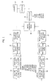
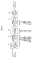
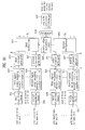
- a transmission end in a TDM system has a predetermined data rate in accordance with a reverse dedicate rate control, and generates a code symbol having a demanded interleaver length in accordance with the data rate. For this, a code symbol of the data to be newly transmitted and a code symbol of the data to be retransmitted are generated separately, and then the generated symbols are multiplexed in due time. Thereafter, a transmission system undergoes through a modulation process and a spreading process. In this case, the retransmission packet and the packets for new transmission use one common Walsh code and are transmitted through one common physical channel. Such a process is explained in detail as follows by referring to FIG. 1.
- FIG. 1 illustrates a functional block diagram of generating a transmission signal using a TDM system according to a first embodiment of the present invention, in which a count of retransmission for an error-occurring packet is limited to 1 by a transmission end.
- a system of generating a transmission signal using TDM includes CRC & tail bit adding blocks 10 and 14 adding CRC(cyclic redundancy code) for an error check and a tail bit to data to be newly transmitted or data of the previously transmitted data to be retransmitted, turbo encoders 11 and 15 encoding outputs of the blocks 10 and 14 into turbo codes of 1/5 code rate, first and second symbol rearrangement blocks 12 and 16 rearranging orders of encoded code symbols so as to divide the encoded code symbols into redundancy codes to be transmitted and redundancy codes not to be transmitted, respectively, symbol repetition or pruning blocks 13 and 17 generating code symbol streams having demanded lengths by symbol repetition or pruning of the rearranged code symbols(i.e.
- the transmission end has generation blocks each of which includes the CRC & tail bit adding block 10 or 14 to generate a new transmission packet to transmit new information and a retransmission packet, the turbo encoder 11 or 15, the interleaver 19, and the symbol repetition or pruning block 13 or 17.
- the generation blocks increase in proportional to a count of retransmission of random data.
- the CRC & tail bit adding block 10 or 14 adds the CRC for the error check and the tail bit to an information bit the receiving end wants to transmit.
- the turbo encoder 11 or 15 encodes the bit stream to which the CRC and tail bit are added into the turbo code having the 1/5 code rate.
- the first or second symbol rearrangement block 12 or 16 rearranges the order of the code symbols encoded into the turbo code. Namely, the symbol rearrangement blocks 12 and 16 rearrange the orders of the input code symbols so as not to carry out the interleaving in order to change a bust error into a random error as a channel interleaver of the related art but to support an incremental redundancy effectively.
- the orders of the code symbols are adjusted properly so as to divide the currently generated transmission signal into the redundancy code included in the new transmission packet to be transmitted and the other redundancy code included in the retransmission packet to be transmitted(the redundancy code failing to be included in the previous transmission signal).
- Such an operation of the symbol rearrangement block 12 or 16 enables a symbol repetition or pruning process of a next stage to be executed with ease.
- the symbol repetition or pruning block 13 or 17 symbol-repeats or prunes the order-rearranged code symbols as many as a predetermined count of symbols in order to meet a count of the encoded symbols with transmission energy allocated to the new transmission and the retransmission respectively.
- the series connection block time-multiplexes the respective symbols symbol-repeated or pruned by the symbol repetition or pruning blocks 13 and 17 so as to generate one stream.
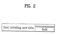
- Such a generated stream as shown in FIG. 2, fills its upper field with the code symbols representing the new information and its lower field with the code symbols consisting of the redundancy codes failing to be transmitted in the previous transmission signal.
- the interleaver 19 interleaves the respective code symbols in the upper and lower fields in the above-filled code symbols.
- the code symbols are modulated by the modulator 20, and then spread by the spreader 21 using one Walsh code.
- Table 1 illustrates the energy allocating amount for a reverse link HARQ system constructed using TDM on the assumption that the transmission end allows the retransmission once. This example assumes that the retransmission energy is allocated in a manner that only 25% of the receiving energy for the initial transmission energy of the corresponding retransmission data is basically received on retransmission. R/eng. N/eng.
- a set of the data rate enabling to be adjusted by the dedicate rate control consists of 8 elements of ⁇ 9.6kbps, 19.2kbps, 38.4kbps, 76.8kbps, 153.6kbps, 307.2kbps, 614.4kbps, 1024kbps ⁇ .
- a lower field of a transmission signal at the point of determining the retransmission includes code symbols containing a redundancy code failing to be transmitted by the previous transmission signal.
- 1/4 of the receiving energy for the initial transmission energy of the corresponding retransmission energy, as shown in Table 1 is allocated to the energy allocated to the code symbols.
- energy for the incremental redundancy code of the retransmission data is allocated in the first place as well as the rest energy is allocated to the newly transmitted data.
- the sum of the newly transmitted data and the transmission energy allocated to the retransmitted data will not to exceed the transmission energy determined by the data rate control.
- the initially transmitted packet is transmitted at a speed of 76.8kbps and at a time point of re-transmitting the packet, the mobile station is allowed to transmit with a speed of 153.6kbps by a reverse link dedicate rate control.
- the retransmission energy is adjusted so that the receiving energy of retransmitted packet will be 25% of the receiving energy for the initial transmission energy of the data to be retransmitted.
- the rest energy corresponds to 134.4kbps, and such a data rate fails to exist in the previous data rate set.
- the transmission sped of the newly transmitted code symbols is set up as 76.8kbps and repetition of the code symbols is carried out so as to match the transmission speed of 134.4kbps.
- the code symbols having the energy amounting to R are repeated or the code symbols having the energy amounting to P are punctured.
- R(repetition energy) or P(puncturing energy) means that the corresponding code symbols are symbol-repeated or punctured in order to fill the transmission energy corresponding to the data rate determined by the reverse link dedicate data rate control.
- the CDM system is applied to an embodiment of the present invention.
- the reverse supplemental channel 1 is always used as a physical channel for new transmission and the reverse supplemental channel 2 is always used as a physical channel for retransmission.
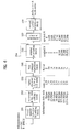
- FIG. 3 illustrates a functional block diagram for generating a transmission signal using a CDM system according to the first embodiment of the present invention.
- a system of generating a transmission signal using CDM is constructed as follows.
- a transmission end for each channel includes CRC & tail bit adding blocks 30 and 36 adding CRC(cyclic redundancy code) for an error check to an information bit a receiving end wants to transmit, turbo encoders 31 and 37 encoding outputs of the blocks 30 and 36 into turbo codes of 1/5 code rate, first and second interleavers 31 and 38 rearranging orders of encoded code symbols to prevent a transmission error so as to divide the encoded code symbols into redundancy codes to be transmitted and redundancy codes not to be transmitted, respectively, symbol repetition or pruning blocks 33 and 39 generating a length of a predetermined code symbol stream corresponding to transmission energy allocated to the data to be newly transmitted and the other data to be
- the CRC & tail bit adding block 30 or 36 adds the CRC for the error check and the tail bit to the information bit(data to be newly transmitted or be retransmitted) to be transmitted to the receiving end.
- the turbo encoder 31 or 37 encodes the bit stream to which the CRC and tail bit are added into the turbo code having the 1/5 code rate.
- the first or second interleaver 32 or 38 rearranges the order of the code symbols encoded into the turbo code. Namely, the interleavers 32 and 38 change a bust error into a random error as a channel interleaver of the related art as well as the order of the encoded symbols is properly adjusted so as to distinguish the redundancy code, which is to be contained in the data to be newly transmitted or fails to be transmitted to the previously transmitted data.
- the symbol repetition or pruning block 33 or 39 symbol-repeats or prunes the rearranged code symbols as many as a predetermined count of symbols in order to meet a count of the encoded symbols with transmission energy allocated to the new transmission and the retransmission respectively.
- the code symbols are modulated by the modulator 34 or 40, and then spread to the corresponding Walsh code by the spreader 35 or 41 so as to be transmitted to the receiving end through the reverse supplemental channel 1 and the reverse supplemental channel 2.
- portions of the code symbols, which are retransmitted through the reverse supplemental channel 2, except the redundancy code having been used for the original transmission are manipulated to be transmitted, thereby enabling to reduce an effective code rate through code combining in the receiving end.
- the reverse supplemental channel 2 is allocated to a physical channel for the retransmission to the packet from which NAK is generated, and then the Walsh code for this channel is allocated independently.
- a code multiplexing method using the allocated Walsh code may be considered.
- Table 2 illustrates, when a count of retransmission is limited to 1, the normalized energy allocated to a code symbol for the newly transmitted data or a code symbol including an incremental redundancy code for the data to be retransmitted in a reverse link HARQ system using CDM, where 'channel 1' or 'channel 2' indicates one of the reverse supplemental channels.
- Table has the same assumption of Table 1. Namely, This example 2 assumes that a transmission power level on retransmission is determined in a manner that only 25% of the receiving energy for the initial transmission energy of the corresponding retransmission data becomes the receiving energy on retransmission.
- a data rate set usable for the reverse supplemental channel 2 is ⁇ 2.4kbps, 4.8kbps, 9.6kbps, 19.2kbps, 38.4kbps, 76.8kbps, 153.6kbps, 307.2kbps ⁇ .
- the energy usable for the data to be retransmitted is represented by ⁇ 0.25, 0.5, 1, 2, 4, 8, 16, 32 ⁇ .
- the energy for the newly transmitted data is the same case of the previous reverse supplemental channel 1, i.e. ⁇ 1, 2, 4, 8, 16, 32, 64, 107 ⁇ .
- the data rate of the newly transmitted data is 38.4kbps
- an error occurs in the packet transmitted to the receiving end at this speed
- NAK for the corresponding packet is transmitted to the transmission end from the receiving end. Therefore, assuming that an allowable data rate by the reverse link dedicate rate control is 153.6kbps at the time point of determining the retransmission, the transmission energy of 9.6kbps is allocated to the code symbols for the data to be retransmitted on retransmission.
- the transmission energy of the retransmission is allocated so that 25% of the receiving energy for the initial transmission energy of the corresponding retransmission data becomes the receiving energy on the retransmission.
- the remaining energy after the allocating for the code symbols including the incremental redundancy code is allocated to the code symbols for the newly transmitted data.
- the data rate for the code symbols of the newly transmitted data can be determined as 76.8kbps or 153.6kbps.
- Such an additional energy is allowable so that the terminal enables to select the data rate for the reverse supplemental channel 1.
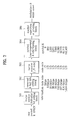
- FIG. 4 illustrates a device block diagram of a process of generating a transmission signal using the CDM system according to the first embodiment of the present invention.
- the reverse supplemental channels (hereinafter abbreviated R-SCH1 and R-SCH2) together with other channels R-PICH, R-DCCH, R-RICH, R-FCH, R-CQICH, and R-ACKCH are divided into I channel and Q channel respectively.
- the R-SCH1 and R-SCH2 together with the R-PICH, R-DCCH, and R-RICH are divided into the I channel
- the R-SCH1 and R-SCH2 together with the R-FCH, R-CQICH, and R-ACKCH are divided into the Q channel.
- the R-SCH2 is not used, the R-CCCH or REACH is transmitted.
- the code symbols of the respective channels included in the I or Q channel are transferred to the respective relative gain parts 50a 50b so as to further include relative gains, and then synthesized as one code symbols for the I and Q channels by adders 51a and 51b, respectively. These synthesized code symbols are called I channel data and Q channel data.
- the I or Q channel data is multiplied by a code resulted from multiplying an I channel sequence(60) by a long code generated from a long code generator 61(one of the adders 52a and 52b).
- a code which is delayed by an one-chip delayer 61 from the generated long code is multiplied by a Q channel sequence(59), detected by a decimator 58 by 1/2 chip unit so as to be multiplied by a Walsh cover 57, and then multiplied by the I or Q channel data(the other adder 52a or 52b.
- the code symbols, which are generated from being multiplied by the I channel data, and the other code symbols, which are generated from being multiplied by the Q channel data, in the finally multiplied symbols are synthesized by each adder 53a or 53b, band-passed by a first or second baseband filter 54a or 54b, multiplied by a carrier wave cos2nfct or sin2 ⁇ fct(55a,55b) so as to be synthesized by an adder 53c, and then transferred to a gain part 56 to include more gain so as to generate a final transmission signal S(t).
- a second embodiment according to the present invention in applying HARQ to a reverse link, proposes a method of adjusting transmission energy on transmission, in which a packet receiving NACK from a receiving end due to poor receiving status should be received with a predetermined portion of energy less than the receiving energy for the initial transmission energy of the packet on retransmission.
- the second embodiment according to the present invention proposes a method of optimizing a packet throughput of a reverse link using a spare energy space, which is provided by using such an energy reduction method on retransmission, for the transmission of a new packet.
- the second embodiment according to the present invention proposes a method of combining the energy reduction automatic retransmission technique with a data dedicate rate control technique for a reverse traffic.
- the second embodiment according to the present invention proposes uses a technique of adjusting a traffic energy level of the packet to be retransmitted in a manner that a receiving energy level at a base transceiver system of the retransmitted packet should become a predetermined portion compared to the receiving energy level of an initial transmission packet of the packet to be retransmitted.
- the base transceiver system enables to use energy amounting to (1+ ⁇ ) for a decoding process by combining the receiving energy of the packet to be newly transmitted with the receiving energy of the packet to be retransmitted.
- the fact that it is able to adjust the energy level of the packet to be retransmitted to an amount what we demand means that a pilot channel of the reverse link undergoes a reverse link energy control.
- the energy level of the reverse link pilot channel undergoes a power control by the base transceiver system so as to keep a constant level.
- energy gain values of other channels of the reverse link are adjusted so as to have a constant ratio to a transmission energy level of the pilot channel.
- the method used by the present invention adjusts a traffic to pilot power ratio G Re-Tx to be used for retransmitting the packet into ⁇ G first .
- the receiving energy of the retransmitted packet received by the base transceiver system will be 100 ⁇ % of the receiving energy of the initially transmitted packet of the retransmitted packet.
- a value of ⁇ is currently considered as one of 0.5, 0.25, and 0.125.
- the transmission energy for the retransmission packet is adjusted so that the receiving energy of the retransmitted packet received by the base transceiver system becomes 25% of the receiving energy of the initially transmitted packet.
- spare transmission energy is attained at the time point of the retransmission.
- the above-attained spare transmission energy is used for the transmission of a new packet, thereby enabling to increase a data throughput of the reverse link.
- the present invention uses a method of multiplexing the retransmission of the packet to which NACK is transmitted by the receiving end and the transmission of the new packet.
- CDM(code division multiplexing) and TDM(time division multiplexing) are considered for multiplexing the retransmission packet and new packet.
- a channel for packet transmission of the reverse link is called a reverse packet data channel(R-PDCH).
- the R-PDCH is constructed with two kinds of sub-channels, R-NPDCH(reverse new packet data channel) used for transmitting a new packet and R-RPDCH(reverse retransmission packet data channel) for transmitting a retransmitted packet.
- the two sub-channels are multiplexed using CDM or TDM.
- the R-NPDCH and R-RPDCH are transmitted on two physical channels independent reciprocally using different Walsh codes.
- the retransmission and the new transmission are multiplexed in due time on one physical channel using one Walsh code.
- FIGs. 5 to FIGs. 8 illustrate a transmission chain construction considering CDM.
- FIG. 5 and FIG. 6 illustrate transmission chain constructions of the respective channels R-RPDCH and R-NPDCH considering a chase combining in the HARQ system.
- FIG. 5 illustrates a block diagram of an example for a transmission chain construction of R-NPDCH for a newly transmitted packet according to a second embodiment of the present invention.
- FIG. 6 illustrates a block diagram of an example for a transmission chain construction of R-RPDCH for the retransmitted packet transmission according to the second embodiment of the present invention.
- the R-NPDCH and R-RPDCH construct transmission chains including frame quality indicator bit adding blocks 101 and 201, reserved & tail bit adding blocks 101 and 202, turbo encoders(1/4 and 1/2 rates) 103 and 203, first symbol repetition blocks 104 and 205, symbol puncturing blocks 105 and 206, channel interleavers 106 and 207, and second symbol repetition blocks 107 and 208, respectively.
- the first symbol repetition block/symbol puncturing block 104/105 and the first symbol repetition block/symbol puncturing block 205/206 construct rate matching blocks 108 and 204, respectively.
- a frame quality indicator bit of 16 bits is added to a packet data transmitted from the upper. And, a tail bit and a reserved bit are added thereto. Then, the packet data undergoes a turbo encoding process.
- a rate matching process with a length of a channel interleaver to be used is carried out through symbol repetition and symbol puncturing processes.
- Each of the second symbol repletion blocks 107 and 208 should carry out a number of the repetition as much as a proper quantity according to a length of a Walsh code to be used in a modulation block(not shown in the drawing) and a Walsh cover block(not shown in the drawing) at a rear end.
- Such a construction is based on the assumption of the chase combining of type I in the combining process of the HARQ system.
- data transfer rates (0, 9.6kbps, 19.2kbps, 38.4kbps, 76.8kbps, 153.6kbps, 307.2kbps, 614.4kbps, 1024kbps) of R-NPDCH in case of using the chase combining or partial chase combining, effective code rates(1/2 or 1/4), repetition factors(2x, 1x, 0) of symbol, puncturing quantity(0, 4096) of symbol, lengths(1536, 1536, 3072, 6144, 12288, 24576, 24576, 36864) of the used channel interleaver, and the like.
- data transfer rates (0, 9.6kbps, 19.2kbps, 38.4kbps, 76.8kbps, 153.6kbps, 307.2kbps, 614.4kbps, 1024kbps) of R-RPDCH in case of using the chase combining or partial chase combining, effective code rates(1/2 or 1/4), repetition factors(2x, 1x, 0) of symbol, puncturing quantity(0, 6144, 12288, 12288, 28672) of symbol, lengths(1536, 1536, 3072, 6144, 6144, 12288, 12288, 12288) of the used channel interleaver, and the like.
- the data rate of the data to be retransmitted for the R-RPDCH has the same information data rate of the R-NPDCH used for the initially transmitted data of the data to be retransmitted.
- the transmission chain corresponding to 38.4kbps of the R-RPDCH is used on retransmission.
- the code rate of the turbo encoder 203 is the same of the R-NPDCH in FIG. 5.
- the chase combining is carried out on the transmission data rates to 76.8kbps with the turbo code of 1/4 code, but portions of the encoded code symbols are retransmitted for the data rates higher that 76.8kbps(i.e. 153.6kbps ⁇ 1034kbps). Therefore, the partial combining is carried out.
- FIG. 7 illustrates a block diagram of another example of a transmission chain construction of R-NPDCH for a newly transmitted packet according to the second embodiment of the present invention.
- FIG. 8 illustrates a block diagram of another example of a transmission chain construction of R-RPDCH for a retransmitted packet transmission according to the second embodiment of the present invention.
- the R-NPDCH and R-RPDCH construct transmission chains including frame quality indicator bit adding blocks 301 and 401, reserved & tail bit adding blocks 302 and 402, turbo encoders(1/5 rate) 303 and 403, symbol rearrangement & interleaving blocks 304 and 404, and symbol pruning or repetition blocks 305 and 405, respectively.
- a frame quality indicator bit of 16 bits is added to a packet data transmitted from the upper by the frame quality indicator bit adding block 301 or 401. And, a tail bit and a reserved bit are added thereto by the reserved & tail bit adding block 302 or 402. Then, the packet data undergoes a turbo encoding process by the turbo encoder 303 or 403.
- a redundancy code which is included in the packet to be newly transmitted so as to be transmitted, or a redundancy code(which has failed to be included in the previous transmission signal), which is included in the other packet to be retransmitted so as to be transmitted, is divided into by the symbol rearrangement & interleaving block 304 or 404, and an order of the symbols is properly adjusted so as to prevent a bust transmission error.
- symbol rearrangement & interleaving enables the next step of symbol repetition or pruning to be carried out with ease.
- Each of the symbol pruning & repletion blocks 305 and 405 carries out a number of the pruning or repetition as many as a count of the predetermined symbols of which order is rearranged so as to meet the count of the encoded symbols allocated to the newly transmitted or retransmitted packet.
- the R-NPDCH or R-RPDCH when the incremental redundancy combining process is considered, the R-NPDCH or R-RPDCH always uses the turbo encoder 303 or 403 of 1/5 code rate. Moreover, the symbol rearrangement & interleaving bocks 304 and 404 should be designed so as to carry out both roles of rearrangement(reordering) and channel interleavers of the code symbols for the incremental redundancy process.
- code rates of the turbo encoders 303 and 403 and interleaving lengths in accordance with the data transfer rates of the R-NPDCH and R-RPDCH are provided.
- the symbol rearrangement & interleaving block 404 of the R-RPDCH should follow the same interleaving regulation of the other symbol rearrangement & interleaving block 304 of the R-NPDCH.
- the orders of the rearranged symbols of the R-NPDCH and R-RPDCH after the interleaving are identical to each other.
- the code symbols, which will be transmitted in the R-RPDCH are transmitted in a manner of a wrap round system from the code symbol following the last code symbol having been transmitted form the R-NPDCH.
- the base transceiver system enables to make the minimum effective code rate when the packets to be newly transmitted and to be retransmitted are combined with each other.
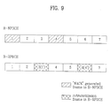
- FIG. 9 illustrates diagrams of multiplexed R-NPDCH for an initial transmission and R-RPDCH for a retransmission according to the second embodiment of the present invention.
- the terminal carries out the retransmission of the packet having NACK just at the moment of transmitting an (i+D) th packet, where it is assumed that D is a delay time(packet unit) of HARQ.
- the terminal having received NAK knows an initial transmission data rate R of the data to be retransmitted, whereby the data rate R-RPDCH will use for the retransmission of the initially transmitted data is a value having been already determined, R.
- the transmission power of the R-RPDCH is controlled so that the base transceiver system enables to receive a portion of the receiving energy for the initial transmission energy of the data to be retransmitted. If the T/P ratio of the R-NPDCH for the initially transmitted data of the data to be retransmitted is G first , a T/P ratio of the R-RPDCH at the time point of the retransmission is determined as ⁇ G first .
- the R-RPDCH will use a transmission chain corresponding to the transmission rate of R in FIG. 6 or FIG. 8 and the T/P ratio of ⁇ G first .
- FIG. 2 is a diagram assuming that D is 2. Namely, when the base transceiver system transmits NACK to the terminal for a packet-1 of the R-NPDCH, the terminal carries out the retransmission for the packet-1 having the NACK through the R-RPDCH at the transmission time point of a packet-3. In this case, the transmission speed of the packet-3 of the R-RPDCH becomes the same of the packet-1 of the R-NPDCH, and the T/P ratio is determined as ⁇ G first . Besides, the data transmission rate of the R-NPDCH is determined by the following process in accordance with the transmission energy which is allowed to the terminal to transmit at the retransmission time point.
- the base transceiver system maintains the reverse traffic transmission data rate of the terminal, or commands an RRC bit(which indicates increment or decrement) to the terminal through F-CRCCH(forward common rate control channel.
- the terminal having received such a command checks the RRC bit so as to determine the combining data rate to be transmitted in accordance with a command of the base transceiver system.
- the transmission power the terminal will use will be determined in accordance with the combining data rate.
- Such a combining data rate will be called an effective data rate R eff .
- the reverse link dedicate rate control carried out by the base transceiver system is to adjust the quantity of total power of the terminal which is received by the base transceiver system.
- the base transceiver system has a spare amounting to ⁇ and generates the RRC bit which will be transmitted to each terminal. Namely, on the assumption that the energy received from the terminal may be maximum (1+ ⁇ ) times bigger, the base transceiver system generates the RRC bit.
- the terminal should use the transmission power corresponding to the effective rate of R. Yet, since the spare amounting to ⁇ has been considered when the RRC was generated in the base transceiver system the station, the terminal uses R as the data rate of the R-NPDCH to currently transmit and the R-RPDCH multiplexes the two channels with the data rate of R and the transmission power of ⁇ G first .
- the terminal can use the energy as much maximum as 10log(1+ ⁇ ) dB additionally. If ⁇ is 0.25, the terminal can use the power of about 0.97dB, which is bigger than the power allowed by the base transceiver system, to the utmost additionally. If ⁇ is 0.5, the terminal can use the power of about 1.7dB, which is bigger than the power allowed by the base transceiver system, to the utmost additionally.
- the effective data rate at the retransmission time point increases so as to be twice faster than the initial transmission data rate of a predetermined packet after the delay time D of HARQ from the initial transmission of the predetermined packet.
- the R-RPDCH for the retransmission of the packet at the retransmission time point will use the data rate of R and the T/P of ⁇ G first .
- the terminal increases the transmission data rate of the currently transmitted R-NPDCH according to the command of the RRC bit.
- the increased transmission data rate of the R-NPDCH is 2R.
- the fact that the base transceiver system transmits the command of increasing the data rate means that the T/P ratio the terminal enables to transmit should be made twice bigger than the current value.
- the terminal can use the energy as much maximum as 10log(1+ ⁇ /2)dB additionally. If ⁇ is 0.25, the terminal can use the power of about 0.51dB, which is bigger than the power allowed by the base transceiver system, to the utmost additionally. If ⁇ is 0.5, the terminal can use the power of about maximum 0.97dB, which is bigger than the power allowed by the base transceiver system, to the utmost additionally.
- the terminal receives the command of reducing the data rate so as to be lower than that of the initial transmission of the packet at the retransmission time point after the delay time D of HARQ from the initial transmission time point of the predetermined packet.
- the terminal carries out the retransmission through the R-RPDCH for the retransmission of the packet using the T/P value of 0.5*G first .
- the transmission of the R-NPDCH for the data to be newly transmitted is not carried out. If the terminal receives the command of reducing the data rate down to 1/4 of the value of the initial transmission of the packet at the retransmission time point after the delay time D of the HARQ, the terminal carries out just the transmission of the packet using the ⁇ value of 0.25.
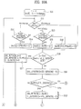
- the algorithm of the combination of the HARQ system and the dedicate data rate control system can be expressed through the flowcharts like FIG. 10A and FIG. 10B.
- FIG. 10A and FIG. 10B illustrate flowcharts of examples for the systems of a reverse traffic transmission data rate control of a base transceiver system and an energy control according to the second embodiment of the present invention.
- the terminal if having data to transmit, always starts transmitting the data at the transmission speed of 9.6kbps without the approval of the base transceiver system.
- R eff (-1) is defined as 9.6kbps in FIG. 10A and FIG. 10B.
- the terminal undergoes a data transmission speed dedicate control from the base transceiver system(S10).
- the terminal receives the RRC bit(reverse rate control) generated from the base transceiver system so as to determine an effective data transmission speed R eff (i) according to the RRC bit(S11).
- the terminal Even if the terminal receives a command of increasing the transmission speed from the base transceiver system through the RRC bit, the terminal enables to maintain or reduce the effective data transmission speed in accordance with its status(S12 or S13).
- the terminal Likewise, receiving a command of maintaining the transmission speed from the base transceiver system, the terminal enables to reduce the effective data transmission speed in accordance with its status.
- the terminal always has to reduce the effective data transmission speed.
- the base transceiver system does not transmit the command of reducing the data transmission speed to the terminal of using the effective data transmission speed of 9.6kbps.
- the terminal updates the effective transmission speed R eff (i) in accordance with its status and the reverse link dedicate data transmission control(S14, S15, or S16). For instance, the corresponding terminal increases the data transmission speed twice higher than R eff (i-1) and decrease the data transmission speed 1/2 less than R eff (i-1)(S16).
- the terminal checks whether ACK/NACK for an (i-D) th R-NPDCH packet is transmitted from the bas station(S18).
- the terminal transmits R-NPDCH only for the data to be currently transmitted at the time point of transmitting the i th packet.
- the data transmission speed of R-NPDCH for the data to be currently transmitted becomes R eff (i).
- DR_RPDCH(i) as a data rate of the R-RPDCH is 0 at the time point of transmitting the i th packet
- DR_NPDCH(i) as a data rate of R-NPDCH for the data to be currently transmitted at the time point of the i th packet uses the previous R eff (i).
- G_RPDCH(i) as a T/P ratio of R-NPDCH for the data to be currently transmitted becomes 0 at the time point of transmitting the i th packet(S17). Therefore, the terminal transmits the R-NPDCH and prepares a transmission of the next packet(S25).
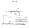
- the terminal When the terminal receives a NACK command for the (i-D) th R-NPDCH packet(S18), the DR_RPDCH(i) is updated as a value of the DR_NPDCH(i-D)(S19). And, the terminal compares the updated effective data transmission speed R eff (i) to the DR_NPDCH(i-D) of the transmission speed of R_NPDCH at the time point of transmitting the (i-D) th packet(S20).
- the DR_NPDCH(i) of the transmission speed of the R_NPDCH to be transmitted at the time point of transmitting the i th packet is set up as R eff (i)(S22).
- the transmission speed of the R-RPDCH is the value previously determined as a speed transmitted in the (i-D) th R-NPDCH packet.
- the terminal transmits a new packet using the R-NPDCH transmission chain corresponding to the determined transmission speed in FIG. 5 or FIG. 7.
- the transmission chain of R-RPDCH in FIG. 6 or FIG. 8 corresponding to the data transmission speed in the (i-D) th R-NPDCH packet.
- the transmission power of the R-RPDCH is adjusted so that the receiving energy of the retransmission packet received by the base transceiver system becomes ⁇ times to the initial receiving energy of the corresponding data to be retransmitted.
- ⁇ G_NPDCH(i-D) is used as the T/P(traffic to pilot power) ratio of the R-RPDCH, G_RPDCH(i)(S22).
- the DR_NPDCH(i) which is the transmission data rate of the R-NPDCH to be transmitted at the time point of transmitting the i th packet is set up as 0(S23 or S24).
- all available power is used for the retransmission packet.
- used is the transmission chain of R-RPDCH in FIG. 6 or FIG. 8 corresponding to the data transmission rate in the (i-D)th R-NPDCH packet.
- the transmission power of R-RPDCH is adjusted so as to use all available power at the very time point.
- an initial transmission data rate for a packet is 76.8kbps and that a delay time of HARQ is a delay time of 3 packets.
- the terminal has received RRC bits of (down, down, up) from the base transceiver system for the delay time of the three packets.
- ⁇ is assumed to be 0.25.
- an effective data transmission rate available for the terminal to use becomes 38.4kbps at a time point of retransmission.
- a transmission data rate of R-RPDCH becomes the data rate of the initially transmitted packet, 76.8kbps.
- transmission energy to be used for retransmission of packet will the entire energy allowed by the effective data rate determined at the time point of retransmission.
- RRC bits up, up, down
- an effective data transmission rate available for the terminal to use becomes 153.6kbps at a time point of retransmission.
- the effective transmission data rate is bigger than the initial transmission data rate of the packet, whereby the transmission of the newly transmitted current packet and the transmission of the retransmitted packet at the time point of retransmission are time-multiplexed or code-multiplexed.
- the transmission data rate of the newly transmitted packet becomes the effective transmission data rate, 153.6kbps.
- the transmission data rate of R-RPDCH for the retransmission packet will be 76.8kbps and a T/P ratio will be 0.25 times of the T/P ratio having been used in the initial transmission of the packet to be retransmitted.
- an energy reduction factor ⁇ is 0.5, when the method of multiplexing R-NPDCH and R-RPDCH using the flowcharts in FIG. 10A and FIG. 10B are used, there may be a slight chance to bring about a problem in the data rate control.
- FIG. 11B may be used instead of using the flowcharts in FIG. 10A and FIG. 10B.
- FIG. 11A and FIG. 11B illustrate flowcharts of another examples for the systems of a reverse traffic transmission data rate control of a base transceiver system and an energy reduction reverse link automatic retransmission, in which the energy reduction factor ⁇ is 0.5.
- a data rate of R-NPDCH for a packet to be newly transmitted currently is set up as an effective data rate R eff (i) in FIG. 10A and FIG. 10B.
- the data rate of R-NPDCH for the packet to be newly transmitted currently is set up as 1/2 of the effective data rate R eff (i) on a step S33 in FIG. 11A and FIG. 11B.
- the energy and data rate controls using the TDM system are carried out as follows.
- code symbols for new transmission and retransmission are separated for time-multiplexing, modulation, and diffusion so as to be transmitted.
- packets for retransmission and new transmission are transmitted through one physical channel using one Walsh code.
- the TDM system can be realized in accordance with the construction in FIG. 1.
- the ACK and NAK commands are managed by either a base transceiver system(hereinafter abbreviated BTS) or a base station controller(hereinafter abbreviated BSC).
- BTS base transceiver system
- BSC base station controller
- BSC controls ACK and NAK
- all BTSs in an active set comes into transmission of the demodulated packets to BSC. Therefore, BSC generates an ACK signal if there exists at least one good packet or a NAK signal if all the packets transmitted from BTS are bad, so s to transmit such signals to all BTSs in the active set.
- all BTSs begin to transmit the same ACK or NAK signals to a terminal. If such a system is used, the terminal enables to carry out a soft combining on the ACK and NAK signals so as to increase the reliance for the ACK and NAK signals. Unfortunately, a performance delay time of HARQ increases as well.
- BTS directly handles the ACK and NAK signals, there occurs no delay problem between BSC and BTS. Yet, all BTSs in the active set may generate ACK or NAK signals which are different respectively, whereby the terminal is unable to apply the soft combining to these signals.
- the retransmission for the corresponding packet fails to occur in the terminal.
- a forward channel to transmit ACK and NACK signals there are various methods of forming a forward channel to transmit ACK and NACK signals to a terminal.
- One method is to form one independent physical channel for the transmission of ACK and NAK signals.
- the other method is to use both of the channel for reverse dedicate rate control and the physical channel in common.
- one independent physical channel is formed to transmit ACK and NAK signals.
- various users are preferred to be accommodated in one common channel instead of using the respective physical channels for ACK and NAK signals transferred to the respective terminals.
- a channel for a dedicate rate control is required.
- RRC(reverse rate control) information is transferred to the terminals which are transmitting packet data through the current reverse link channel by packet unit. And, it is able to multiplex this channel into one common physical channel with ACK/NAK signals.
- Such a multiplexing enables to save Walsh code.
- FIG. 12 illustrates a block diagram of a channel for ACK/NACK transmission and a channel multiplexing a reverse rate control channel according to the second embodiment of the present invention, in which the corresponding channels are multiplexed using one Walsh code.
- blocks for a reverse common control channel includes repetition blocks 601, 605, 609, and 613, signal point mapping blocks 602, 606, 610, and 614, channel gain parts 603, 607, 611, and 615, multiplexers 604 and 612, a relative offset calculation part 608, a decimator 616, and a long code generator 617.
- RRC bits for a reverse data rate control are transmitted to a branch-I and ACK or NACK bits are transmitted to a branch-Q, and vice versa.
- This above-generated channel will be called F-CRCCH(forward common reverse control channel).
- the branch-I and branch-Q define the respective channels having a phase difference, which generally means a vertical phase difference.
- F-CRCCH forward common rate control channel
- F-CACKCH forward common acknowledgement channel
- F-CRCCH enables accommodate control information for 24 or 48 users.
- ACK or NACK bits are repeated 8 times.
- positions of the repeated bits for more diversity gain are arranged with uniform intervals for total 20ms packet time. Namely, if one packet is divided into 16 power control groups(PCG), the control information is transmitted once every 2 PCG.
- control information is repeated four times and transmitted every 4 PCG.
- the repetition blocks 610, 605, 609, and 613 use the ACK/NACK bit or the respective rate control bits for a plurality of users as their inputs, and repeat the bits for the repeated transmission for 20 ms packet time every PCG section.
- Each of the signal point mapping blocks 602, 606, 610, and 614 carries out mapping on 0 into +1, 1 into -1, and none(no transmission bit) into 0 among the repeated bit values. If the number of the users is 24, the number of symbols at a point A or point C through the signal point mapping blocks 602, 606, 610, and 614 output one symbol every 2 PCG sections. And, if the number of users is 48, one symbol is outputted every 4 PCG sections.
- the channel gain parts 603, 607, 611, and 615 adjust channel gains of the respective bits for the corresponding users.
- the channel gain parts allocate the different channel gain values for the corresponding users, respectively(point B or point D).
- the multiplexers 604 and 612 carry out multiplexing on the rate control bits of the respective users of which gains are adjusted or ACK/NACK bits of the respective users. In this case, the multiplexers 604 and 612 adjust offset values of the respective users in accordance with the offset value provided by the relative offset calculation part 608.
- the long code generator 617 generates long codes which are different in accordance with a long code mask for the reverse control channel, and the decimator 616 detects the long codes by chip unit so as to provide the relative calculation part 608 with the detected long codes. Accordingly, the relative offset calculation part 608 calculates the offset values of the respective users so as to provide the multiplexers 604 and 612 with the calculated offset values.
- the reverse channel informing the data rate of the reverse link is generated by the following manner.
- R-NPDCH channel is a channel of a variable data rate in which the data rate can vary basically.
- a reverse rate indication channel (hereinafter abbreviated RRI channel), which informs the data rate of the current R-NPDCH, exists in the reverse link.
- RRI channel a reverse rate indication channel
- the data rate for R-RPDCH of the present invention is already known to the base transceiver system(BTS), whereby clear indication is unnecessary.
- BTS base transceiver system
- additional information of one bit is necessary for informing whether the transmission of a new packet and the other transmission of a packet, in which NACK occurs, are multiplexed reciprocally.
- the present invention designs the HARQ system effective in the reverse link of the present 1x-EV DV, thereby enabling to increase an effect of data throughput of the reverse link.
- the present invention enables to design an effective combination of the reverse link dedicated rate control method and the HARQ system, which is enabled by using the HARQ system using Type-II or Type-III using an incremental redundancy system, or the chase combining or partial combining of the Type-I HARQ system.
- the HARQ system of the reverse link enables to use the method of reducing the receiving energy of the retransmitted packet down to the energy received at the initial transmission. Such a method can be applied to the transmission for the new packet using the spare energy space, thereby increasing the packet throughput of the reverse link.
Landscapes
- Engineering & Computer Science (AREA)
- Computer Networks & Wireless Communication (AREA)
- Signal Processing (AREA)
- Quality & Reliability (AREA)
- Detection And Prevention Of Errors In Transmission (AREA)
- Mobile Radio Communication Systems (AREA)
- Communication Control (AREA)
Applications Claiming Priority (4)
| Application Number | Priority Date | Filing Date | Title |
|---|---|---|---|
| KR1020010014696A KR100753500B1 (ko) | 2001-03-21 | 2001-03-21 | 역방향 링크에서의 하이브리드 자동 재송 요구 방식을이용한 링크 적응 방법 및 이를 위한 시스템 |
| KR2001014696 | 2001-03-21 | ||
| KR2001055518 | 2001-09-10 | ||
| KR1020010055518A KR100873117B1 (ko) | 2001-09-10 | 2001-09-10 | 하이브리드 자동 재송 요구 방식을 이용한 패킷 재전송 방법 |
Publications (3)
| Publication Number | Publication Date |
|---|---|
| EP1244240A2 true EP1244240A2 (de) | 2002-09-25 |
| EP1244240A3 EP1244240A3 (de) | 2007-05-02 |
| EP1244240B1 EP1244240B1 (de) | 2010-11-10 |
Family
ID=26638901
Family Applications (1)
| Application Number | Title | Priority Date | Filing Date |
|---|---|---|---|
| EP02006286A Expired - Lifetime EP1244240B1 (de) | 2001-03-21 | 2002-03-20 | Wiederübertragung von daten durch eine Rückwärtsverbindung in einem Paketdatenübertragungssystem mit automatischer Wiederholungsaufforderung |
Country Status (5)
| Country | Link |
|---|---|
| US (1) | US7580427B2 (de) |
| EP (1) | EP1244240B1 (de) |
| CN (1) | CN100455036C (de) |
| AT (1) | ATE488064T1 (de) |
| DE (1) | DE60238225D1 (de) |
Cited By (13)
| Publication number | Priority date | Publication date | Assignee | Title |
|---|---|---|---|---|
| WO2004017557A1 (en) * | 2002-08-19 | 2004-02-26 | Qualcomm Incorporated | Energy retransmission minimising method and apparatus thereof in arq communications |
| WO2004042992A1 (en) * | 2002-11-05 | 2004-05-21 | Nokia Corporation | Method, device and system for determining a transmission power for arq related re-transmissions |
| EP1455492A2 (de) | 2003-03-05 | 2004-09-08 | Samsung Electronics Co., Ltd. | Verfahren und Vorrichtung zum Steuern der Rückverkehrsrate in einem Mobilkommunikationssystem |
| DE10315249A1 (de) * | 2003-04-03 | 2004-11-18 | Rohde & Schwarz Gmbh & Co. Kg | Verfahren und Messgerät zum Ermitteln einer Fehlerrate ohne Incremental Redundancy |
| WO2005022883A2 (en) | 2003-09-03 | 2005-03-10 | Lg Electronics Inc. | Method of controlling transmission power of retransmission packet and mobile terminal using the same |
| WO2005050866A1 (de) * | 2003-11-17 | 2005-06-02 | Siemens Aktiengesellschaft | Verfahren zum senden von daten von einer mobilstation an eine basisstation |
| WO2005050903A1 (de) * | 2003-11-17 | 2005-06-02 | Siemens Aktiengesellschaft | Verfahren zum senden von daten von einer mobilstation an eine basisstation |
| WO2005055486A3 (en) * | 2003-12-05 | 2005-09-01 | Lg Electronics Inc | Reverse data rate controlling method in mobile communication system |
| EP1583272A1 (de) * | 2004-04-01 | 2005-10-05 | Matsushita Electric Industrial Co., Ltd. | Interferenzverminderung bei Wiederholungsübertragungen im Aufwärtskanal |
| EP1420541A3 (de) * | 2002-11-14 | 2006-05-17 | Hughes Network Systems, LLC | Systeme und Verfahren zur Übertragung von Internetprotokolldaten über Satellit |
| KR100656329B1 (ko) * | 2004-01-09 | 2006-12-12 | 후지쯔 가부시끼가이샤 | 전송 장치, 전송 제어 프로그램, 및 전송 방법 |
| JP2007531432A (ja) * | 2004-04-01 | 2007-11-01 | 松下電器産業株式会社 | 再送に対する干渉制限 |
| EP1618753A4 (de) * | 2003-04-30 | 2011-03-09 | Motorola Mobility Inc | Harq-ack/nak-codierung für eine kommunikationseinrichtung während der soft-weiterreichung |
Families Citing this family (48)
| Publication number | Priority date | Publication date | Assignee | Title |
|---|---|---|---|---|
| US7379416B2 (en) * | 2002-03-13 | 2008-05-27 | Lsi Logic Corporation | Forward packet data channel with parallel sub-packets |
| KR100932482B1 (ko) * | 2002-05-03 | 2009-12-17 | 엘지전자 주식회사 | 셀 또는 섹터 스위칭을 위한 프레임 전송 방법 |
| KR100584170B1 (ko) * | 2002-07-11 | 2006-06-02 | 재단법인서울대학교산학협력재단 | 터보 부호화된 복합 재전송 방식 시스템 및 오류 검출 방법 |
| AU2003279930A1 (en) * | 2002-10-09 | 2004-05-04 | Acorn Packet Solutions, Llc | System and method for rate agile adaptive clocking in a packet-based network |
| US20040120349A1 (en) * | 2002-11-14 | 2004-06-24 | Hughes Electronics | Systems and methods for transmitting internet protocol data via satellite |
| US7720043B2 (en) * | 2002-11-20 | 2010-05-18 | Qualcomm Incorporated | Use of idle frames for early transmission of negative acknowledgement of frame receipt |
| US6996763B2 (en) * | 2003-01-10 | 2006-02-07 | Qualcomm Incorporated | Operation of a forward link acknowledgement channel for the reverse link data |
| US7155249B2 (en) * | 2003-01-10 | 2006-12-26 | Qualcomm Incorporated | Modified power control for hybrid ARQ on the reverse link |
| US8391249B2 (en) | 2003-02-18 | 2013-03-05 | Qualcomm Incorporated | Code division multiplexing commands on a code division multiplexed channel |
| US20040160922A1 (en) | 2003-02-18 | 2004-08-19 | Sanjiv Nanda | Method and apparatus for controlling data rate of a reverse link in a communication system |
| US7155236B2 (en) | 2003-02-18 | 2006-12-26 | Qualcomm Incorporated | Scheduled and autonomous transmission and acknowledgement |
| US7660282B2 (en) | 2003-02-18 | 2010-02-09 | Qualcomm Incorporated | Congestion control in a wireless data network |
| US7215930B2 (en) * | 2003-03-06 | 2007-05-08 | Qualcomm, Incorporated | Method and apparatus for providing uplink signal-to-noise ratio (SNR) estimation in a wireless communication |
| US8705588B2 (en) | 2003-03-06 | 2014-04-22 | Qualcomm Incorporated | Systems and methods for using code space in spread-spectrum communications |
| JP4224337B2 (ja) * | 2003-04-04 | 2009-02-12 | パナソニック株式会社 | 無線送信装置および無線送信方法 |
| EP2267930B1 (de) | 2003-04-10 | 2019-06-12 | Telefonaktiebolaget LM Ericsson (publ) | Verfahren und Vorrichtung zur Wiederübertragung |
| KR100964670B1 (ko) * | 2003-05-12 | 2010-06-22 | 엘지전자 주식회사 | 이동통신 시스템에서 데이터 레이트 제어 정보를 생성하는방법 |
| US8477592B2 (en) | 2003-05-14 | 2013-07-02 | Qualcomm Incorporated | Interference and noise estimation in an OFDM system |
| DE602004016745D1 (de) * | 2003-05-16 | 2008-11-06 | Matsushita Electric Industrial Co Ltd | Vorrichtung und verfahren zum senden und empfangen für ein kommunikationsnetz |
| US7146171B2 (en) * | 2003-05-30 | 2006-12-05 | Nokia Corporation | Method and apparatus providing enhanced reservation access mode for a CDMA reverse channel |
| US7466666B2 (en) * | 2003-06-18 | 2008-12-16 | Telefonaktiebolaget Lm Ericsson (Publ) | Forward ACK/NACK channel for CDMA system |
| US7817663B2 (en) * | 2003-07-14 | 2010-10-19 | Samsung Electronics Co., Ltd. | Method and apparatus for generating packet data to support multiple services in a wireless packet data communication system |
| US8489949B2 (en) | 2003-08-05 | 2013-07-16 | Qualcomm Incorporated | Combining grant, acknowledgement, and rate control commands |
| KR101009861B1 (ko) * | 2003-08-19 | 2011-01-19 | 삼성전자주식회사 | 이동통신 시스템에서의 데이터 전송 방법과 전송률 할당 방법 및 이를 위한 장치 |
| KR100712323B1 (ko) * | 2003-10-02 | 2007-05-02 | 삼성전자주식회사 | 패킷 통신 시스템에서 빠른 전송율 변화를 지원하는 역방향 전송율 스케쥴링 방법 및 장치 |
| EP1524791A3 (de) * | 2003-10-15 | 2008-02-13 | Samsung Electronics Co., Ltd. | Verfahren für die Steuerung der Paketrate in einem Mobilkommunikationssystem |
| JP4041450B2 (ja) * | 2003-10-23 | 2008-01-30 | ソニー・エリクソン・モバイルコミュニケーションズ株式会社 | 通信端末装置および通信方法 |
| US8570952B2 (en) * | 2004-04-29 | 2013-10-29 | Interdigital Technology Corporation | Method and apparatus for selectively enabling reception of downlink signaling channels |
| US7792048B2 (en) * | 2004-09-30 | 2010-09-07 | Alcatel-Lucent Usa Inc. | Outer loop power control in a communication system |
| CN1832392A (zh) * | 2005-03-11 | 2006-09-13 | 松下电器产业株式会社 | 多入多出系统中数据重传的方法和设备 |
| WO2006120524A1 (en) * | 2005-05-06 | 2006-11-16 | Nokia Corporation | Method, apparatus and computer program providing multi-carrieracknowledgment channel |
| EP1770895A1 (de) * | 2005-09-28 | 2007-04-04 | Koninklijke Philips Electronics N.V. | Übertragungsgeschwindigkeitsanpassung mit inkrementaler Redundanz |
| EP1770896A1 (de) | 2005-09-28 | 2007-04-04 | Koninklijke Philips Electronics N.V. | Verfahren, Vorrichtung und System zur Fehlerdetektion und selektiven Übertragungswiederholung |
| KR100729258B1 (ko) * | 2005-12-07 | 2007-06-18 | 엘지전자 주식회사 | 확장된 링크 적응화 기법을 제공하는 이동 통신 단말기 및그 방법 |
| EP1816776A1 (de) * | 2006-02-07 | 2007-08-08 | Alcatel Lucent | Einrichtung und Verfahren zur Unterdrückung impulsiver Störungen bei paketorientierter Übertragung |
| WO2007149047A1 (en) * | 2006-06-23 | 2007-12-27 | Panasonic Corporation | Re-transmission in a mimo communication system |
| US7661038B2 (en) * | 2006-10-09 | 2010-02-09 | Intel Corporation | Link adaptation for retransmission error-control technique transmissions |
| JP2008103991A (ja) * | 2006-10-19 | 2008-05-01 | Oki Electric Ind Co Ltd | データ伝送方法 |
| US7933372B2 (en) * | 2007-03-08 | 2011-04-26 | Freescale Semiconductor, Inc. | Successive interference cancellation based on the number of retransmissions |
| ES2563166T3 (es) * | 2007-03-19 | 2016-03-11 | Telefonaktiebolaget Lm Ericsson (Publ) | (H)ARQ para planificación semi-persistente |
| US8179915B2 (en) * | 2007-06-28 | 2012-05-15 | Lantiq Deutschland Gmbh | System and method for transmitting and retransmitting data |
| US8738981B2 (en) * | 2008-10-24 | 2014-05-27 | Qualcomm Incorporated | Method and apparatus for H-ARQ scheduling in a wireless communication system |
| US8266490B2 (en) * | 2009-04-08 | 2012-09-11 | Via Telecom, Inc. | Apparatus and method for reverse link transmission in an access terminal |
| US8665809B2 (en) * | 2009-06-15 | 2014-03-04 | Qualcomm Incorporated | Systems and methods for sending power control information |
| JP6180863B2 (ja) * | 2013-09-18 | 2017-08-16 | 株式会社東芝 | Icカード、携帯可能電子装置、及び、icカード処理装置 |
| CN106301662A (zh) * | 2015-05-14 | 2017-01-04 | 株式会社Ntt都科摩 | 数据发送和接收方法以及数据发送和接收设备 |
| CN111953623A (zh) * | 2020-07-31 | 2020-11-17 | 深圳市泛海检测认证有限公司 | 一种数据传输方法及系统 |
| US11662645B2 (en) * | 2020-09-09 | 2023-05-30 | Nokia Solutions And Networks Oy | Multi-stage probabilistic signal shaping |
Citations (1)
| Publication number | Priority date | Publication date | Assignee | Title |
|---|---|---|---|---|
| WO1999026371A1 (en) | 1997-11-13 | 1999-05-27 | Qualcomm Incorporated | Method and apparatus for time efficient retransmission using symbol accumulation |
Family Cites Families (19)
| Publication number | Priority date | Publication date | Assignee | Title |
|---|---|---|---|---|
| US5918002A (en) * | 1997-03-14 | 1999-06-29 | Microsoft Corporation | Selective retransmission for efficient and reliable streaming of multimedia packets in a computer network |
| AU751048B2 (en) * | 1997-05-30 | 2002-08-08 | Qualcomm Incorporated | Method and apparatus for providing error protection for over the air file transfer |
| US6084904A (en) * | 1997-07-25 | 2000-07-04 | Motorola, Inc. | Method and apparatus for adjusting a power control setpoint threshold in a wireless communication system |
| JP3286247B2 (ja) * | 1998-05-08 | 2002-05-27 | 松下電器産業株式会社 | 無線通信システム |
| KR100288375B1 (ko) | 1998-05-25 | 2001-06-01 | 윤종용 | 역방향링크와독립적인순방향링크의전력제어방법 |
| US6359877B1 (en) * | 1998-07-21 | 2002-03-19 | Telefonaktiebolaget Lm Ericsson (Publ) | Method and apparatus for minimizing overhead in a communication system |
| GB9821089D0 (en) * | 1998-09-30 | 1998-11-18 | Koninkl Philips Electronics Nv | Method for the communication of information and apparatus employing the method |
| US6367045B1 (en) * | 1999-07-01 | 2002-04-02 | Telefonaktiebolaget Lm Ericsson (Publ) | Bandwidth efficient acknowledgment/negative acknowledgment in a communication system using automatic repeat request (ARQ) |
| US6167273A (en) * | 1999-04-28 | 2000-12-26 | Nokia Mobile Phones Ltd. | Apparatus, and associated method, for effectuating power control to maintain desired QoS levels in the performance of a communication service |
| AU779378C (en) * | 2000-01-20 | 2005-02-24 | Apple Inc. | Hybrid ARQ schemes with soft combining in variable rate packet data transmission |
| JP3577253B2 (ja) | 2000-01-31 | 2004-10-13 | シャープ株式会社 | 無線通信装置およびその送信電力制御方法およびそれを用いた無線通信システム |
| EP2375612B1 (de) * | 2000-05-17 | 2013-01-23 | Panasonic Corporation | Hybride ARQ-Sendevorrichtung und -verfahren zur Paketdatenübertragung |
| JP4330767B2 (ja) | 2000-06-26 | 2009-09-16 | 株式会社エヌ・ティ・ティ・ドコモ | 自動再送要求を行う通信方法及び基地局装置 |
| US6977888B1 (en) * | 2000-09-14 | 2005-12-20 | Telefonaktiebolaget L M Ericsson (Publ) | Hybrid ARQ for packet data transmission |
| US6999430B2 (en) | 2000-11-30 | 2006-02-14 | Qualcomm Incorporated | Method and apparatus for transmitting data traffic on a wireless communication channel |
| US7120134B2 (en) * | 2001-02-15 | 2006-10-10 | Qualcomm, Incorporated | Reverse link channel architecture for a wireless communication system |
| KR100753500B1 (ko) | 2001-03-21 | 2007-08-31 | 엘지전자 주식회사 | 역방향 링크에서의 하이브리드 자동 재송 요구 방식을이용한 링크 적응 방법 및 이를 위한 시스템 |
| KR100381031B1 (ko) | 2001-04-18 | 2003-04-23 | 주식회사 하이닉스반도체 | 무선통신 시스템에서의 재전송 슬롯 결합 방법 및 그를이용한 데이터 수신 장치 및 방법 |
| US6898193B2 (en) | 2002-06-20 | 2005-05-24 | Qualcomm, Incorporated | Adaptive gain adjustment control |
-
2002
- 2002-03-20 AT AT02006286T patent/ATE488064T1/de not_active IP Right Cessation
- 2002-03-20 EP EP02006286A patent/EP1244240B1/de not_active Expired - Lifetime
- 2002-03-20 DE DE60238225T patent/DE60238225D1/de not_active Expired - Lifetime
- 2002-03-20 US US10/101,220 patent/US7580427B2/en not_active Expired - Lifetime
- 2002-03-21 CN CNB021079781A patent/CN100455036C/zh not_active Expired - Fee Related
Patent Citations (1)
| Publication number | Priority date | Publication date | Assignee | Title |
|---|---|---|---|---|
| WO1999026371A1 (en) | 1997-11-13 | 1999-05-27 | Qualcomm Incorporated | Method and apparatus for time efficient retransmission using symbol accumulation |
Cited By (29)
| Publication number | Priority date | Publication date | Assignee | Title |
|---|---|---|---|---|
| WO2004017557A1 (en) * | 2002-08-19 | 2004-02-26 | Qualcomm Incorporated | Energy retransmission minimising method and apparatus thereof in arq communications |
| US7089030B2 (en) | 2002-08-19 | 2006-08-08 | Qualcomm Incorporated | De-boosting in a communications environment |
| WO2004042992A1 (en) * | 2002-11-05 | 2004-05-21 | Nokia Corporation | Method, device and system for determining a transmission power for arq related re-transmissions |
| US7573860B2 (en) | 2002-11-05 | 2009-08-11 | Nokia Corporation | Method, device and system for determining a transmission power for ARQ related re-transmissions |
| EP1420541A3 (de) * | 2002-11-14 | 2006-05-17 | Hughes Network Systems, LLC | Systeme und Verfahren zur Übertragung von Internetprotokolldaten über Satellit |
| EP1455492A2 (de) | 2003-03-05 | 2004-09-08 | Samsung Electronics Co., Ltd. | Verfahren und Vorrichtung zum Steuern der Rückverkehrsrate in einem Mobilkommunikationssystem |
| EP1455492A3 (de) * | 2003-03-05 | 2010-04-07 | Samsung Electronics Co., Ltd. | Verfahren und Vorrichtung zum Steuern der Rückverkehrsrate in einem Mobilkommunikationssystem |
| US9967899B2 (en) | 2003-03-05 | 2018-05-08 | Samsung Electronics Co., Ltd | Method and apparatus for controlling an uplink transmission power ratio in a mobile communication system |
| DE10315249A1 (de) * | 2003-04-03 | 2004-11-18 | Rohde & Schwarz Gmbh & Co. Kg | Verfahren und Messgerät zum Ermitteln einer Fehlerrate ohne Incremental Redundancy |
| US7620871B2 (en) | 2003-04-03 | 2009-11-17 | Rohde & Schwarz Gmbh & Co. Kg | Method and measuring device for determining an error rate without incremental redundancy |
| EP1618753A4 (de) * | 2003-04-30 | 2011-03-09 | Motorola Mobility Inc | Harq-ack/nak-codierung für eine kommunikationseinrichtung während der soft-weiterreichung |
| WO2005022883A2 (en) | 2003-09-03 | 2005-03-10 | Lg Electronics Inc. | Method of controlling transmission power of retransmission packet and mobile terminal using the same |
| WO2005022883A3 (en) * | 2003-09-03 | 2005-06-09 | Lg Electronics Inc | Method of controlling transmission power of retransmission packet and mobile terminal using the same |
| US7372834B2 (en) | 2003-09-03 | 2008-05-13 | Lg Electronics Inc. | Method of controlling transmission power of retransmission packet and mobile terminal using the same |
| AU2004302746B2 (en) * | 2003-09-03 | 2009-07-30 | Lg Electronics Inc. | Method of controlling transmission power of retransmission packet and mobile terminal using the same |
| WO2005050903A1 (de) * | 2003-11-17 | 2005-06-02 | Siemens Aktiengesellschaft | Verfahren zum senden von daten von einer mobilstation an eine basisstation |
| WO2005050866A1 (de) * | 2003-11-17 | 2005-06-02 | Siemens Aktiengesellschaft | Verfahren zum senden von daten von einer mobilstation an eine basisstation |
| WO2005055486A3 (en) * | 2003-12-05 | 2005-09-01 | Lg Electronics Inc | Reverse data rate controlling method in mobile communication system |
| KR100656329B1 (ko) * | 2004-01-09 | 2006-12-12 | 후지쯔 가부시끼가이샤 | 전송 장치, 전송 제어 프로그램, 및 전송 방법 |
| JP2007531432A (ja) * | 2004-04-01 | 2007-11-01 | 松下電器産業株式会社 | 再送に対する干渉制限 |
| JP2007531433A (ja) * | 2004-04-01 | 2007-11-01 | 松下電器産業株式会社 | アップリンク再送に対する干渉制限 |
| JP2010283843A (ja) * | 2004-04-01 | 2010-12-16 | Panasonic Corp | 再送に対する干渉制限 |
| WO2005099161A1 (en) * | 2004-04-01 | 2005-10-20 | Matsushita Electric Industrial Co.,Ltd. | Interference limitation for uplink retransmissions |
| US7979770B2 (en) | 2004-04-01 | 2011-07-12 | Panasonic Corporation | Method and apparatus for controlling an amount of information in retransmission data packets using hybrid automatic repeat request protocol |
| US8429481B2 (en) | 2004-04-01 | 2013-04-23 | Panasonic Corporation | Synchronous hybrid automatic repeat request (HARQ) protocol employing a first information element indicating whether to perform retransmission of an uplink data packet and a second information element indicates modulation and coding scheme (MCS) for the retransmission |
| US8751893B2 (en) | 2004-04-01 | 2014-06-10 | Panasonic Corporation | Synchronous hybrid automatic repeat request (HARQ) protocol employing a first information element indicating whether to perform retransmission of an uplink data packet and a second information element indicates modulation and coding scheme (MCS) for the retransmission |
| US8966334B2 (en) | 2004-04-01 | 2015-02-24 | Optis Wireless Technology, Llc | Automatic repeat request (ARQ) protocol employing a first information element indicating whether to perform retransmission of an uplink data packet and a second information element indicates a transport format for the retransmission |
| US9215041B2 (en) | 2004-04-01 | 2015-12-15 | Optis Wireless Technology, Llc | Automatic repeat request (ARQ) protocol employing first information indicating whether to perform retransmission of an uplink data packet and second information indicating a transport format for the retransmission |
| EP1583272A1 (de) * | 2004-04-01 | 2005-10-05 | Matsushita Electric Industrial Co., Ltd. | Interferenzverminderung bei Wiederholungsübertragungen im Aufwärtskanal |
Also Published As
| Publication number | Publication date |
|---|---|
| EP1244240B1 (de) | 2010-11-10 |
| EP1244240A3 (de) | 2007-05-02 |
| DE60238225D1 (de) | 2010-12-23 |
| ATE488064T1 (de) | 2010-11-15 |
| US20020176362A1 (en) | 2002-11-28 |
| CN100455036C (zh) | 2009-01-21 |
| CN1376000A (zh) | 2002-10-23 |
| US7580427B2 (en) | 2009-08-25 |
Similar Documents
| Publication | Publication Date | Title |
|---|---|---|
| EP1244240B1 (de) | Wiederübertragung von daten durch eine Rückwärtsverbindung in einem Paketdatenübertragungssystem mit automatischer Wiederholungsaufforderung | |
| US8189556B2 (en) | Packet transmitting method in mobile communication system | |
| KR100539864B1 (ko) | 부호분할다중접속 이동통신시스템에서 고속 데이터의 재전송장치 및 방법 | |
| KR100532306B1 (ko) | 전송처리율의 개선을 위한 데이터 통신시스템의 역방향송신 장치 및 방법 | |
| KR100557167B1 (ko) | 이동통신시스템에서의 재전송 장치 및 방법 | |
| KR100827147B1 (ko) | 부호분할다중접속 이동통신시스템에서 고속 데이터의효율적 재전송 및 복호화를 위한 송,수신장치 및 방법 | |
| US20050041588A1 (en) | Apparatus and method for assigning channel in a mobile communication system using HARQ | |
| EP1199834A2 (de) | Verfahren und Anordnung zur Übertragung von Paketdaten in einem Mobilkommunikationssystem | |
| KR20040063057A (ko) | 부호 분할 다중 접속 통신 시스템에서 역방향 데이터재전송 요청 송수신 장치 및 방법 | |
| AU2002319919A1 (en) | Reverse transmission apparatus and method for improving transmission throughput in a data communication system | |
| KR20030035407A (ko) | 순방향 공통 전력 제어 채널의 전력 제어 방법 | |
| KR100753500B1 (ko) | 역방향 링크에서의 하이브리드 자동 재송 요구 방식을이용한 링크 적응 방법 및 이를 위한 시스템 | |
| KR100873117B1 (ko) | 하이브리드 자동 재송 요구 방식을 이용한 패킷 재전송 방법 | |
| KR100763373B1 (ko) | 이동 통신 시스템에서 송신 신호의 전력 제어 방법 | |
| Sarkar et al. | Physical layer retransmission strategies in 1xEV-DV |
Legal Events
| Date | Code | Title | Description |
|---|---|---|---|
| PUAI | Public reference made under article 153(3) epc to a published international application that has entered the european phase |
Free format text: ORIGINAL CODE: 0009012 |
|
| AK | Designated contracting states |
Kind code of ref document: A2 Designated state(s): AT BE CH CY DE DK ES FI FR GB GR IE IT LI LU MC NL PT SE TR |
|
| AX | Request for extension of the european patent |
Free format text: AL;LT;LV;MK;RO;SI |
|
| RIN1 | Information on inventor provided before grant (corrected) |
Inventor name: KWON, SOON YIL Inventor name: YUN, YOUNG WOO Inventor name: KIM, KI JUN Inventor name: YOON,SUK HYON Inventor name: LEE, YOUNG JO |
|
| PUAL | Search report despatched |
Free format text: ORIGINAL CODE: 0009013 |
|
| AK | Designated contracting states |
Kind code of ref document: A3 Designated state(s): AT BE CH CY DE DK ES FI FR GB GR IE IT LI LU MC NL PT SE TR |
|
| AX | Request for extension of the european patent |
Extension state: AL LT LV MK RO SI |
|
| 17P | Request for examination filed |
Effective date: 20071026 |
|
| AKX | Designation fees paid |
Designated state(s): AT BE CH CY DE DK ES FI FR GB GR IE IT LI LU MC NL PT SE TR |
|
| 17Q | First examination report despatched |
Effective date: 20080425 |
|
| GRAP | Despatch of communication of intention to grant a patent |
Free format text: ORIGINAL CODE: EPIDOSNIGR1 |
|
| RTI1 | Title (correction) |
Free format text: RETRANSMISSION OF DATA THROUGH A REVERSE LINK IN A PACKET DATA COMMUNICATION SYSTEM USING AUTOMATIC REPEAT REQUEST |
|
| GRAS | Grant fee paid |
Free format text: ORIGINAL CODE: EPIDOSNIGR3 |
|
| GRAA | (expected) grant |
Free format text: ORIGINAL CODE: 0009210 |
|
| AK | Designated contracting states |
Kind code of ref document: B1 Designated state(s): AT BE CH CY DE DK ES FI FR GB GR IE IT LI LU MC NL PT SE TR |
|
| REG | Reference to a national code |
Ref country code: GB Ref legal event code: FG4D |
|
| REG | Reference to a national code |
Ref country code: CH Ref legal event code: EP |
|
| REG | Reference to a national code |
Ref country code: IE Ref legal event code: FG4D |
|
| REF | Corresponds to: |
Ref document number: 60238225 Country of ref document: DE Date of ref document: 20101223 Kind code of ref document: P |
|
| REG | Reference to a national code |
Ref country code: NL Ref legal event code: VDEP Effective date: 20101110 |
|
| PG25 | Lapsed in a contracting state [announced via postgrant information from national office to epo] |
Ref country code: CY Free format text: LAPSE BECAUSE OF FAILURE TO SUBMIT A TRANSLATION OF THE DESCRIPTION OR TO PAY THE FEE WITHIN THE PRESCRIBED TIME-LIMIT Effective date: 20101110 Ref country code: NL Free format text: LAPSE BECAUSE OF FAILURE TO SUBMIT A TRANSLATION OF THE DESCRIPTION OR TO PAY THE FEE WITHIN THE PRESCRIBED TIME-LIMIT Effective date: 20101110 Ref country code: AT Free format text: LAPSE BECAUSE OF FAILURE TO SUBMIT A TRANSLATION OF THE DESCRIPTION OR TO PAY THE FEE WITHIN THE PRESCRIBED TIME-LIMIT Effective date: 20101110 Ref country code: PT Free format text: LAPSE BECAUSE OF FAILURE TO SUBMIT A TRANSLATION OF THE DESCRIPTION OR TO PAY THE FEE WITHIN THE PRESCRIBED TIME-LIMIT Effective date: 20110310 Ref country code: FI Free format text: LAPSE BECAUSE OF FAILURE TO SUBMIT A TRANSLATION OF THE DESCRIPTION OR TO PAY THE FEE WITHIN THE PRESCRIBED TIME-LIMIT Effective date: 20101110 Ref country code: SE Free format text: LAPSE BECAUSE OF FAILURE TO SUBMIT A TRANSLATION OF THE DESCRIPTION OR TO PAY THE FEE WITHIN THE PRESCRIBED TIME-LIMIT Effective date: 20101110 |
|
| PG25 | Lapsed in a contracting state [announced via postgrant information from national office to epo] |
Ref country code: GR Free format text: LAPSE BECAUSE OF FAILURE TO SUBMIT A TRANSLATION OF THE DESCRIPTION OR TO PAY THE FEE WITHIN THE PRESCRIBED TIME-LIMIT Effective date: 20110211 |
|
| PG25 | Lapsed in a contracting state [announced via postgrant information from national office to epo] |
Ref country code: BE Free format text: LAPSE BECAUSE OF FAILURE TO SUBMIT A TRANSLATION OF THE DESCRIPTION OR TO PAY THE FEE WITHIN THE PRESCRIBED TIME-LIMIT Effective date: 20101110 Ref country code: ES Free format text: LAPSE BECAUSE OF FAILURE TO SUBMIT A TRANSLATION OF THE DESCRIPTION OR TO PAY THE FEE WITHIN THE PRESCRIBED TIME-LIMIT Effective date: 20110221 |
|
| PG25 | Lapsed in a contracting state [announced via postgrant information from national office to epo] |
Ref country code: DK Free format text: LAPSE BECAUSE OF FAILURE TO SUBMIT A TRANSLATION OF THE DESCRIPTION OR TO PAY THE FEE WITHIN THE PRESCRIBED TIME-LIMIT Effective date: 20101110 |
|
| PLBE | No opposition filed within time limit |
Free format text: ORIGINAL CODE: 0009261 |
|
| STAA | Information on the status of an ep patent application or granted ep patent |
Free format text: STATUS: NO OPPOSITION FILED WITHIN TIME LIMIT |
|
| 26N | No opposition filed |
Effective date: 20110811 |
|
| PG25 | Lapsed in a contracting state [announced via postgrant information from national office to epo] |
Ref country code: MC Free format text: LAPSE BECAUSE OF NON-PAYMENT OF DUE FEES Effective date: 20110331 |
|
| REG | Reference to a national code |
Ref country code: CH Ref legal event code: PL |
|
| REG | Reference to a national code |
Ref country code: DE Ref legal event code: R097 Ref document number: 60238225 Country of ref document: DE Effective date: 20110811 |
|
| REG | Reference to a national code |
Ref country code: FR Ref legal event code: ST Effective date: 20111130 |
|
| PG25 | Lapsed in a contracting state [announced via postgrant information from national office to epo] |
Ref country code: IT Free format text: LAPSE BECAUSE OF FAILURE TO SUBMIT A TRANSLATION OF THE DESCRIPTION OR TO PAY THE FEE WITHIN THE PRESCRIBED TIME-LIMIT Effective date: 20101110 |
|
| REG | Reference to a national code |
Ref country code: IE Ref legal event code: MM4A |
|
| PG25 | Lapsed in a contracting state [announced via postgrant information from national office to epo] |
Ref country code: FR Free format text: LAPSE BECAUSE OF NON-PAYMENT OF DUE FEES Effective date: 20110331 Ref country code: CH Free format text: LAPSE BECAUSE OF NON-PAYMENT OF DUE FEES Effective date: 20110331 Ref country code: LI Free format text: LAPSE BECAUSE OF NON-PAYMENT OF DUE FEES Effective date: 20110331 Ref country code: IE Free format text: LAPSE BECAUSE OF NON-PAYMENT OF DUE FEES Effective date: 20110320 |
|
| PG25 | Lapsed in a contracting state [announced via postgrant information from national office to epo] |
Ref country code: LU Free format text: LAPSE BECAUSE OF NON-PAYMENT OF DUE FEES Effective date: 20110320 |
|
| PG25 | Lapsed in a contracting state [announced via postgrant information from national office to epo] |
Ref country code: TR Free format text: LAPSE BECAUSE OF FAILURE TO SUBMIT A TRANSLATION OF THE DESCRIPTION OR TO PAY THE FEE WITHIN THE PRESCRIBED TIME-LIMIT Effective date: 20101110 |
|
| PGFP | Annual fee paid to national office [announced via postgrant information from national office to epo] |
Ref country code: DE Payment date: 20190207 Year of fee payment: 18 Ref country code: GB Payment date: 20190208 Year of fee payment: 18 |
|
| REG | Reference to a national code |
Ref country code: DE Ref legal event code: R119 Ref document number: 60238225 Country of ref document: DE |
|
| PG25 | Lapsed in a contracting state [announced via postgrant information from national office to epo] |
Ref country code: DE Free format text: LAPSE BECAUSE OF NON-PAYMENT OF DUE FEES Effective date: 20201001 |
|
| GBPC | Gb: european patent ceased through non-payment of renewal fee |
Effective date: 20200320 |
|
| PG25 | Lapsed in a contracting state [announced via postgrant information from national office to epo] |
Ref country code: GB Free format text: LAPSE BECAUSE OF NON-PAYMENT OF DUE FEES Effective date: 20200320 |