EP1244331A1 - Elektrisches Gerät mit elektroakustischem Wandler - Google Patents
Elektrisches Gerät mit elektroakustischem Wandler Download PDFInfo
- Publication number
- EP1244331A1 EP1244331A1 EP02290554A EP02290554A EP1244331A1 EP 1244331 A1 EP1244331 A1 EP 1244331A1 EP 02290554 A EP02290554 A EP 02290554A EP 02290554 A EP02290554 A EP 02290554A EP 1244331 A1 EP1244331 A1 EP 1244331A1
- Authority
- EP
- European Patent Office
- Prior art keywords
- aperture
- enclosure
- electro
- box
- acoustic transducer
- Prior art date
- Legal status (The legal status is an assumption and is not a legal conclusion. Google has not performed a legal analysis and makes no representation as to the accuracy of the status listed.)
- Withdrawn
Links
Images
Classifications
-
- H—ELECTRICITY
- H04—ELECTRIC COMMUNICATION TECHNIQUE
- H04R—LOUDSPEAKERS, MICROPHONES, GRAMOPHONE PICK-UPS OR LIKE ACOUSTIC ELECTROMECHANICAL TRANSDUCERS; ELECTRIC HEARING AIDS; PUBLIC ADDRESS SYSTEMS
- H04R1/00—Details of transducers, loudspeakers or microphones
- H04R1/20—Arrangements for obtaining desired frequency or directional characteristics
- H04R1/22—Arrangements for obtaining desired frequency or directional characteristics for obtaining desired frequency characteristic only
- H04R1/225—Arrangements for obtaining desired frequency or directional characteristics for obtaining desired frequency characteristic only for telephonic receivers
-
- H—ELECTRICITY
- H04—ELECTRIC COMMUNICATION TECHNIQUE
- H04M—TELEPHONIC COMMUNICATION
- H04M1/00—Substation equipment, e.g. for use by subscribers
- H04M1/02—Constructional features of telephone sets
- H04M1/03—Constructional features of telephone transmitters or receivers, e.g. telephone hand-sets
Definitions
- the present invention relates to an electrical apparatus comprising a box and an electro-acoustic transducer disposed in said box and exhibiting an active emission surface, said box comprising a bearing zone supporting an ear of a user, said bearing zone comprising an exit aperture of said electro-acoustic transducer, formed facing said active emission surface of said electro-acoustic transducer, said box furthermore comprising a decompression aperture made through said bearing zone.
- Such an electrical apparatus is for example a mobile telephone.
- the electro-acoustic transducer is intended to reproduce the sound or speech messages received by the telephone.
- the electro-acoustic transducer is disposed directly inside the box of the telephone.
- the exit aperture of the electro-acoustic transducer is made in an outside wall of the box. This aperture allows the transmission of the acoustic wave from the transducer to the ear of the user.
- the wall through which the exit aperture of the electro-acoustic transducer is made forms the bearing zone for supporting the ear of the user.
- a decompression aperture enabling the pinna of the ear of the user to be placed in communication with the inside of the box or the ambient air.
- This decompression aperture ensures a balancing of the pressures between the ear of the user and the inside of the box or the ambient air.
- the decompression aperture caters only for a flow rate/pressure conversion in respect of the air stream produced by the transducer.
- Pressure balancing is made possible by the intrinsic leaks present through the box. These leaks are formed at the level of the joints between the elements assembled to constitute the box, as well as through the passages defined in the box for the buttons of the keypad of the mobile telephone.
- Such an electrical apparatus normally exhibits fairly mediocre acoustic qualities. In particular, it is very sensitive to variations in the contact leaks arising at the interface between the ear and the bearing zone supporting the ear on the box. These variations in the contact leaks in this region lead to variations in the frequency response which are highly prejudicial to listening quality.
- An aim of the invention is to propose an electrical apparatus comprising an electro-acoustic transducer disposed in the box, making it possible to obtain a frequency response of good quality and a weak sensitivity to variations in contact leaks formed between the ear and the box, without it being necessary to implement analogue or digital processing of the signal addressed to the transducer.
- the subject of the invention is an electrical apparatus, of the aforesaid type, characterized in that said electrical apparatus comprises an essentially sealed resonant enclosure, inside which is disposed said electro-acoustic transducer, said enclosure delimiting a rear volume for said electro-acoustic transducer, in that said enclosure comprises an interference aperture made through a wall of said enclosure and a leakage aperture linking said rear volume to the outside of said enclosure, said interference aperture emerging outside said enclosure through said bearing zone, said leakage aperture emerging through a zone separate from said bearing zone, and in that said decompression aperture emerges outside said enclosure.
- the electrical apparatus comprising one or more of the following characteristics:
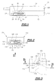
- the mobile telephone 10 represented in figure 1 comprises a box 12 forming the outer casing of the mobile telephone.
- This box is formed for example by two half-shells 12A, 12B assembled together along a peripheral function line.
- the box On its front face the box exhibits a set of orifices forming the passage for the buttons of a keypad.
- the orifices for the passage of the buttons and the junction line formed between the two half-shells are the origin of leaks intrinsic to the box. These leaks place the inside of the box permanently in communication with the ambient environment.
- these intrinsic leaks are shown diagrammatically by a single aperture 14 made artificially on the bottom of the box.
- the mobile telephone 10 comprises an electro-acoustic transducer 16 disposed inside the box 12.
- the electro-acoustic transducer 16 comprises in particular a first part 16A consisting of a basket and a second part 16B consisting of a diaphragm. This diaphragm is turned towards the front wall of the box 12.
- the electro-acoustic transducer 16 consists for example of a loudspeaker. It is adapted for the sound reproduction of music or speech signals received by the mobile telephone.
- the electro-acoustic transducer 16 is disposed inside an essentially sealed enclosure 18. This enclosure is disposed completely inside the box 12.
- the enclosure 18 is partially delimited by a wall 20 common to the box 12 and to the enclosure 18.
- the enclosure and the second part of the electro-acoustic transducer are disposed away from the front wall of the box.
- the corresponding enclosure can then envelope only the first part of the electro-acoustic transducer.
- the enclosure 18 is delimited by an inner wall 22 specific to the enclosure.
- the inner wall 22 lies completely inside the box 12 and is separate from the outer walls of the box.
- At least a part of several walls of the enclosure is common with a part of several walls of the box.
- the enclosure 18 delimits a rear volume 24 in contact with the opposite surface from the active emission surface of the loudspeaker constituting the transducer 16.
- the box 12 delimits a bearing zone 25 for supporting an ear of a user.
- the bearing zone 25 is formed partially by the wall 20 common to the box 12 and to the enclosure 18.
- the bearing zone 25 is furthermore formed by a front wall part specific to the box.
- An exit aperture 26 of the electro-acoustic transducer 16 passes through the bearing zone 25 supporting the ear of the user.
- This exit aperture 26 is formed through the wall 20 facing the active emission surface of the transducer, that is to say facing the active surface of the diaphragm of the loudspeaker in the example given.
- the second part of the electro-acoustic transducer is situated facing the exit aperture specific to the box.
- an exit aperture is provided within the frontal wall of the enclosure at the level of the rear region of the second part of the electro-acoustic transducer.
- the exit aperture specific to the enclosure is a hole exhibiting a surface area corresponding to the surface area required for the passage of the second part of the electro-acoustic transducer.
- the enclosure comprises an exit aperture provided on its frontal wall, at the level of the second part of the electro-acoustic transducer.
- the exit aperture cut in the enclosure exhibits a much smaller surface area than that of the corresponding exit aperture of the first aforesaid case.
- the enclosure is disposed away from the front wall of the box and only the second part of the transducer is designed in direct proximity to the front wall of the box facing the exit aperture provided within the box.
- the enclosure envelopes only the first part of the transducer.
- the exit aperture 26 consists for example of a single circular orifice whose diameter is substantially equal to 1 mm. This orifice is covered by a trellis forming an acoustic fabric. This trellis is 51% open. Thus, the effective surface area of the exit aperture 26, that is to say the free surface area allowing the actual passage of sound is substantially equal to 0.4 mm 2 .
- the enclosure 18 forms a resonant enclosure ensuring a function of filtering the sound message emitted. Accordingly, an interference aperture 28 is made through the bearing zone 25 supporting the ear of the user. This interference aperture 28 ensures that the inside of the enclosure 18 is placed in communication with the inside of the auditory pinna of the ear when the telephone is held right up against the ear of a user.
- the interference aperture 28 is formed for example of a single circular orifice.
- the diameter of this orifice is preferably between 0.5 and 2 mm and is advantageously substantially equal to 1 mm.
- This interference aperture is covered by a trellis forming an acoustic fabric, masking 51% of the interference aperture 28.
- the effective surface area of the interference aperture is between 0.1 mm 2 and 1.6 mm 2 approximately. It is preferably approximately 0.4 mm 2 .
- the effective surface areas of the interference aperture 28 and of the exit aperture 26 are substantially identical.
- a leakage aperture 30 passing through the inner wall 22 of the enclosure 18 is a leakage aperture 30 ensuring that the inside of the enclosure 18 is placed permanently in communication with the outside of the enclosure 18 by passing through a zone separate from the bearing zone 25 supporting the ear of the user. Stated otherwise, this leakage aperture 30 enables the inside of the rear volume of the enclosure 18 to be made to communicate with the ambient environment outside the pinna zone of the ear of the user.
- the leakage aperture 30 is for example aligned with the interference aperture 28. They are then formed in the opposite walls of the enclosure 18.
- At least one of the rear wall (with respect to the electroacoustic transducer) and of a lateral wall of the enclosure is common with a part of the rear or lateral wall of the box.
- the leakage aperture is provided on a part of the rear or lateral wall of the box (also constituting a wall of the enclosure).
- the leakage aperture 30 is for example formed of a single circular orifice whose diameter is substantially equal to 1.1 mm. This orifice is devoid of trellis partially masking it. Thus, its effective surface area is substantially equal to 0.95 mm 2 .
- the leakage aperture 30 has a larger effective surface area than the effective surface area of the interference aperture 28.
- the ratio of the effective surface area of the leakage aperture 30 to the effective surface area of the interference aperture 28 is between 1 and 8 approximately. It is preferably substantially equal to 2.
- the enclosure 18 emerging only through the interference aperture and the leakage aperture 30 creates a resonant interference filter.
- This filter makes it possible to eliminate the two spikes normally encountered in the frequency response of the electro-acoustic transducer.
- the spikes correspond approximately to the frequencies 1.5 kHz and 3.5 kHz.
- the resonant filter thus created is a low-pass filter. While operating, only a part of the filtered rear wave emanating from the electro-acoustic transducer 16 is reinjected inside the pinna of the ear through the interference aperture 28. This reinjection is carried out as a function of the ratio defined by the effective surface area of the interference aperture 28 to the effective surface area of the leakage aperture 30.
- the interference aperture 28 and leakage aperture 30 are dimensioned such that the resonant frequency of the filter lies between the two frequencies corresponding to the spikes.
- the gain and the phase make it possible to reduce the overall acoustic pressure inside the ear for frequencies immediately below the resonant frequency. Likewise, they make it possible to increase the overall acoustic pressure for frequencies just above the resonant frequency.
- the first spike of the frequency response is attenuated and the second spike is increased.
- the box 12 moreover exhibits a decompression aperture 32 made through the bearing zone 25 supporting the ear.
- This decompression aperture 32 caters for the link between the outside of the enclosure 18 and the auditory pinna of the ear when the telephone is applied against the ear.
- the decompression aperture 32 emerges outside the enclosure 18, passing through the inside of the box 12.
- this decompression aperture 32 is to convert the flow rate of the air stream produced by the electro-acoustic transducer 16 into a variation in pressure applied to the eardrum without excessively compressing the ear of the user.
- the assembly formed by the electro-acoustic transducer 16 and by the decompression aperture 32 thus constitutes a pressure generator rather than a flow rate generator.
- the presence of the decompression aperture 32 makes it possible to eliminate the decreasing frequency response at a relatively strong level for the low frequencies and at a relatively weak level for the high frequencies.
- the reduction is 30dB between 300 Hz and 3 Khz for example.
- the decompression aperture 32 reduces the sensitivity to variations in contact leaks between the ear of the user and the bearing zone 25. Accordingly, the effective surface area of the decompression aperture 32 is much greater than the mean open surface area formed by the contact leaks between the ear and the bearing zone.
- the mean open surface area is taken for example to be equal to that defined in the standard ear of the 3.2 low leak type in the ITU standard (standing for International Telecommunication Union) P.57.
- the effective surface area of the decompression aperture 32 is four times the mean open surface area of the contact leaks.
- the decompression aperture 32 is formed for example by a single circular orifice whose diameter is substantially equal to 4 mm.
- the ratio of the effective surface area of the decompression aperture 32 to the effective surface area of the interference aperture 28 is greater than 16.
- each aperture that is to say normally the thickness of the walls in which the apertures are made is very important to the acoustic qualities of the sound restitution.
- this length of the apertures influences the resonant frequency of the filter and its quality factor.
- each aperture is extended by a tubular span increasing the total length of the aperture.
- a tubular span is adapted so that the total length of each aperture is between 1 mm and 2.5 mm.
- FIG. 2 and 3 Represented in Figures 2 and 3 is a variant embodiment of the mobile telephone of Figure 1.
- elements identical or similar to those of Figure 1 are designated by the same reference numbers to which 100 has been added.
- the telephone 100 comprises a box 112 inside which is provided an enclosure 118 containing an electro-acoustic transducer 116.
- the enclosure 118 opens through the bearing zone 125 supporting an ear via an interference aperture 128.
- a leakage aperture 130 caters for the link between the rear volume 124 delimited by the enclosure 118 and the inside of the box 112.
- the exit aperture 126 of the electro-acoustic transducer is made on a wall 140 specific to the enclosure 118, this wall not constituting an outer wall of the box 112.
- the wall 140 thus lies inside the box 112.
- the exit aperture 126 of the transducer emerges into an intermediate chamber 142 delimited between the wall 140 specific to the enclosure and an outer wall 144 of the box 112.
- the wall 144 is a part of the bearing zone 120 supporting the ear of the user.
- the intermediate chamber 142 is linked to the inside of the box 112 by a conduit 146 formed between the walls 140 and 144.
- the decompression orifice 132 Passing through the wall 144 is the decompression orifice 132, which opens into the intermediate chamber 142.
- the exit orifice 126 of the transducer is substantially aligned with the decompression orifice 132.
- the presence of the sealed enclosure linked, on the one hand, to the pinna of the ear by the interference orifice and, on the other hand, to the outside of the enclosure by the leakage orifice, this being in the presence of the decompression orifice linking the ear to the outside of the enclosure makes it possible to satisfy, without requiring prior processing of the electro-acoustic transducer excitation signal, the conditions imposed by the specifications 11.10 phase 2+ GSM (standing for Global System for Mobile) with the standard ear of 3.2 low leak type of the ITU P.57 standard mentioned earlier.
- each of the apertures can be formed by at least two disjoint orifices constituting several independent holes.
- the total effective surface area of the independent orifices is equal to the effective surface area envisaged for the corresponding aperture.
- the invention can be implemented for any type of electrical apparatus comprising an electro-acoustic transducer such as a mobile telephone or a portable electronic diary.
Landscapes
- Engineering & Computer Science (AREA)
- Signal Processing (AREA)
- Health & Medical Sciences (AREA)
- Otolaryngology (AREA)
- Physics & Mathematics (AREA)
- Acoustics & Sound (AREA)
- Telephone Set Structure (AREA)
- Details Of Audible-Bandwidth Transducers (AREA)
- Obtaining Desirable Characteristics In Audible-Bandwidth Transducers (AREA)
Applications Claiming Priority (2)
| Application Number | Priority Date | Filing Date | Title |
|---|---|---|---|
| FR0103264 | 2001-03-09 | ||
| FR0103264A FR2822012B1 (fr) | 2001-03-09 | 2001-03-09 | Appareil electrique a transducteur electro-acoustique |
Publications (1)
| Publication Number | Publication Date |
|---|---|
| EP1244331A1 true EP1244331A1 (de) | 2002-09-25 |
Family
ID=8860954
Family Applications (1)
| Application Number | Title | Priority Date | Filing Date |
|---|---|---|---|
| EP02290554A Withdrawn EP1244331A1 (de) | 2001-03-09 | 2002-03-06 | Elektrisches Gerät mit elektroakustischem Wandler |
Country Status (5)
| Country | Link |
|---|---|
| US (1) | US6668063B2 (de) |
| EP (1) | EP1244331A1 (de) |
| JP (1) | JP2002359893A (de) |
| CN (1) | CN1376009A (de) |
| FR (1) | FR2822012B1 (de) |
Cited By (2)
| Publication number | Priority date | Publication date | Assignee | Title |
|---|---|---|---|---|
| EP1564970A1 (de) * | 2004-02-12 | 2005-08-17 | Sony Ericsson Mobile Communications AB | Elektroakustischer Wandler für eine tragbare Kommunikationsvorrichtung |
| WO2005079045A1 (en) * | 2004-02-12 | 2005-08-25 | Sony Ericsson Mobile Communications Ab | Electro-acoustic transducer for a portable communication device |
Families Citing this family (7)
| Publication number | Priority date | Publication date | Assignee | Title |
|---|---|---|---|---|
| GB0213732D0 (en) * | 2002-06-14 | 2002-07-24 | Mitel Knowledge Corp | Audio earpiece for wideband telephone handsets |
| US7483543B2 (en) * | 2003-01-06 | 2009-01-27 | Motorola, Inc. | Stereo imaging manifold and method for use in a portable electronic device |
| US7505602B2 (en) * | 2003-02-28 | 2009-03-17 | Sony Ericsson Mobile Communications Ab | Mobile device with improved acoustic porting |
| US7260364B2 (en) * | 2003-05-30 | 2007-08-21 | Sony Ericsson Mobile Communications Ab | Reverse mounted micro-speaker assemblies and mobile terminals including the same |
| KR20080010625A (ko) * | 2006-07-27 | 2008-01-31 | 삼성전자주식회사 | 모바일 기기 |
| US7697281B2 (en) * | 2008-09-05 | 2010-04-13 | Apple Inc. | Handheld computing device |
| KR101585388B1 (ko) * | 2013-08-30 | 2016-01-13 | 닛토덴코 가부시키가이샤 | 방수 통음막과, 그것을 구비하는 방수 통음 부재, 전자 기기, 전자 기기용 케이스 및 방수 통음 구조체 |
Citations (3)
| Publication number | Priority date | Publication date | Assignee | Title |
|---|---|---|---|---|
| EP0909110A2 (de) * | 1997-10-06 | 1999-04-14 | Nokia Mobile Phones Ltd. | Verfahren und Anordnung zur Verbesserung der Lecktoleranz einer Hörmuschel |
| GB2337396A (en) * | 1998-05-14 | 1999-11-17 | Motorola Inc | Portable electronic device with a speaker assembly coupled with cavities and passages to improve frequency response |
| WO2000021330A1 (en) * | 1998-10-05 | 2000-04-13 | Kirk Acoustics A/S | An electroacoustic communications unit |
-
2001
- 2001-03-09 FR FR0103264A patent/FR2822012B1/fr not_active Expired - Fee Related
-
2002
- 2002-03-06 EP EP02290554A patent/EP1244331A1/de not_active Withdrawn
- 2002-03-07 US US10/091,404 patent/US6668063B2/en not_active Expired - Fee Related
- 2002-03-08 CN CN02108493.9A patent/CN1376009A/zh active Pending
- 2002-03-08 JP JP2002063909A patent/JP2002359893A/ja active Pending
Patent Citations (3)
| Publication number | Priority date | Publication date | Assignee | Title |
|---|---|---|---|---|
| EP0909110A2 (de) * | 1997-10-06 | 1999-04-14 | Nokia Mobile Phones Ltd. | Verfahren und Anordnung zur Verbesserung der Lecktoleranz einer Hörmuschel |
| GB2337396A (en) * | 1998-05-14 | 1999-11-17 | Motorola Inc | Portable electronic device with a speaker assembly coupled with cavities and passages to improve frequency response |
| WO2000021330A1 (en) * | 1998-10-05 | 2000-04-13 | Kirk Acoustics A/S | An electroacoustic communications unit |
Cited By (3)
| Publication number | Priority date | Publication date | Assignee | Title |
|---|---|---|---|---|
| EP1564970A1 (de) * | 2004-02-12 | 2005-08-17 | Sony Ericsson Mobile Communications AB | Elektroakustischer Wandler für eine tragbare Kommunikationsvorrichtung |
| WO2005079045A1 (en) * | 2004-02-12 | 2005-08-25 | Sony Ericsson Mobile Communications Ab | Electro-acoustic transducer for a portable communication device |
| US7529520B2 (en) | 2004-02-12 | 2009-05-05 | Sony Ericsson Mobile Communications Ab | Electro-acoustic transducer for a portable communication device |
Also Published As
| Publication number | Publication date |
|---|---|
| US20020126865A1 (en) | 2002-09-12 |
| CN1376009A (zh) | 2002-10-23 |
| US6668063B2 (en) | 2003-12-23 |
| FR2822012B1 (fr) | 2003-06-20 |
| FR2822012A1 (fr) | 2002-09-13 |
| JP2002359893A (ja) | 2002-12-13 |
Similar Documents
| Publication | Publication Date | Title |
|---|---|---|
| US6389145B2 (en) | Methods and apparatus for controlling the output of moving armature transducers | |
| KR100329134B1 (ko) | 스피커 조립체를 갖는 휴대용 전자 장치 | |
| US6144738A (en) | Telephone handset with enhanced handset/handsfree receiving and alerting audio quality | |
| US8300871B2 (en) | Earphone for wideband communication | |
| US6134336A (en) | Integrated speaker assembly of a portable electronic device | |
| US7068782B2 (en) | Communications devices with receiver earpieces and methods therefor | |
| US6064894A (en) | Portable radio telephone having improved speaker and housing assembly for handsfree and private operation | |
| JP2609822B2 (ja) | 送話器 | |
| US6058315A (en) | Speaker assembly for a radiotelephone | |
| JP3784572B2 (ja) | イヤホンモニタを備えることにより、スピーカからユーザに耳管に至るまでの音響特性のユーザ間の変動を低減した電話送受話器 | |
| US5491747A (en) | Noise-cancelling telephone handset | |
| JPH11187487A (ja) | 受話器口の漏れ耐性を改善する方法および装置 | |
| US6668063B2 (en) | Electrical apparatus with electro-acoustic transducer | |
| ATE320159T1 (de) | Elektroakustische kommunikationseinheit | |
| JPH0549142B2 (de) | ||
| EP1074168B1 (de) | Telefon mit mitteln zur niederfrequenzgangsverbesserung | |
| KR102312004B1 (ko) | 마이크 실장 이어폰 | |
| JP2769554B2 (ja) | イヤーセット型送受話器 | |
| US7139394B2 (en) | Leak-tolerant handsfree telephone | |
| JP2008141694A (ja) | スピーカー装置、およびそれを備えた携帯電話端末 | |
| JPH05268310A (ja) | イヤーセット型送受話器 | |
| JP4816338B2 (ja) | 音声通信装置及びその音声出力制御方法 | |
| US7529520B2 (en) | Electro-acoustic transducer for a portable communication device | |
| JPS59126355A (ja) | 拡声電話機の音響装置 | |
| JPS61139189A (ja) | ハンドセツト |
Legal Events
| Date | Code | Title | Description |
|---|---|---|---|
| PUAI | Public reference made under article 153(3) epc to a published international application that has entered the european phase |
Free format text: ORIGINAL CODE: 0009012 |
|
| 17P | Request for examination filed |
Effective date: 20020311 |
|
| AK | Designated contracting states |
Kind code of ref document: A1 Designated state(s): AT BE CH CY DE DK ES FI FR GB GR IE IT LI LU MC NL PT SE TR |
|
| AX | Request for extension of the european patent |
Free format text: AL;LT;LV;MK;RO;SI |
|
| AKX | Designation fees paid |
Designated state(s): DE FR GB |
|
| RAP1 | Party data changed (applicant data changed or rights of an application transferred) |
Owner name: MELCO MOBILE COMMUNICATIONS EUROPE (SA) |
|
| STAA | Information on the status of an ep patent application or granted ep patent |
Free format text: STATUS: THE APPLICATION HAS BEEN WITHDRAWN |
|
| 18W | Application withdrawn |
Effective date: 20040304 |