EP1245443A2 - Überwachungssystem der Umgebung eines Fahrzeuges - Google Patents
Überwachungssystem der Umgebung eines Fahrzeuges Download PDFInfo
- Publication number
- EP1245443A2 EP1245443A2 EP02007080A EP02007080A EP1245443A2 EP 1245443 A2 EP1245443 A2 EP 1245443A2 EP 02007080 A EP02007080 A EP 02007080A EP 02007080 A EP02007080 A EP 02007080A EP 1245443 A2 EP1245443 A2 EP 1245443A2
- Authority
- EP
- European Patent Office
- Prior art keywords
- vehicle
- calculating
- distance
- environment monitoring
- probability
- Prior art date
- Legal status (The legal status is an assumption and is not a legal conclusion. Google has not performed a legal analysis and makes no representation as to the accuracy of the status listed.)
- Granted
Links
Images


Classifications
-
- G—PHYSICS
- G01—MEASURING; TESTING
- G01S—RADIO DIRECTION-FINDING; RADIO NAVIGATION; DETERMINING DISTANCE OR VELOCITY BY USE OF RADIO WAVES; LOCATING OR PRESENCE-DETECTING BY USE OF THE REFLECTION OR RERADIATION OF RADIO WAVES; ANALOGOUS ARRANGEMENTS USING OTHER WAVES
- G01S11/00—Systems for determining distance or velocity not using reflection or reradiation
- G01S11/12—Systems for determining distance or velocity not using reflection or reradiation using electromagnetic waves other than radio waves
-
- G—PHYSICS
- G06—COMPUTING OR CALCULATING; COUNTING
- G06T—IMAGE DATA PROCESSING OR GENERATION, IN GENERAL
- G06T7/00—Image analysis
- G06T7/20—Analysis of motion
-
- G—PHYSICS
- G08—SIGNALLING
- G08G—TRAFFIC CONTROL SYSTEMS
- G08G1/00—Traffic control systems for road vehicles
- G08G1/16—Anti-collision systems
- G08G1/166—Anti-collision systems for active traffic, e.g. moving vehicles, pedestrians, bikes
-
- B—PERFORMING OPERATIONS; TRANSPORTING
- B60—VEHICLES IN GENERAL
- B60R—VEHICLES, VEHICLE FITTINGS, OR VEHICLE PARTS, NOT OTHERWISE PROVIDED FOR
- B60R21/00—Arrangements or fittings on vehicles for protecting or preventing injuries to occupants or pedestrians in case of accidents or other traffic risks
- B60R21/01—Electrical circuits for triggering passive safety arrangements, e.g. airbags, safety belt tighteners, in case of vehicle accidents or impending vehicle accidents
- B60R21/013—Electrical circuits for triggering passive safety arrangements, e.g. airbags, safety belt tighteners, in case of vehicle accidents or impending vehicle accidents including means for detecting collisions, impending collisions or roll-over
-
- B—PERFORMING OPERATIONS; TRANSPORTING
- B60—VEHICLES IN GENERAL
- B60W—CONJOINT CONTROL OF VEHICLE SUB-UNITS OF DIFFERENT TYPE OR DIFFERENT FUNCTION; CONTROL SYSTEMS SPECIALLY ADAPTED FOR HYBRID VEHICLES; ROAD VEHICLE DRIVE CONTROL SYSTEMS FOR PURPOSES NOT RELATED TO THE CONTROL OF A PARTICULAR SUB-UNIT
- B60W2554/00—Input parameters relating to objects
-
- B—PERFORMING OPERATIONS; TRANSPORTING
- B60—VEHICLES IN GENERAL
- B60W—CONJOINT CONTROL OF VEHICLE SUB-UNITS OF DIFFERENT TYPE OR DIFFERENT FUNCTION; CONTROL SYSTEMS SPECIALLY ADAPTED FOR HYBRID VEHICLES; ROAD VEHICLE DRIVE CONTROL SYSTEMS FOR PURPOSES NOT RELATED TO THE CONTROL OF A PARTICULAR SUB-UNIT
- B60W30/00—Purposes of road vehicle drive control systems not related to the control of a particular sub-unit, e.g. of systems using conjoint control of vehicle sub-units
- B60W30/08—Active safety systems predicting or avoiding probable or impending collision or attempting to minimise its consequences
- B60W30/09—Taking automatic action to avoid collision, e.g. braking and steering
Definitions
- the present invention relates to a vehicle environment monitoring system that monitors an external environment of a vehicle on which the system is installed.
- the system detects an external object, which may collide with the vehicle from an image obtained by an imaging device mounted on the vehicle.
- the system hereof assists a user in avoiding a potential collision against a large animal, such as a deer, a bear or the like, since such collision has an adverse influence on the vehicle.
- a warning device for giving a warning when the distance between the vehicle and an object approaching the vehicle becomes short was proposed by Japanese Laid-Open Patent Publication No. 2001-6096.
- the device detects a distance between the vehicle and the object based on the displacement between images of the object, that is, the parallax of images obtained by two cameras mounted on the vehicle.
- the change rate of the detected distance is calculated as a relative speed, and a time period TY until the estimated time the vehicle may collide with the object (an estimated allowance time period TY) is calculated based on the relative speed and the distance.
- a warning is given when the estimated allowance time period TY is shorter than a predetermined allowance time period T.
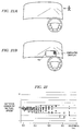
- FIG. 22 is a diagram showing actually detected data of an error of the relative speed detected by the method shown in the above publication.
- the error of the detected relative speed increases as the distance from the object increases. Therefore, calculating the estimated allowance time period TY based on the relative speed and the distance raises a problem that the warning may be given too early or too late.
- the above-described conventional method causes another problem that the vehicle running in the opposite lane and approaching at a comparatively high speed, or the vehicle running ahead in the same lane may be detected as an object with high possibility of collision, which often causes unnecessary warnings.
- the present invention provides a vehicle environment monitoring system, which detects an object existing in an external environment of the vehicle from an image, obtained by imaging means mounted on the automotive vehicle.
- the vehicle environment monitoring system includes vehicle speed detecting means, distance calculating means, relative speed calculating means, and probability determining means.
- the vehicle speed detecting means detects a running speed of the vehicle.
- the distance calculating means calculates a distance between the object and the vehicle, based on the image obtained by the imaging means.
- the relative speed calculating means calculates a relative speed between the object and the vehicle, according to the distance calculated by the distance calculating means.
- the probability determining means determines whether or not there is a substantial probability that the vehicle may collide with the object, based on the running speed of the vehicle and the distance calculated by the distance calculating means.
- a warning alarm is generated, provided on condition that the relative speed between the object and the vehicle is in the vicinity of the running speed of the vehicle.
- this vehicle environment monitoring system it is determined whether or not there is a significant probability that the vehicle may collide with the object, based on the running speed of the vehicle instead of the relative speed, and the distance between the vehicle and the object. This probability is determined on condition that the relative speed is in the vicinity of the running speed of the vehicle, in other word, the sensed object is moving at a relatively low speed, or standing still. Therefore, it is possible to issue a warning at a desired timing, even if the detection error of the relative speed is relatively large. Further, since the determination is carried out on condition that the relative speed is in the vicinity of the vehicle speed, it is possible to substantially prevent unnecessary warnings when the vehicle is approaching another vehicle that is running in the opposite lane, or running ahead in the same lane.
- the determining means carries out the determination, when an absolute value of a difference between the relative speed and the running speed of the vehicle is less than or equal to half of the running speed of the vehicle.
- the vehicle environment monitoring system further includes relative position-detecting means and movement vector-calculating means.
- the relative position-detecting means detects a relative position of the object to the vehicle, based on the image obtained by the imaging means and the distance calculated by the distance calculating means, to thereby obtain position data.
- the movement vector-calculating means calculates positions of the object in a real space, based on a plurality of time series items of the position data detected on the object by the relative position-detecting means, and calculates a movement vector of the object based on the positions in the real space.
- the probability determining means determines whether or not the probability of collision is high based on the movement vector, when it is determined based on the running speed of the vehicle and the distance that there is a possibility of collision.
- the movement vector-calculating means includes approximate straight line-calculating means for calculating an approximate straight line approximating a locus of relative movement of the object, and position data-correcting means for correcting the time series items of the position data by using the approximate straight line.
- the movement vector-calculating means calculates the movement vector based on the corrected time series items of the position data.
- the probability determining means carries out the determination by applying collision determination conditions that are dependent on a width of the vehicle.
- the imaging means comprises two infrared cameras capable of detecting infrared rays.
- an animal, a running automotive vehicle, or the like can easily be detected, even when the driver is driving at night and it is difficult to recognize them.
- the imaging means comprises two TV cameras for detecting infrared rays or visible rays
- the relative position-detecting means includes search area-setting means and corresponding object image-identifying means.
- the search area-setting means sets, based on a position of an object image contained in an image output from one of the two TV cameras, a search area within an image output from the other of the two TV cameras, for searching for a corresponding object image contained in the image output from the other TV camera.
- the corresponding object image-identifying means identifies the corresponding object image by carrying out a correlation operation on data within the search area.
- the distance-calculating means calculates the distance between the vehicle and the object, based on a parallax between the first object image and the corresponding object image.
- the vehicle environment monitoring system includes warning means for warning a driver, when it is determined by the determining means that there is a high probability of collision against the object.
- the warning means is preferably inhibited from warning the driver when the driver is carrying out a braking operation, and at the same time, deceleration caused by the braking operation is larger than a predetermined threshold.
- the driver is not warned when he has already recognized the object and is carrying out an appropriate braking operation. This makes it possible to substantially prevent the driver from being annoyed by an unnecessary warning.
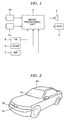
- FIG. 1 is a block diagram showing the arrangement of a vehicle external environment monitoring system according to an illustrative embodiment of the invention
- FIG. 2 is a diagram illustrating portions of a vehicle at which mounting cameras appearing in FIG. 1 are mounted;
- FIG. 3 is a flowchart showing a procedure of processing steps executed by an image-processing unit appearing in FIG. 1;
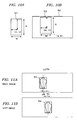
- FIGS. 5A and 5B are diagrams each showing halftone portions as hatched areas, which are useful in explaining gray scale images obtained by infrared cameras, in which:
- FIG. 5A shows a right image obtained by a right one of the infrared cameras
- FIG. 5B shows a left image obtained by a left one of the same
- FIG. 6 is a diagram showing a black area as a hatched one, which is useful in explaining an image formed by binarization of a gray scale image
- FIGS. 7A to 7C are diagrams which are useful in explaining a process for converting binarized image data to run length data and labeling of objects for identification thereof;
- FIGS. 8A and 8B are diagrams useful in explaining how objects are tracked at time intervals
- FIG. 9A is a diagram useful in explaining a target image in the right image.
- FIG. 9B is a diagram useful in explaining a search area set in the left image
- FIG. 10A and 10B are diagrams useful in explaining a correlation operation carried out on data within the search area
- FIGS. 11A and 11B are diagrams useful in explaining a method of calculating a parallax
- FIG. 12 is a diagram useful in explaining a method of calculating a distance between the vehicle and the object based on the parallax;
- FIGS. 13A and 13B are diagrams useful for explaining a coordinate system used in the present embodiment
- FIG. 15 is a diagram showing the displacement of the object in the images due to turning of the vehicle.
- FIG. 16 is a diagram useful in explaining a method of calculating a relative movement vector
- FIG. 17 is a diagram useful in explaining conditions for determining whether or not a warning should be issued.
- FIG. 18 is a diagram useful in explaining divisional areas in front of the vehicle.
- FIG. 19 is a diagram useful in explaining a case in which a collision is liable to occur.
- FIG. 20 is a diagram useful in explaining a method of incoming object collision determination dependent on a width of the vehicle
- FIG. 21A shows a state where a screen of a head up display is not displayed
- FIG. 21B shows a state where a screen of the head up display is displayed.
- FIG. 1 there is shown the arrangement of a vehicle environment monitoring system, according to an illustrative embodiment of the invention.
- the system depicted in FIG. 1 includes right and left infrared cameras 1R, 1L capable of detecting far-infrared rays, a yaw rate sensor 5 for detecting yaw rate of the vehicle, a vehicle speed sensor 6 for detecting traveling speed (vehicle speed) VCAR of the vehicle, a brake sensor 7 for detecting an operation amount of a brake (not shown), and an image-processing unit 2 for detecting an object, such as an animal or the like, ahead of the vehicle. Objects are detected based on image data obtained by the above cameras 1R, 1L.
- the system also includes a speaker 3 for generating a voice alarm for warning the driver, and a head up display (hereinafter referred to as the "HUD") 4 for displaying an image obtained by the camera 1R or 1L.
- the HUD 4 permits the driver to recognize the object having the high probability of collision against the vehicle.
- the cameras 1R, 1L are arranged in a front portion of the automotive vehicle 10 at locations symmetric with respect to the longitudinal central axis of the vehicle 10.
- the cameras are rigidly fixed to the vehicle such that the two cameras 1R, 1L have optical axes in parallel with each other and disposed at equal heights from a road surface.
- the infrared cameras 1R, 1L have a characteristic that the output signal level thereof becomes higher (the luminance of an image of an object increases) as the temperature of the object becomes higher.
- the image-processing unit 2 includes an A/D converter circuit for converting input analog signals to digital signals, an image memory for storing digitized image signals, a CPU (Central Processing Unit) for carrying out arithmetic operations, a RAM (Random Access Memory) used by the CPU for storing data being processed in the arithmetic operations, a ROM (Read Only Memory) storing programs executed by the CPU, tables, and maps, and an output circuit for outputting driving signals to the speaker 3, display signals to the HUD 4, and the like.
- Output signals from the cameras 1R, 1L and the sensors 5 to 7 are converted to digital signals and input to the CPU.
- the HUD 4 is arranged such that a screen 4a thereof is displayed in a front window at a location ahead of the driver.
- FIG. 3 is a flowchart showing a procedure of processing steps executed by the image-processing unit 2.
- output signals from the cameras 1R, 1L are subjected to A/D conversion by the A/D converter circuit and the resulting digital data are stored in the image memory (steps S11, S12, S13).
- Data of images stored in the image memory is data of gray scale images including luminance information.
- FIGS. 5A and 5B are diagrams for explaining gray scale images obtained by the respective cameras 1R, 1L (a right image by the camera 1R, and a left image by the camera 1L). Hatched areas in the right and left images are halftone (gray) areas, while areas surrounded by thick solid lines are areas at a high luminance level (at a high temperature).
- the areas surrounded by thick, solid lines are areas (hereinafter referred to as "high luminance areas") of detected objects, displayed in white on the screen.
- high luminance areas areas of detected objects, displayed in white on the screen.
- an identical object is displayed as dual, respective images at respective locations horizontally displaced from each other, so that it is possible to calculate a distance from the vehicle 10 to the object, based on the image displacement (parallax).
- the right image is set to a reference image
- the digital image data representative of the reference image is binarized (converted to 1-bit data) such that an area at a level of luminance equal to or higher than a luminance threshold ITH, experimentally determined, is set to "1" (white) and an area at a lower level of luminance than the threshold ITH is set to "0" (black).
- FIG. 6 shows an image obtained by binarization of the FIG. 5A image. In the figure, a hatched area represents a black area, while areas surrounded by thick solid lines (high luminance areas) represent respective white areas.
- FIG. 7A is a diagram for explaining the encoding process.
- areas set to white by the above binarization are represented by lines L1 to L8 indicative of respective lines of pixels.
- the lines L1 to L8 each have a width of one pixel in the y direction, and are actually arranged side by side without any gaps in the y direction, they are shown as separate lines spaced from each other for clarity of description.
- the lines L1 to L8 have respective lengths of two pixels, two pixels, three pixels, eight pixels, seven pixels, eight pixels, eight pixels, and eight pixels in the x direction.
- the run length data represents each of the lines L1 to L8 by the coordinates of the starting point (point of the left end) of the line and the length (the number of pixels) of the line from the starting point to the ending point (point of the right end) of the same.
- the line L3 is formed of three pixels (x3, y5), (x4, y5) and (x5, y5), and represented by the run length data (x3, y5, 3).
- an object is extracted by labeling the same, as shown in FIG. 7B. That is, out of the lines L1 to L8 encoded into the run length data, the lines L1 to L3 overlapping in the y direction are regarded as one object 1, and the lines L4 to L8 overlapping in the y direction are regarded as one object 2, whereby object labels 1 and 2 are added to the run length data.
- This processing enables, e.g, the high luminance areas appearing in FIG. 6, to be grasped as objects 1 to 4, respectively.
- the centroid G of an extracted object (image of an object), the area S of the extracted object, and the aspect ratio ASPECT of a rectangle circumscribing the extracted object (indicated in FIG. 7C by broken lines) are calculated.
- the area S is calculated by integrating the lengths of the run length data of an identical object.
- the coordinates of the centroid G is calculated as the x coordinate of a line equally dividing the area S along the y direction into halves, and the y coordinate of a line equally dividing the area S along the x direction into halves.
- the aspect ratio ASPECT is calculated as Dy/Dx which is a ratio of Dy to Dx appearing in FIG. 7C. It should be noted that the position of the centroid of the circumscribing rectangle may be used in place of that of the centroid G of the extracted object.
- objects are tracked at time intervals, that is, identification or recognition of identical objects is carried out whenever each sampling repetition period elapses.
- a time obtained by discretizing time t as an analog amount by a sampling repetition period is represented by k
- objects 1 and 2 extracted at time k, as shown in FIG. 8A, and objects 3 and 4 extracted at time (k + 1) as shown in FIG. 8A are checked as to their identity. More specifically, it is determined that the objects 3 and 4 are identical with the respective objects 1 and 2 when the following identification conditions (1) to (3) are satisfied, and the objects 3 and 4 are labeled as objects 1 and 2 to thereby track the objects at time intervals:
- each object When comparison is made between FIG. 8A and FIG. 8B, the size of each object is increased in FIG. 8B, but the objects 1 and 3 satisfy the above identification conditions, and the objects 2 and 4 satisfy the above identification conditions. Hence, the objects 3 and 4 can be identified with the respective objects 1 and 2.
- the position coordinates (of the centroid) of each object thus identified are stored in the memory as time series items of position data, and used for carrying out subsequent arithmetic operations.
- step S20 in FIG. 3 the vehicle speed VCAR detected by the vehicle speed sensor 6 and the yaw rate YR detected by the yaw rate sensor 5 are read in for integration of the yaw rate YR over time, whereby the angle ⁇ r of turn of the automotive vehicle 10 (see FIG. 14) is calculated.
- steps S31 to S33 an operation for calculating a distance z between the object and the automotive vehicle 10 is carried out in parallel with the processes at steps S19 and 20.
- This arithmetic operation takes a longer time period than the processes at steps S19 and 20, and hence it is executed at a longer repetition period than that of the processes at steps S 19 and 20 (approximately three times as long as a repetition period of execution of the processes from step S11 to step S20).
- step S31 one of objects tracked by using the binarized image of the reference image (right image) is selected, whereby as shown in FIG. 9A, a target image R1 (whole area surrounded by a circumscribing rectangle is set to a target image in this example) is extracted from the right image.
- a search area for searching an image hereinafter referred to as the "corresponding image"
- the corresponding image is set within the left image, and the corresponding image is extracted by performing a correlation operation. More specifically, as shown in FIG.
- a search area R2 is set in the left image based on the coordinates of each vertex of the target image R1, and the total sum value C (a, b) of luminance differences indicative of a degree of correlation with the target image R1 is calculated as to data within the search area R2 by using the following equation (1), whereby an area which provides the minimum value of the total sum value C (a, b) is extracted as the corresponding image.
- the correlation operation is carried out not by using data of binarized images (binary data) but by using data of gray scale images (gray scale data).
- an area R2a (shown by broken lines in FIG. 9B) narrower than the search area R2 is set to the search area based on the position data.
- IR (m, n) represents a luminance value of a position shown by coordinates (m, n) in the target image R1 appearing in FIG.
- IL(a + m - M, b + n - N) represents a luminance value of a position shown by coordinates (m, n) in a local area R3 having the same shape as that of the target image R1 with a reference point (origin of its own coordinate system) set to coordinate (a, b) in the search area R2 as indicated in FIG. 10B.
- a position minimizing the total sum value C (a, b) of the luminance differences is obtained by changing the coordinates (a, b) of the reference point, whereby the position of the corresponding image can be determined.
- a distance dR (the number of pixels) between the centroid of the target image R1 and a center line LCTR of the right image
- a distance dL (the number of pixels) between the centroid of the corresponding image R4 and a center line LCTR of the left image
- B designates the length of a baseline, that is, a horizontal distance (in the x direction) between the center position of an imaging element 11R of the camera 1R and the center position of an imaging element 11L of the camera 1L (i.e. distance between the optical axes of the respective cameras), as shown in FIG. 12;
- F designates the focal distance of lenses 12R, 12L;
- p designates a space interval between pixels in the imaging elements 11R, 11L;
- coordinates (x, y) in the image and the distance z calculated by using the equation (2) are applied to the following equations (3) for conversion to real space coordinates (X, Y, Z).
- the coordinate system of the real space coordinates (X, Y, Z) (real space coordinate system) is defined as shown in FIG. 13A with the position of a mid point (position fixed on the automotive vehicle 10) of mounting positions at which the cameras 1R, 1L are mounted being set to an origin O of the real space coordinate system, and coordinates in a coordinate system of an image (imaginary image, referred to hereinafter) corresponding to the real coordinate system is defined as shown in FIG. 13B, with the center of the image being set to the origin of the coordinate system corresponding to the real space coordinate system, the horizontal direction being defined as the x direction, and the vertical direction being defined as the y direction.
- (xc, yc) are obtained by converting the coordinates (x, y) in the coordinate system of the right image to coordinates in the coordinate system of the imaginary image, the center of which is caused to coincide with the origin O of the real space coordinate system, based on the relative relationship of the mounting position of the camera 1R and the origin O of the real space coordinate system.
- f represents a ratio between the focal distance F and the pixel-to-pixel space interval p.
- the real space coordinates (X, Y, Z) are applied to the following equation (4) to calculate corrected coordinates (Xr, Yr, Zr).
- Real space position data (Xr, Yr, Zr) thus calculated is stored in the memory in a manner correlated to each corresponding object.
- the corrected coordinates are denoted as coordinates (X, Y, Z).
- an approximate straight line LMV corresponding to a relative movement vector between an identical object and the automotive vehicle 10 is obtained based on N real space position data items, i.e. time series position data (N is a number equal to or close to 10, for instance) after the turn angle-dependent correction, which were obtained during a time period ⁇ T.
- N is a number equal to or close to 10, for instance
- FIG. 16 is a diagram illustrating the approximate straight line LMV.
- P(0), P(1), P(2), across, P(N - 2), P(N - 1) designate points indicated by respective time series position data items (data points) after the turn angle-dependent correction.
- a numeric value in parentheses added to each P indicating the coordinates of each data point (position coordinates) shows that the larger the numeric value is, the older the data item having the numeric value is.
- P(0) indicates the latest position coordinates
- P(1) indicates position coordinates obtained one sampling repetition period earlier
- P(2) indicates position coordinates obtained two sampling repetition periods earlier.
- s 1x • DX(j) + 1y • DY(j) + 1z • DZ(j)
- a variance-covariance matrix V of the coordinates at the respective data points is represented by the following equation (7). Since a characteristic value ⁇ for this variance-covariance matrix V corresponds to the variance of the inner products s, a characteristic vector corresponding to the largest one of three characteristic values calculated from the matrix becomes the direction vector L desired to be obtained. It should be noted that in order to calculate characteristic values and a characteristic vector from the matrix of the equation (7), a method known as Jacobian method (described e.g. in "Suuchi-Keisan Handbook (Handbook of Numeral Calculus)" (published by Ohmsha, Ltd, Tokyo, Japan)) is used.
- the aforementioned relative movement vector can be obtained.
- an approximate straight line approximating the locus of relative movement of an object to the automotive vehicle 10 is calculated, based on a plurality of (N) data items of position data during a monitoring time period ⁇ T, and a relative movement vector is determined, based on the approximate straight line. This makes it possible to reduce adverse influence of position detection errors, and more accurately estimate the probability of collision against the object in advance.
- a warning determination process (FIG. 4) is carried out by determining whether or not there is a possibility of collision against the detected object, and issuing a warning if the probability of the collision is high.
- Zv(0) represents the latest detected distance value (although v is added to the symbol to indicate that the symbol represents a value of a data item corrected by using the approximate straight line LMV, the Z coordinate itself has the same value as it has before the correction), and Zv(N - 1) represents a distance value detected a time period ⁇ T earlier.
- T represents a lead time provided so as to enable determining the possibility of collision a time period T earlier than an estimated collision time.
- T is set to a time period within a range of e.g. two to five seconds.
- H represents a predetermined height for defining a range in the Y direction, that is, in the direction of height, which is set to e.g. a height approximately two times as large as that of the automotive vehicle 10.
- the expression (10a) is satisfied when the relative speed Vs is in the vicinity of the vehicle speed VCAR, in other words, when the sensed object is moving at a relatively low speed, or standing still.
- a significant probability of collision is determined on condition that the expressions (10a) and (10b) are satisfied, and the warning is issued according to the position and the relative movement vector of the object. Therefore, even if a detection error of the relative speed is comparatively large, the probability of collision is accurately determined, and the warning can be issued at a desired timing. Further, other vehicles that are running in the opposite lane, or running ahead in the same lane, are excluded from the objects of warning, by the condition of the expression (10a). Accordingly, frequent unnecessary warnings can be substantially prevented.
- an area which can be monitored by the cameras 1R, 1L is shown by an area AR0 defined by an outer triangle indicated by thick solid lines.
- the area AR1 is an area corresponding to a range including the width ⁇ of the automotive vehicle 10 and allowances ⁇ , ⁇ (each having a value of e.g. 50 to °100 cm) provided on opposite sides of the vehicle 10, in other words, an area having a width of ( ⁇ /2 + ⁇ ) on each side of the central axis in the longitudinal direction of the vehicle 10.
- the areas AR2, AR3 are areas having X coordinates with larger absolute values than those of X coordinates in the closing object determination area (areas laterally outward of the closing object determination area). An object in one of these areas AR2 and AR3 is subjected to an incoming object collision determination process described hereinafter, for determining the possibility of potential collision of an incoming object. These areas AR2 and AR3 are referred to as the "incoming object determination areas”. Further, the above areas have the predetermined height H in the Y direction, as shown in the expression (11).
- step S41 becomes affirmative (Yes) when the object exists in the closing object determination area AR1 or in one of the incoming object determination areas AR2, AR3.
- step S42 it is determined whether or not the object exists in the closing object determination area AR1. If the answer to the question of step S42 is affirmative (Yes), the program immediately proceeds to step S44, whereas if the answer is negative (No), the incoming object collision determination process for determining the possibility of potential collision of the incoming object is carried out at step S43. More specifically, it is determined whether or not the following expression (12) is satisfied by the difference between the latest x coordinate xc(0) (as described above, c is added to the symbol to indicate that the symbol represents the x coordinate corrected by causing the center position of the image to coincide with the origin O of the real space coordinate system) and an x coordinate xc(N - 1) obtained a time period ⁇ T earlier. If the following expression (12) is satisfied, it is determined that there is a high probability of collision.
- step 43 when it is determined at step 43 that there is a high probability of collision, the program proceeds to step S44, whereas when it is determined that there is not a high probability of collision, the warning determination process is terminated.
- a warning output determination process is carried out, for determining whether or not a warning should be issued.
- the program immediately proceeds to step S45 to issue a warning.
- deceleration Gs generated by the braking operation is calculated (as a positive value).
- GTH a predetermined threshold
- the program proceeds to step S45, whereas when Gs > GTH holds, it is determined that collision can be avoided by the braking operation, followed by terminating the warning determination process. This makes it possible to substantially prevent the driver from being warned when he is carrying out an appropriate braking operation, thereby preventing the driver from being annoyed by unnecessary warnings.
- the threshold thus determined corresponds to a condition for stopping the vehicle 10 at a distance of travel equal to or smaller than the distance Zv(0), assuming that the deceleration Gs generated by the braking operation is maintained.
- a voice alarm is generated by the speaker 3, and as shown in FIG. 21B, an image obtained e.g. by the camera 1R is displayed on the screen 4a of the HUD 4 such that a closing object is emphatically displayed (for instance, enclosed in a frame for emphasis).
- FIG. 21A shows a state where the screen 4a is not displayed, while FIG. 21B shows a state where the screen 4a is displayed. This enables the driver to positively recognize an object having a high probability of collision against the vehicle 10.
- the probability of collision is determined on condition that the expressions (10a) and (10b) are satisfied, and the warning is issued according to the position and the relative movement vector of the object. Therefore, even if a detection error of the relative speed is comparatively large, the probability of collision is accurately determined, and the warning can be issued at a desired timing. Further, other vehicles that are running in the opposite lane or running ahead in the same lane are excluded from the objects of warning, by the condition of the expression (10a). Accordingly, frequent unnecessary warnings can be substantially prevented.
- positions of an identical object in the real space are calculated based on a plurality of time series items of position data of the object, and the movement vector of the object is obtained based on its positions in the real space. Then, the probability of collision between the object and the automotive vehicle 10 is determined based on the movement vector thus calculated. Therefore, using the system hereof, differently from the conventional system, it is possible to substantially prevent the occurrence of an erroneous determination, and thereby enhance accuracy of determination of the probability of collision.
- the approximate straight line LMV approximating the locus of relative movement of an object to the automotive vehicle 10 is calculated, and the position coordinates of the object are corrected such that positions of the detected object are on the approximate straight line, and the movement vector of the object is obtained based on the corrected position coordinates.
- the image-processing unit 2 constitutes distance calculating means, relative speed calculating means, relative position-detecting means, movement vector-calculating means, determining means, and part of warning means. More specifically, steps S31 to S33 in FIG. 3 correspond to the distance calculating means. The calculation of the equation (9) corresponds to the relative speed calculating means. Steps S14 to S19 in FIG. 3 correspond to the relative position-detecting means. Steps S20 to S23 in the figure correspond to the movement vector-calculating means. Step S41 to S44 in FIG. 4 correspond to the determining means. Step S45 in FIG. 4 and the speaker 3 and the HUD 4 correspond to the warning means.
- the image-processing unit 2 constitutes a distance calculating module, a relative speed calculating module, a relative position-detecting module, a movement vector-calculating module, a probability determining module, and part of a warning module. More specifically, steps S31 to S33 in FIG. 3 correspond to the distance calculating module. The calculation of the equation (9) corresponds to the relative speed calculating module. Steps S14 to S19 in FIG. 3 correspond to the relative position-detecting module. Steps S20 to S23 in the figure correspond to the movement vector-calculating module. Step S41 to S44 in FIG. 4 correspond to the probability determining module. Step S45 in FIG. 4 and the speaker 3 and the HUD 4 correspond to the warning module.
- infrared cameras are used as imaging means, this is not limitative, but TV cameras capable of detecting only normal visible rays, as disclosed in Japanese Laid-Open Patent Publication (Kokai) No. 9-226490, may be employed.
- infrared cameras By using infrared cameras, however, the extraction process for extracting an animal or a running vehicle can be simplified, and the system can be realized by using an arithmetic unit having relatively low performance.
- a vehicle environment monitoring system for an automotive vehicle is capable of accurately detecting the movement of an object existing in an external environment of the vehicle, and determining the probability of collision between the object and the vehicle, thereby appropriately warning the driver.
- a running speed of the vehicle is detected, and a distance between the object and the vehicle is calculated, based on the image obtained by the imaging device.
- a relative speed between the object and the vehicle is calculated according to the calculated distance. It is determined whether or not there is a significant probability that the vehicle may collide with the object, based on the running speed of the vehicle and the distance therebetween on condition that the relative speed is in the vicinity of the running speed of the vehicle.
Landscapes
- Physics & Mathematics (AREA)
- Engineering & Computer Science (AREA)
- General Physics & Mathematics (AREA)
- Electromagnetism (AREA)
- Radar, Positioning & Navigation (AREA)
- Remote Sensing (AREA)
- Multimedia (AREA)
- Computer Vision & Pattern Recognition (AREA)
- Theoretical Computer Science (AREA)
- Traffic Control Systems (AREA)
- Image Processing (AREA)
- Image Analysis (AREA)
Applications Claiming Priority (2)
| Application Number | Priority Date | Filing Date | Title |
|---|---|---|---|
| JP2001099285 | 2001-03-30 | ||
| JP2001099285A JP4615139B2 (ja) | 2001-03-30 | 2001-03-30 | 車両の周辺監視装置 |
Publications (3)
| Publication Number | Publication Date |
|---|---|
| EP1245443A2 true EP1245443A2 (de) | 2002-10-02 |
| EP1245443A3 EP1245443A3 (de) | 2009-08-19 |
| EP1245443B1 EP1245443B1 (de) | 2010-09-22 |
Family
ID=18952840
Family Applications (1)
| Application Number | Title | Priority Date | Filing Date |
|---|---|---|---|
| EP02007080A Expired - Lifetime EP1245443B1 (de) | 2001-03-30 | 2002-03-27 | Überwachungssystem der Umgebung eines Fahrzeuges |
Country Status (4)
| Country | Link |
|---|---|
| US (1) | US6789015B2 (de) |
| EP (1) | EP1245443B1 (de) |
| JP (1) | JP4615139B2 (de) |
| DE (1) | DE60237739D1 (de) |
Cited By (27)
| Publication number | Priority date | Publication date | Assignee | Title |
|---|---|---|---|---|
| WO2004034782A1 (en) * | 2002-10-15 | 2004-04-29 | C. R. F. Societa Consortile Per Azioni | System to avoid the collision of a vehicle with animals |
| FR2850196A1 (fr) * | 2003-01-21 | 2004-07-23 | Bosch Gmbh Robert | Procede de mise en oeuvre d'un vehicule automobile |
| WO2005029439A1 (de) * | 2003-09-11 | 2005-03-31 | Daimlerchrysler Ag | Verfahren und vorrichtung zur ermittlung einer position eines kraftzfahrzeuges auf einer strasse |
| EP1469442A3 (de) * | 2003-04-17 | 2005-04-13 | Fuji Jukogyo Kabushiki Kaisha | Fahrassistenzsystem für Fahrzeuge |
| WO2005038393A1 (de) * | 2003-09-19 | 2005-04-28 | Daimlerchrysler Ag | Entfernungsbestimmung eines objekts |
| DE102004057296A1 (de) * | 2004-11-26 | 2006-06-08 | Daimlerchrysler Ag | Lane-Departure-Warning mit Unterscheidung zwischen Fahrbahnrandmarkierung und baulicher Begrenzung des Fahrbahnrandes |
| EP1475764A3 (de) * | 2003-05-02 | 2006-06-21 | IBEO Automobile Sensor GmbH | Verfahren und Vorrichtung zur Ermittlung der Wahrscheinlichkeit für eine Kollision eines Fahrzeugs mit einem Gegenstand |
| EP1496486A3 (de) * | 2003-06-20 | 2008-01-23 | Fuji Jukogyo Kabushiki Kaisha | Fahrassistenzgerät für Fahrzeuge |
| EP1772840A3 (de) * | 2005-10-06 | 2008-03-26 | Fuji Jukogyo Kabushiki Kaisha | Kollisionsbestimmung und Vorrichtung zur Steuerung des Fahrzeugverhaltens |
| US7388476B2 (en) | 2004-11-30 | 2008-06-17 | Honda Motor Co., Ltd. | Vehicle surroundings monitoring apparatus |
| US7489805B2 (en) | 2004-11-30 | 2009-02-10 | Honda Motor Co., Ltd. | Vehicle surroundings monitoring apparatus |
| US7515737B2 (en) | 2004-11-30 | 2009-04-07 | Honda Motor Co., Ltd. | Vehicle surroundings monitoring apparatus |
| US7526104B2 (en) | 2004-11-30 | 2009-04-28 | Honda Motor Co., Ltd. | Vehicle surroundings monitoring apparatus |
| US7545955B2 (en) | 2004-11-30 | 2009-06-09 | Honda Motor Co., Ltd. | Vehicle surroundings monitoring apparatus |
| US7561719B2 (en) | 2004-11-30 | 2009-07-14 | Honda Motor Co., Ltd. | Vehicle surroundings monitoring apparatus |
| US7567688B2 (en) | 2004-11-30 | 2009-07-28 | Honda Motor Co., Ltd. | Apparatus for and method of extracting image |
| FR2927720A1 (fr) * | 2008-02-19 | 2009-08-21 | Peugeot Citroen Automobiles Sa | Dispositif et procede d'aide au franchissement d'une intersection pour un vehicule automobile. |
| US7590263B2 (en) | 2004-11-30 | 2009-09-15 | Honda Motor Co., Ltd. | Vehicle vicinity monitoring apparatus |
| US7599521B2 (en) | 2004-11-30 | 2009-10-06 | Honda Motor Co., Ltd. | Vehicle vicinity monitoring apparatus |
| US7616806B2 (en) | 2004-11-30 | 2009-11-10 | Honda Motor Co., Ltd. | Position detecting apparatus and method of correcting data therein |
| US7620237B2 (en) | 2004-11-30 | 2009-11-17 | Honda Motor Co., Ltd. | Position detecting apparatus and method of correcting data therein |
| CN101727759A (zh) * | 2008-10-14 | 2010-06-09 | 罗伯特·博世有限公司 | 用于汽车的驾驶员辅助系统 |
| FR2942193A1 (fr) * | 2009-02-13 | 2010-08-20 | Peugeot Citroen Automobiles Sa | Dispositif et procede de securisation de la conduite d'un vehicule a moteur en presence d'un risque de collison avec un obstacle mobile, et dispositif d'aide associe |
| DE102005056429B4 (de) * | 2004-11-30 | 2010-09-30 | Honda Motor Co., Ltd. | Fahrzeugumgebungsüberwachungsvorrichtung |
| EP2296106A1 (de) * | 2009-09-02 | 2011-03-16 | Autoliv Development AB | Verfahren zum Trainieren und/oder Auswerten eines Fahrzeugsicherheitsalgorithmus |
| CN110736981A (zh) * | 2018-07-19 | 2020-01-31 | 德尔福技术有限责任公司 | 基于雷达的对慢速移动对象的跟踪 |
| DE102024114949A1 (de) * | 2024-05-28 | 2025-12-04 | Bayerische Motoren Werke Aktiengesellschaft | Vorrichtung und Verfahren zur Analyse eines Fahrverhaltens eines Fahrzeugführers |
Families Citing this family (63)
| Publication number | Priority date | Publication date | Assignee | Title |
|---|---|---|---|---|
| US20040254729A1 (en) * | 2003-01-31 | 2004-12-16 | Browne Alan L. | Pre-collision assessment of potential collision severity for road vehicles |
| DE10301468B4 (de) | 2002-01-18 | 2010-08-05 | Honda Giken Kogyo K.K. | Vorrichtung zur Beobachtung der Umgebung eines Fahrzeugs |
| JP3934002B2 (ja) * | 2002-07-23 | 2007-06-20 | 松下電器産業株式会社 | 部品実装順序最適化方法、部品実装順序最適化プログラム、及び部品実装装置 |
| JP4176430B2 (ja) * | 2002-09-18 | 2008-11-05 | 富士重工業株式会社 | 車外監視装置、及び、この車外監視装置を備えた走行制御装置 |
| DE10247290B4 (de) * | 2002-10-10 | 2013-04-18 | Volkswagen Ag | Verfahren und Vorrichtung zur Überwachung toter Winkel eines Kraftfahrzeugs |
| JP4160848B2 (ja) * | 2003-03-20 | 2008-10-08 | 本田技研工業株式会社 | 車両用衝突物保護装置 |
| US6866225B2 (en) * | 2003-04-30 | 2005-03-15 | The Boeing Company | Method and system for presenting moving simulated images in a moving vehicle |
| US7046259B2 (en) * | 2003-04-30 | 2006-05-16 | The Boeing Company | Method and system for presenting different views to passengers in a moving vehicle |
| US7088310B2 (en) * | 2003-04-30 | 2006-08-08 | The Boeing Company | Method and system for presenting an image of an external view in a moving vehicle |
| CN1846223B (zh) * | 2003-09-01 | 2012-09-05 | 松下电器产业株式会社 | 元件装配顺序的优化方法和元件装配顺序的优化设备 |
| US7428318B1 (en) * | 2003-12-11 | 2008-09-23 | Motion Reality, Inc. | Method for capturing, measuring and analyzing motion |
| JP4206928B2 (ja) * | 2004-01-19 | 2009-01-14 | 株式会社デンソー | 衝突可能性判定装置 |
| US8594370B2 (en) | 2004-07-26 | 2013-11-26 | Automotive Systems Laboratory, Inc. | Vulnerable road user protection system |
| US7974778B2 (en) * | 2004-09-17 | 2011-07-05 | Honda Motor Co., Ltd. | Vehicular control object determination system and vehicular travel locus estimation system |
| JP4246690B2 (ja) | 2004-11-30 | 2009-04-02 | 本田技研工業株式会社 | 画像情報処理システム、画像情報処理方法、画像情報処理プログラムおよび自動車 |
| JP4246691B2 (ja) | 2004-11-30 | 2009-04-02 | 本田技研工業株式会社 | 画像情報処理システム、画像情報処理方法、画像情報処理プログラム、及び自動車 |
| JP4586644B2 (ja) * | 2005-06-16 | 2010-11-24 | マツダ株式会社 | 車両の制御装置 |
| TWI302879B (en) * | 2006-05-12 | 2008-11-11 | Univ Nat Chiao Tung | Real-time nighttime vehicle detection and recognition system based on computer vision |
| WO2008038369A1 (en) * | 2006-09-28 | 2008-04-03 | Pioneer Corporation | Drive controller, drive control method, drive control program and recording medium |
| DE102006047634A1 (de) * | 2006-10-09 | 2008-04-10 | Robert Bosch Gmbh | Verfahren zum Erfassen eines Umfelds eines Fahrzeugs |
| ATE551674T1 (de) * | 2007-09-14 | 2012-04-15 | Saab Ab | Verfahren, computerprogramm und vorrichtung zum bestimmen der gefahr einer kollision in der luft |
| US8264537B2 (en) * | 2007-09-28 | 2012-09-11 | The Mainz Group Llc | Photogrammetric networks for positional accuracy |
| US20110019873A1 (en) * | 2008-02-04 | 2011-01-27 | Konica Minolta Holdings, Inc. | Periphery monitoring device and periphery monitoring method |
| JP4864953B2 (ja) * | 2008-10-08 | 2012-02-01 | 本田技研工業株式会社 | 車両周辺監視装置 |
| JP5269755B2 (ja) | 2009-12-10 | 2013-08-21 | 株式会社日立製作所 | 人横断支援車両システム及び人横断支援方法 |
| US9633563B2 (en) | 2010-04-19 | 2017-04-25 | Caterpillar Inc. | Integrated object detection and warning system |
| CN102275587B (zh) * | 2011-06-07 | 2015-12-09 | 长安大学 | 一种后方车辆碰撞危险性监测装置及其监测方法 |
| JP5522157B2 (ja) * | 2011-12-14 | 2014-06-18 | 株式会社デンソー | 先行車判定装置および車間制御装置 |
| US8948954B1 (en) * | 2012-03-15 | 2015-02-03 | Google Inc. | Modifying vehicle behavior based on confidence in lane estimation |
| DE102012208254A1 (de) * | 2012-05-16 | 2013-11-21 | Continental Teves Ag & Co. Ohg | Verfahren und System zur Erstellung eines aktuellen Situationsabbilds |
| CN103448652B (zh) * | 2012-06-04 | 2016-06-15 | 宏达国际电子股份有限公司 | 行车警示方法及其电子装置 |
| US9296334B2 (en) * | 2012-06-29 | 2016-03-29 | Harman International Industries, Incorporated | Systems and methods for disabling a vehicle horn |
| CN103568990A (zh) * | 2012-07-23 | 2014-02-12 | 北京新岸线移动多媒体技术有限公司 | 一种实现车辆安全预警的方法和系统 |
| US20140306813A1 (en) * | 2012-10-15 | 2014-10-16 | Joseph A. Tabe | Advanced voice over safety apparatus |
| JP5957359B2 (ja) * | 2012-10-19 | 2016-07-27 | 日立オートモティブシステムズ株式会社 | ステレオ画像処理装置及びステレオ画像処理方法 |
| US9063548B1 (en) | 2012-12-19 | 2015-06-23 | Google Inc. | Use of previous detections for lane marker detection |
| US9081385B1 (en) | 2012-12-21 | 2015-07-14 | Google Inc. | Lane boundary detection using images |
| DE102013102087A1 (de) * | 2013-03-04 | 2014-09-04 | Conti Temic Microelectronic Gmbh | Verfahren zum Betrieb eines Fahrerassistenzsystems eines Fahrzeugs |
| DE102013019226A1 (de) | 2013-11-16 | 2015-05-21 | Daimler Ag | Vorrichtung zur kamerabasierten Umgebungserfassung für ein Fahrzeug |
| US9091558B2 (en) * | 2013-12-23 | 2015-07-28 | Automotive Research & Testing Center | Autonomous driver assistance system and autonomous driving method thereof |
| CN104129387B (zh) * | 2014-07-25 | 2016-10-05 | 杭州电子科技大学 | 安全距离与碰撞时间权衡风险的单摄像头汽车防撞方法 |
| US20160052451A1 (en) * | 2014-08-18 | 2016-02-25 | Kevin O'Kane | Wildlife tracker |
| KR102118066B1 (ko) * | 2014-08-20 | 2020-06-03 | 현대모비스 주식회사 | 주행 안전을 위한 차량 제어방법 |
| US9989963B2 (en) | 2016-02-25 | 2018-06-05 | Ford Global Technologies, Llc | Autonomous confidence control |
| US10026317B2 (en) | 2016-02-25 | 2018-07-17 | Ford Global Technologies, Llc | Autonomous probability control |
| US10289113B2 (en) | 2016-02-25 | 2019-05-14 | Ford Global Technologies, Llc | Autonomous occupant attention-based control |
| JP6500820B2 (ja) * | 2016-03-18 | 2019-04-17 | 株式会社デンソー | 車載装置 |
| US9953432B2 (en) | 2016-08-17 | 2018-04-24 | David M. Smith | Systems and methods of detecting motion |
| US10699305B2 (en) | 2016-11-21 | 2020-06-30 | Nio Usa, Inc. | Smart refill assistant for electric vehicles |
| CN108121764B (zh) * | 2016-11-26 | 2022-03-11 | 星克跃尔株式会社 | 图像处理装置、图像处理方法、电脑程序及电脑可读取记录介质 |
| US11892311B2 (en) | 2016-11-26 | 2024-02-06 | Thinkware Corporation | Image processing apparatus, image processing method, computer program and computer readable recording medium |
| DE102017201936A1 (de) * | 2017-02-08 | 2018-08-09 | Robert Bosch Gmbh | Verfahren zur Reduzierung eines Kollisionsschadens |
| DE102017204342A1 (de) * | 2017-03-15 | 2018-09-20 | Continental Teves Ag & Co. Ohg | Verfahren zum Erstellen einer fusionierten Freiraumkarte, elektronische Steuerungsvorrichtung und Speichermedium |
| KR20180112336A (ko) * | 2017-04-03 | 2018-10-12 | 삼성전자주식회사 | 복수의 센서를 이용하여 객체를 인식하는 전자 기기 및 방법 |
| KR102060662B1 (ko) * | 2017-05-16 | 2019-12-30 | 삼성전자주식회사 | 차량의 주행 이벤트를 검출하는 전자 장치 및 방법 |
| CN109664854B (zh) * | 2017-10-17 | 2020-11-03 | 杭州海康威视数字技术股份有限公司 | 一种汽车预警方法、装置及电子设备 |
| CN107672525B (zh) * | 2017-11-03 | 2024-04-05 | 辽宁工业大学 | 一种逆光行车时预见前方路况的日间辅助驾驶装置及其方法 |
| WO2019150552A1 (ja) * | 2018-02-02 | 2019-08-08 | 三菱電機株式会社 | 落下物検知装置、車載システム、車両および落下物検知プログラム |
| US10950125B2 (en) * | 2018-12-03 | 2021-03-16 | Nec Corporation | Calibration for wireless localization and detection of vulnerable road users |
| JP7218626B2 (ja) * | 2019-03-13 | 2023-02-07 | トヨタ自動車株式会社 | 車両の走行制御装置 |
| CN110979321B (zh) * | 2019-12-30 | 2021-03-19 | 北京深测科技有限公司 | 一种用于无人驾驶车辆的障碍物躲避方法 |
| JP2021174436A (ja) * | 2020-04-30 | 2021-11-01 | 株式会社デンソー | 制御装置 |
| CN120823723B (zh) * | 2025-07-07 | 2026-03-31 | 润芯微科技(江苏)有限公司 | 基于动态风险评估的车辆剐蹭预警系统及损伤定位方法 |
Citations (2)
| Publication number | Priority date | Publication date | Assignee | Title |
|---|---|---|---|---|
| JPH09226490A (ja) | 1996-02-22 | 1997-09-02 | Nippon Soken Inc | 横断物の検出装置 |
| JP2001006096A (ja) | 1999-06-23 | 2001-01-12 | Honda Motor Co Ltd | 車両の周辺監視装置 |
Family Cites Families (11)
| Publication number | Priority date | Publication date | Assignee | Title |
|---|---|---|---|---|
| JPH0652499A (ja) * | 1992-08-04 | 1994-02-25 | Nissan Motor Co Ltd | 先行車両接近警報装置 |
| JPH0672297A (ja) * | 1992-08-25 | 1994-03-15 | Fuji Heavy Ind Ltd | 自動ブレーキ装置の制御方法 |
| JPH07111703A (ja) * | 1993-10-08 | 1995-04-25 | Mitsubishi Electric Corp | 車両の安全装置 |
| JP3223220B2 (ja) * | 1993-10-28 | 2001-10-29 | 本田技研工業株式会社 | 車両の相互通信装置 |
| US5754099A (en) * | 1994-03-25 | 1998-05-19 | Nippondenso Co., Ltd. | Obstacle warning system for a vehicle |
| US5839534A (en) * | 1995-03-01 | 1998-11-24 | Eaton Vorad Technologies, Llc | System and method for intelligent cruise control using standard engine control modes |
| JP3556014B2 (ja) * | 1995-06-19 | 2004-08-18 | 富士重工業株式会社 | 車両用前方監視装置 |
| JP3337197B2 (ja) * | 1997-04-04 | 2002-10-21 | 富士重工業株式会社 | 車外監視装置 |
| JPH1116099A (ja) * | 1997-06-27 | 1999-01-22 | Hitachi Ltd | 自動車走行支援装置 |
| WO1999058359A1 (en) * | 1998-05-11 | 1999-11-18 | Hitachi, Ltd. | Vehicle and device and method for controlling running of the same |
| JP3519617B2 (ja) * | 1998-10-29 | 2004-04-19 | 三菱電機株式会社 | 制御対象選別装置 |
-
2001
- 2001-03-30 JP JP2001099285A patent/JP4615139B2/ja not_active Expired - Fee Related
-
2002
- 2002-03-20 US US10/102,572 patent/US6789015B2/en not_active Expired - Fee Related
- 2002-03-27 DE DE60237739T patent/DE60237739D1/de not_active Expired - Lifetime
- 2002-03-27 EP EP02007080A patent/EP1245443B1/de not_active Expired - Lifetime
Patent Citations (2)
| Publication number | Priority date | Publication date | Assignee | Title |
|---|---|---|---|---|
| JPH09226490A (ja) | 1996-02-22 | 1997-09-02 | Nippon Soken Inc | 横断物の検出装置 |
| JP2001006096A (ja) | 1999-06-23 | 2001-01-12 | Honda Motor Co Ltd | 車両の周辺監視装置 |
Cited By (43)
| Publication number | Priority date | Publication date | Assignee | Title |
|---|---|---|---|---|
| US7098775B2 (en) | 2002-10-15 | 2006-08-29 | C.R.F. Societa Consortile Per Azioni | System to avoid the collision of a vehicle with animals |
| CN100479654C (zh) * | 2002-10-15 | 2009-04-22 | 意大利电子发展股份公司 | 避免车辆与动物碰撞的系统 |
| WO2004034782A1 (en) * | 2002-10-15 | 2004-04-29 | C. R. F. Societa Consortile Per Azioni | System to avoid the collision of a vehicle with animals |
| FR2850196A1 (fr) * | 2003-01-21 | 2004-07-23 | Bosch Gmbh Robert | Procede de mise en oeuvre d'un vehicule automobile |
| US7212905B2 (en) * | 2003-01-21 | 2007-05-01 | Robert Bosch Gmbh | Method for operating a motor vehicle |
| US7302325B2 (en) | 2003-04-17 | 2007-11-27 | Fuji Jukogyo Kabushiki Kaisha | Vehicle drive assist system |
| EP1469442A3 (de) * | 2003-04-17 | 2005-04-13 | Fuji Jukogyo Kabushiki Kaisha | Fahrassistenzsystem für Fahrzeuge |
| EP1475764A3 (de) * | 2003-05-02 | 2006-06-21 | IBEO Automobile Sensor GmbH | Verfahren und Vorrichtung zur Ermittlung der Wahrscheinlichkeit für eine Kollision eines Fahrzeugs mit einem Gegenstand |
| EP1496486A3 (de) * | 2003-06-20 | 2008-01-23 | Fuji Jukogyo Kabushiki Kaisha | Fahrassistenzgerät für Fahrzeuge |
| WO2005029439A1 (de) * | 2003-09-11 | 2005-03-31 | Daimlerchrysler Ag | Verfahren und vorrichtung zur ermittlung einer position eines kraftzfahrzeuges auf einer strasse |
| WO2005038393A1 (de) * | 2003-09-19 | 2005-04-28 | Daimlerchrysler Ag | Entfernungsbestimmung eines objekts |
| DE102004057296A1 (de) * | 2004-11-26 | 2006-06-08 | Daimlerchrysler Ag | Lane-Departure-Warning mit Unterscheidung zwischen Fahrbahnrandmarkierung und baulicher Begrenzung des Fahrbahnrandes |
| US7411486B2 (en) | 2004-11-26 | 2008-08-12 | Daimler Ag | Lane-departure warning system with differentiation between an edge-of-lane marking and a structural boundary of the edge of the lane |
| US7567688B2 (en) | 2004-11-30 | 2009-07-28 | Honda Motor Co., Ltd. | Apparatus for and method of extracting image |
| DE102005056664B4 (de) * | 2004-11-30 | 2011-02-10 | Honda Motor Co., Ltd. | Fahrzeugumgebungsüberwachungsvorrichtung |
| US7515737B2 (en) | 2004-11-30 | 2009-04-07 | Honda Motor Co., Ltd. | Vehicle surroundings monitoring apparatus |
| US7388476B2 (en) | 2004-11-30 | 2008-06-17 | Honda Motor Co., Ltd. | Vehicle surroundings monitoring apparatus |
| US7526104B2 (en) | 2004-11-30 | 2009-04-28 | Honda Motor Co., Ltd. | Vehicle surroundings monitoring apparatus |
| US7545955B2 (en) | 2004-11-30 | 2009-06-09 | Honda Motor Co., Ltd. | Vehicle surroundings monitoring apparatus |
| US7561719B2 (en) | 2004-11-30 | 2009-07-14 | Honda Motor Co., Ltd. | Vehicle surroundings monitoring apparatus |
| US7969466B2 (en) | 2004-11-30 | 2011-06-28 | Honda Motor Co., Ltd. | Vehicle surroundings monitoring apparatus |
| DE102005056665B4 (de) * | 2004-11-30 | 2011-03-17 | Honda Motor Co., Ltd. | Fahrzeugumgebungsüberwachungsvorrichtung |
| US7590263B2 (en) | 2004-11-30 | 2009-09-15 | Honda Motor Co., Ltd. | Vehicle vicinity monitoring apparatus |
| US7599521B2 (en) | 2004-11-30 | 2009-10-06 | Honda Motor Co., Ltd. | Vehicle vicinity monitoring apparatus |
| US7616806B2 (en) | 2004-11-30 | 2009-11-10 | Honda Motor Co., Ltd. | Position detecting apparatus and method of correcting data therein |
| US7620237B2 (en) | 2004-11-30 | 2009-11-17 | Honda Motor Co., Ltd. | Position detecting apparatus and method of correcting data therein |
| US7489805B2 (en) | 2004-11-30 | 2009-02-10 | Honda Motor Co., Ltd. | Vehicle surroundings monitoring apparatus |
| DE102005057090B4 (de) * | 2004-11-30 | 2011-02-03 | Honda Motor Co., Ltd. | Vorrichtung zur und Verfahren der Bildextraktion |
| DE102005056645B4 (de) * | 2004-11-30 | 2010-09-16 | Honda Motor Co., Ltd. | Fahrzeugumgebungsüberwachungsvorrichtung |
| DE102005056616B4 (de) * | 2004-11-30 | 2010-09-23 | Honda Motor Co., Ltd. | Fahrzeugumgebungsüberwachungsvorrichtung |
| DE102005056429B4 (de) * | 2004-11-30 | 2010-09-30 | Honda Motor Co., Ltd. | Fahrzeugumgebungsüberwachungsvorrichtung |
| DE102005056666B4 (de) * | 2004-11-30 | 2010-09-30 | Honda Motor Co., Ltd. | Fahrzeugumgebungsüberwachungsvorrichtung |
| DE102005056647B4 (de) * | 2004-11-30 | 2011-02-03 | Honda Motor Co., Ltd. | Fahrzeugumgebungsüberwachungsvorrichtung |
| EP1772840A3 (de) * | 2005-10-06 | 2008-03-26 | Fuji Jukogyo Kabushiki Kaisha | Kollisionsbestimmung und Vorrichtung zur Steuerung des Fahrzeugverhaltens |
| FR2927720A1 (fr) * | 2008-02-19 | 2009-08-21 | Peugeot Citroen Automobiles Sa | Dispositif et procede d'aide au franchissement d'une intersection pour un vehicule automobile. |
| EP2178063A3 (de) * | 2008-10-14 | 2011-01-19 | Robert Bosch GmbH | Fahrerassistenzsystem für Kraftfahrzeuge |
| CN101727759A (zh) * | 2008-10-14 | 2010-06-09 | 罗伯特·博世有限公司 | 用于汽车的驾驶员辅助系统 |
| CN101727759B (zh) * | 2008-10-14 | 2015-11-25 | 罗伯特·博世有限公司 | 用于汽车的驾驶员辅助系统 |
| FR2942193A1 (fr) * | 2009-02-13 | 2010-08-20 | Peugeot Citroen Automobiles Sa | Dispositif et procede de securisation de la conduite d'un vehicule a moteur en presence d'un risque de collison avec un obstacle mobile, et dispositif d'aide associe |
| EP2296106A1 (de) * | 2009-09-02 | 2011-03-16 | Autoliv Development AB | Verfahren zum Trainieren und/oder Auswerten eines Fahrzeugsicherheitsalgorithmus |
| CN110736981A (zh) * | 2018-07-19 | 2020-01-31 | 德尔福技术有限责任公司 | 基于雷达的对慢速移动对象的跟踪 |
| CN110736981B (zh) * | 2018-07-19 | 2023-12-05 | 德尔福技术有限责任公司 | 基于雷达的对慢速移动对象的跟踪 |
| DE102024114949A1 (de) * | 2024-05-28 | 2025-12-04 | Bayerische Motoren Werke Aktiengesellschaft | Vorrichtung und Verfahren zur Analyse eines Fahrverhaltens eines Fahrzeugführers |
Also Published As
| Publication number | Publication date |
|---|---|
| DE60237739D1 (de) | 2010-11-04 |
| US20020183929A1 (en) | 2002-12-05 |
| EP1245443A3 (de) | 2009-08-19 |
| US6789015B2 (en) | 2004-09-07 |
| JP2002298298A (ja) | 2002-10-11 |
| JP4615139B2 (ja) | 2011-01-19 |
| EP1245443B1 (de) | 2010-09-22 |
Similar Documents
| Publication | Publication Date | Title |
|---|---|---|
| EP1245443B1 (de) | Überwachungssystem der Umgebung eines Fahrzeuges | |
| US6327536B1 (en) | Vehicle environment monitoring system | |
| JP3739693B2 (ja) | 画像認識装置 | |
| JP3764086B2 (ja) | 車両用情報提供装置 | |
| US6531959B1 (en) | Position detecting device | |
| JP4420011B2 (ja) | 物体検知装置 | |
| JP4410292B1 (ja) | 車両の周辺監視装置 | |
| US8175331B2 (en) | Vehicle surroundings monitoring apparatus, method, and program | |
| JP2003016429A (ja) | 車両周辺監視装置 | |
| US7489805B2 (en) | Vehicle surroundings monitoring apparatus | |
| EP1035455A1 (de) | Rückraumüberwachungssystem | |
| US7483549B2 (en) | Vehicle surroundings monitoring apparatus | |
| JP2002319091A (ja) | 後続車両認識装置 | |
| JP3324859B2 (ja) | 車間距離制御装置 | |
| JP2002314989A (ja) | 車両用周辺監視装置 | |
| JP3919975B2 (ja) | 車両の周辺監視装置 | |
| US7885430B2 (en) | Automotive environment monitoring device, vehicle with the automotive environment monitoring device, and automotive environment monitoring program | |
| JP3916930B2 (ja) | 進入警報装置 | |
| JP3949628B2 (ja) | 車両の周辺監視装置 | |
| US7515737B2 (en) | Vehicle surroundings monitoring apparatus | |
| JP3961269B2 (ja) | 障害物警報装置 | |
| JP4567072B2 (ja) | 車両周辺監視装置 | |
| JP2007087203A (ja) | 衝突判定システム、衝突判定方法及びコンピュータプログラム | |
| US7545955B2 (en) | Vehicle surroundings monitoring apparatus | |
| JP3939580B2 (ja) | 障害物警報装置 |
Legal Events
| Date | Code | Title | Description |
|---|---|---|---|
| PUAI | Public reference made under article 153(3) epc to a published international application that has entered the european phase |
Free format text: ORIGINAL CODE: 0009012 |
|
| AK | Designated contracting states |
Kind code of ref document: A2 Designated state(s): AT BE CH CY DE DK ES FI FR GB GR IE IT LI LU MC NL PT SE TR |
|
| AX | Request for extension of the european patent |
Free format text: AL;LT;LV;MK;RO;SI |
|
| PUAL | Search report despatched |
Free format text: ORIGINAL CODE: 0009013 |
|
| AK | Designated contracting states |
Kind code of ref document: A3 Designated state(s): AT BE CH CY DE DK ES FI FR GB GR IE IT LI LU MC NL PT SE TR |
|
| AX | Request for extension of the european patent |
Extension state: AL LT LV MK RO SI |
|
| 17P | Request for examination filed |
Effective date: 20090904 |
|
| 17Q | First examination report despatched |
Effective date: 20091014 |
|
| GRAP | Despatch of communication of intention to grant a patent |
Free format text: ORIGINAL CODE: EPIDOSNIGR1 |
|
| AKX | Designation fees paid |
Designated state(s): DE GB SE |
|
| GRAS | Grant fee paid |
Free format text: ORIGINAL CODE: EPIDOSNIGR3 |
|
| GRAA | (expected) grant |
Free format text: ORIGINAL CODE: 0009210 |
|
| AK | Designated contracting states |
Kind code of ref document: B1 Designated state(s): DE GB SE |
|
| REG | Reference to a national code |
Ref country code: GB Ref legal event code: FG4D |
|
| REF | Corresponds to: |
Ref document number: 60237739 Country of ref document: DE Date of ref document: 20101104 Kind code of ref document: P |
|
| REG | Reference to a national code |
Ref country code: SE Ref legal event code: TRGR |
|
| PGFP | Annual fee paid to national office [announced via postgrant information from national office to epo] |
Ref country code: SE Payment date: 20110311 Year of fee payment: 10 |
|
| PGFP | Annual fee paid to national office [announced via postgrant information from national office to epo] |
Ref country code: GB Payment date: 20110323 Year of fee payment: 10 |
|
| PLBE | No opposition filed within time limit |
Free format text: ORIGINAL CODE: 0009261 |
|
| STAA | Information on the status of an ep patent application or granted ep patent |
Free format text: STATUS: NO OPPOSITION FILED WITHIN TIME LIMIT |
|
| 26N | No opposition filed |
Effective date: 20110623 |
|
| REG | Reference to a national code |
Ref country code: DE Ref legal event code: R097 Ref document number: 60237739 Country of ref document: DE Effective date: 20110623 |
|
| REG | Reference to a national code |
Ref country code: SE Ref legal event code: EUG |
|
| PG25 | Lapsed in a contracting state [announced via postgrant information from national office to epo] |
Ref country code: SE Free format text: LAPSE BECAUSE OF NON-PAYMENT OF DUE FEES Effective date: 20120328 |
|
| GBPC | Gb: european patent ceased through non-payment of renewal fee |
Effective date: 20120327 |
|
| REG | Reference to a national code |
Ref country code: DE Ref legal event code: R084 Ref document number: 60237739 Country of ref document: DE Effective date: 20121113 |
|
| PG25 | Lapsed in a contracting state [announced via postgrant information from national office to epo] |
Ref country code: GB Free format text: LAPSE BECAUSE OF NON-PAYMENT OF DUE FEES Effective date: 20120327 |
|
| PGFP | Annual fee paid to national office [announced via postgrant information from national office to epo] |
Ref country code: DE Payment date: 20150324 Year of fee payment: 14 |
|
| REG | Reference to a national code |
Ref country code: DE Ref legal event code: R119 Ref document number: 60237739 Country of ref document: DE |
|
| PG25 | Lapsed in a contracting state [announced via postgrant information from national office to epo] |
Ref country code: DE Free format text: LAPSE BECAUSE OF NON-PAYMENT OF DUE FEES Effective date: 20161001 |