EP1245496B1 - Stressresistente Kunststoffpalette - Google Patents
Stressresistente Kunststoffpalette Download PDFInfo
- Publication number
- EP1245496B1 EP1245496B1 EP02250637A EP02250637A EP1245496B1 EP 1245496 B1 EP1245496 B1 EP 1245496B1 EP 02250637 A EP02250637 A EP 02250637A EP 02250637 A EP02250637 A EP 02250637A EP 1245496 B1 EP1245496 B1 EP 1245496B1
- Authority
- EP
- European Patent Office
- Prior art keywords
- pallet
- wall
- deck
- legs
- adjacent
- Prior art date
- Legal status (The legal status is an assumption and is not a legal conclusion. Google has not performed a legal analysis and makes no representation as to the accuracy of the status listed.)
- Expired - Lifetime
Links
Images


Classifications
-
- B—PERFORMING OPERATIONS; TRANSPORTING
- B65—CONVEYING; PACKING; STORING; HANDLING THIN OR FILAMENTARY MATERIAL
- B65D—CONTAINERS FOR STORAGE OR TRANSPORT OF ARTICLES OR MATERIALS, e.g. BAGS, BARRELS, BOTTLES, BOXES, CANS, CARTONS, CRATES, DRUMS, JARS, TANKS, HOPPERS, FORWARDING CONTAINERS; ACCESSORIES, CLOSURES, OR FITTINGS THEREFOR; PACKAGING ELEMENTS; PACKAGES
- B65D19/00—Pallets or like platforms, with or without side walls, for supporting loads to be lifted or lowered
- B65D19/0004—Rigid pallets without side walls
- B65D19/0006—Rigid pallets without side walls the load supporting surface being made of a single element
- B65D19/0008—Rigid pallets without side walls the load supporting surface being made of a single element forming a continuous plane contact surface
- B65D19/001—Rigid pallets without side walls the load supporting surface being made of a single element forming a continuous plane contact surface the base surface being made of a single element
- B65D19/0014—Rigid pallets without side walls the load supporting surface being made of a single element forming a continuous plane contact surface the base surface being made of a single element forming discontinuous or non-planar contact surfaces
- B65D19/0016—Rigid pallets without side walls the load supporting surface being made of a single element forming a continuous plane contact surface the base surface being made of a single element forming discontinuous or non-planar contact surfaces and each contact surface having a stringer-like shape
-
- B—PERFORMING OPERATIONS; TRANSPORTING
- B65—CONVEYING; PACKING; STORING; HANDLING THIN OR FILAMENTARY MATERIAL
- B65D—CONTAINERS FOR STORAGE OR TRANSPORT OF ARTICLES OR MATERIALS, e.g. BAGS, BARRELS, BOTTLES, BOXES, CANS, CARTONS, CRATES, DRUMS, JARS, TANKS, HOPPERS, FORWARDING CONTAINERS; ACCESSORIES, CLOSURES, OR FITTINGS THEREFOR; PACKAGING ELEMENTS; PACKAGES
- B65D2519/00—Pallets or like platforms, with or without side walls, for supporting loads to be lifted or lowered
- B65D2519/00004—Details relating to pallets
- B65D2519/00009—Materials
- B65D2519/00014—Materials for the load supporting surface
- B65D2519/00034—Plastic
-
- B—PERFORMING OPERATIONS; TRANSPORTING
- B65—CONVEYING; PACKING; STORING; HANDLING THIN OR FILAMENTARY MATERIAL
- B65D—CONTAINERS FOR STORAGE OR TRANSPORT OF ARTICLES OR MATERIALS, e.g. BAGS, BARRELS, BOTTLES, BOXES, CANS, CARTONS, CRATES, DRUMS, JARS, TANKS, HOPPERS, FORWARDING CONTAINERS; ACCESSORIES, CLOSURES, OR FITTINGS THEREFOR; PACKAGING ELEMENTS; PACKAGES
- B65D2519/00—Pallets or like platforms, with or without side walls, for supporting loads to be lifted or lowered
- B65D2519/00004—Details relating to pallets
- B65D2519/00009—Materials
- B65D2519/00049—Materials for the base surface
- B65D2519/00069—Plastic
-
- B—PERFORMING OPERATIONS; TRANSPORTING
- B65—CONVEYING; PACKING; STORING; HANDLING THIN OR FILAMENTARY MATERIAL
- B65D—CONTAINERS FOR STORAGE OR TRANSPORT OF ARTICLES OR MATERIALS, e.g. BAGS, BARRELS, BOTTLES, BOXES, CANS, CARTONS, CRATES, DRUMS, JARS, TANKS, HOPPERS, FORWARDING CONTAINERS; ACCESSORIES, CLOSURES, OR FITTINGS THEREFOR; PACKAGING ELEMENTS; PACKAGES
- B65D2519/00—Pallets or like platforms, with or without side walls, for supporting loads to be lifted or lowered
- B65D2519/00004—Details relating to pallets
- B65D2519/00009—Materials
- B65D2519/00084—Materials for the non-integral separating spacer
- B65D2519/00104—Plastic
-
- B—PERFORMING OPERATIONS; TRANSPORTING
- B65—CONVEYING; PACKING; STORING; HANDLING THIN OR FILAMENTARY MATERIAL
- B65D—CONTAINERS FOR STORAGE OR TRANSPORT OF ARTICLES OR MATERIALS, e.g. BAGS, BARRELS, BOTTLES, BOXES, CANS, CARTONS, CRATES, DRUMS, JARS, TANKS, HOPPERS, FORWARDING CONTAINERS; ACCESSORIES, CLOSURES, OR FITTINGS THEREFOR; PACKAGING ELEMENTS; PACKAGES
- B65D2519/00—Pallets or like platforms, with or without side walls, for supporting loads to be lifted or lowered
- B65D2519/00004—Details relating to pallets
- B65D2519/00258—Overall construction
- B65D2519/00263—Overall construction of the pallet
- B65D2519/00268—Overall construction of the pallet made of one piece
-
- B—PERFORMING OPERATIONS; TRANSPORTING
- B65—CONVEYING; PACKING; STORING; HANDLING THIN OR FILAMENTARY MATERIAL
- B65D—CONTAINERS FOR STORAGE OR TRANSPORT OF ARTICLES OR MATERIALS, e.g. BAGS, BARRELS, BOTTLES, BOXES, CANS, CARTONS, CRATES, DRUMS, JARS, TANKS, HOPPERS, FORWARDING CONTAINERS; ACCESSORIES, CLOSURES, OR FITTINGS THEREFOR; PACKAGING ELEMENTS; PACKAGES
- B65D2519/00—Pallets or like platforms, with or without side walls, for supporting loads to be lifted or lowered
- B65D2519/00004—Details relating to pallets
- B65D2519/00258—Overall construction
- B65D2519/00283—Overall construction of the load supporting surface
- B65D2519/00288—Overall construction of the load supporting surface made of one piece
-
- B—PERFORMING OPERATIONS; TRANSPORTING
- B65—CONVEYING; PACKING; STORING; HANDLING THIN OR FILAMENTARY MATERIAL
- B65D—CONTAINERS FOR STORAGE OR TRANSPORT OF ARTICLES OR MATERIALS, e.g. BAGS, BARRELS, BOTTLES, BOXES, CANS, CARTONS, CRATES, DRUMS, JARS, TANKS, HOPPERS, FORWARDING CONTAINERS; ACCESSORIES, CLOSURES, OR FITTINGS THEREFOR; PACKAGING ELEMENTS; PACKAGES
- B65D2519/00—Pallets or like platforms, with or without side walls, for supporting loads to be lifted or lowered
- B65D2519/00004—Details relating to pallets
- B65D2519/00258—Overall construction
- B65D2519/00313—Overall construction of the base surface
- B65D2519/00318—Overall construction of the base surface made of one piece
-
- B—PERFORMING OPERATIONS; TRANSPORTING
- B65—CONVEYING; PACKING; STORING; HANDLING THIN OR FILAMENTARY MATERIAL
- B65D—CONTAINERS FOR STORAGE OR TRANSPORT OF ARTICLES OR MATERIALS, e.g. BAGS, BARRELS, BOTTLES, BOXES, CANS, CARTONS, CRATES, DRUMS, JARS, TANKS, HOPPERS, FORWARDING CONTAINERS; ACCESSORIES, CLOSURES, OR FITTINGS THEREFOR; PACKAGING ELEMENTS; PACKAGES
- B65D2519/00—Pallets or like platforms, with or without side walls, for supporting loads to be lifted or lowered
- B65D2519/00004—Details relating to pallets
- B65D2519/00258—Overall construction
- B65D2519/00313—Overall construction of the base surface
- B65D2519/00328—Overall construction of the base surface shape of the contact surface of the base
- B65D2519/00333—Overall construction of the base surface shape of the contact surface of the base contact surface having a stringer-like shape
-
- B—PERFORMING OPERATIONS; TRANSPORTING
- B65—CONVEYING; PACKING; STORING; HANDLING THIN OR FILAMENTARY MATERIAL
- B65D—CONTAINERS FOR STORAGE OR TRANSPORT OF ARTICLES OR MATERIALS, e.g. BAGS, BARRELS, BOTTLES, BOXES, CANS, CARTONS, CRATES, DRUMS, JARS, TANKS, HOPPERS, FORWARDING CONTAINERS; ACCESSORIES, CLOSURES, OR FITTINGS THEREFOR; PACKAGING ELEMENTS; PACKAGES
- B65D2519/00—Pallets or like platforms, with or without side walls, for supporting loads to be lifted or lowered
- B65D2519/00004—Details relating to pallets
- B65D2519/00258—Overall construction
- B65D2519/00398—Overall construction reinforcements
- B65D2519/00402—Integral, e.g. ribs
- B65D2519/00407—Integral, e.g. ribs on the load supporting surface
-
- B—PERFORMING OPERATIONS; TRANSPORTING
- B65—CONVEYING; PACKING; STORING; HANDLING THIN OR FILAMENTARY MATERIAL
- B65D—CONTAINERS FOR STORAGE OR TRANSPORT OF ARTICLES OR MATERIALS, e.g. BAGS, BARRELS, BOTTLES, BOXES, CANS, CARTONS, CRATES, DRUMS, JARS, TANKS, HOPPERS, FORWARDING CONTAINERS; ACCESSORIES, CLOSURES, OR FITTINGS THEREFOR; PACKAGING ELEMENTS; PACKAGES
- B65D2519/00—Pallets or like platforms, with or without side walls, for supporting loads to be lifted or lowered
- B65D2519/00004—Details relating to pallets
- B65D2519/00258—Overall construction
- B65D2519/00398—Overall construction reinforcements
- B65D2519/00402—Integral, e.g. ribs
- B65D2519/00412—Integral, e.g. ribs on the base surface
-
- B—PERFORMING OPERATIONS; TRANSPORTING
- B65—CONVEYING; PACKING; STORING; HANDLING THIN OR FILAMENTARY MATERIAL
- B65D—CONTAINERS FOR STORAGE OR TRANSPORT OF ARTICLES OR MATERIALS, e.g. BAGS, BARRELS, BOTTLES, BOXES, CANS, CARTONS, CRATES, DRUMS, JARS, TANKS, HOPPERS, FORWARDING CONTAINERS; ACCESSORIES, CLOSURES, OR FITTINGS THEREFOR; PACKAGING ELEMENTS; PACKAGES
- B65D2519/00—Pallets or like platforms, with or without side walls, for supporting loads to be lifted or lowered
- B65D2519/00004—Details relating to pallets
- B65D2519/00258—Overall construction
- B65D2519/00398—Overall construction reinforcements
- B65D2519/00432—Non-integral, e.g. inserts
- B65D2519/00442—Non-integral, e.g. inserts on the base surface
-
- B—PERFORMING OPERATIONS; TRANSPORTING
- B65—CONVEYING; PACKING; STORING; HANDLING THIN OR FILAMENTARY MATERIAL
- B65D—CONTAINERS FOR STORAGE OR TRANSPORT OF ARTICLES OR MATERIALS, e.g. BAGS, BARRELS, BOTTLES, BOXES, CANS, CARTONS, CRATES, DRUMS, JARS, TANKS, HOPPERS, FORWARDING CONTAINERS; ACCESSORIES, CLOSURES, OR FITTINGS THEREFOR; PACKAGING ELEMENTS; PACKAGES
- B65D2519/00—Pallets or like platforms, with or without side walls, for supporting loads to be lifted or lowered
- B65D2519/00004—Details relating to pallets
- B65D2519/00547—Connections
- B65D2519/00552—Structures connecting the constitutive elements of the pallet to each other, i.e. load supporting surface, base surface and/or separate spacer
- B65D2519/00557—Structures connecting the constitutive elements of the pallet to each other, i.e. load supporting surface, base surface and/or separate spacer without separate auxiliary elements
-
- B—PERFORMING OPERATIONS; TRANSPORTING
- B65—CONVEYING; PACKING; STORING; HANDLING THIN OR FILAMENTARY MATERIAL
- B65D—CONTAINERS FOR STORAGE OR TRANSPORT OF ARTICLES OR MATERIALS, e.g. BAGS, BARRELS, BOTTLES, BOXES, CANS, CARTONS, CRATES, DRUMS, JARS, TANKS, HOPPERS, FORWARDING CONTAINERS; ACCESSORIES, CLOSURES, OR FITTINGS THEREFOR; PACKAGING ELEMENTS; PACKAGES
- B65D2519/00—Pallets or like platforms, with or without side walls, for supporting loads to be lifted or lowered
- B65D2519/00004—Details relating to pallets
- B65D2519/00736—Details
- B65D2519/00776—Accessories for manipulating the pallet
-
- Y—GENERAL TAGGING OF NEW TECHNOLOGICAL DEVELOPMENTS; GENERAL TAGGING OF CROSS-SECTIONAL TECHNOLOGIES SPANNING OVER SEVERAL SECTIONS OF THE IPC; TECHNICAL SUBJECTS COVERED BY FORMER USPC CROSS-REFERENCE ART COLLECTIONS [XRACs] AND DIGESTS
- Y10—TECHNICAL SUBJECTS COVERED BY FORMER USPC
- Y10S—TECHNICAL SUBJECTS COVERED BY FORMER USPC CROSS-REFERENCE ART COLLECTIONS [XRACs] AND DIGESTS
- Y10S108/00—Horizontally supported planar surfaces
- Y10S108/901—Synthetic plastic industrial platform, e.g. pallet
Definitions
- the present invention relates to a plastic pallet. More specifically, the invention is directed toward a continuous surface, hollow pallet having a deck and underside structural features that function in conjunction with the deck for support and reinforcement when a load is placed on the pallet or when a side of the pallet is impacted.
- Plastic pallets are strong, durable, lightweight and versatile. Also, they are economical and substantially maintenance free. Various types of plastic and resins are acceptable to use in manufacturing pallets.
- the present pallet can be a rotationally molded plastic pallet. Rotationally molded polyethylene (PE) has been proven to be a good material for plastic pallets. Pallet molds for rotational molding are used in manufacturing such pallets. Molding equipment is often computer controlled, including time and temperature, for the highest quality pallets.
- PE Rotationally molded polyethylene
- Rotational molding allows for hollow, one-piece, unitary construction that can be completely enclosed with a continuous and seamless surface. Rotomolding also provides uniform wall thicknesses and lacks the problematic thinning in the extremities of the pallet found in other processes. Further, it allows for a pallet that is resistant to stress-cracking and corrosion. Low levels of mold-in stress improve the impact strength of the pallet. Finally, rotational molding provides excellent load-bearing properties.
- Products produced by rotational molding are generally characterized as having good strength and structural integrity, abrasion resistance, weather resistance including ultraviolet (UV) stability, wide color range, selectable surface finish from high gloss to matte and textured, chemical resistance and environmental stress crack resistance.
- UV ultraviolet
- Typical plastics employed in rotational molding processes are the polyolefins, including the preferred PE and polypropylene (PP), polyvinyl-chloride (PVC), and polycarbonates, as well as nylon.
- Other materials that may be used in rotational molding or in combination with other materials include fluoropolymers, polycarbonates, cellulose acetate butyrate, elastomers, polyurethane, and EVA.
- Many plastic resins are suitable for use in rotational molding, including copolymeric materials and mixtures of other resins.
- the pallet may be used for many purposes including as continuous feed pallets for printing presses while still being versatile to be used by customers of commercial printing and converting industries.
- the Unkles U.S. Patent 6,180,203 discloses a specific method of using recycled materials for rotational molding of articles, including pallets.
- the patent shows an embodiment of a shipping pallet manufactured in accordance with that invention.
- the pallet has a deck 18 with end rails 19 and a central support rail 20.
- the central rail provides additional support for the deck thereby resulting in an improved load carrying capacity.
- the disclosed pallet lacks the underside structural features of the present pallet.
- the Ohanesian U.S. Patent 6,123,032 discloses a thermoplastic pallet with strengthening ridges and channels in the load-bearing surface.
- the patent suggests that this pallet may have corresponding structures in the opposing surface and does not have a substantially flat load-bearing surface.
- the legs are formed in a shape somewhat similar to the floral kiss-off structures of the present invention, but they are used to accommodate legs, not to support the deck. While the Ohanesian legs may initially look similar to floral kiss-off structures, the tapered leg holes have an identical internal and external structure.
- the floral kiss-off structures are for a different purpose than interlocking pallets. They resist load and stresses on a hollow pallet and have a corresponding deck.
- the Ohanesian pallet is formed from a single rigid sheet of thermoplastic material, and is not hollow like a rotationally molded pallet.
- FIG. 1 Another pallet is shown in Campbell US Patent 3,750,598, which shows an impact absorbing corner structure for a pallet.
- This is a lattice wall construction having corners that transfer loads along the individual chords. This is distinct from the present pallet, which has continuous walls that bend into other walls, legs, recesses etc.
- the corner of Campbell shows a three-sided structure formed by the lattice wall.
- the "corner" of the triangular impact depression of the present pallet is adjacent the outer side, rather than inward on a corner, in order to transfer loads by directing them away from the point of impact. It is a fundamentally different way of distributing side loads.
- the square structures do not recover their shape because of the design, but because of the resilient nature of the material itself.
- a square has no inherent self-reforming characteristics, particularly with HDPE (high density PE), which shatters when struck.
- Hamaker US Patent 5,092,251 which is considered to represent the closest prior art, discloses a hollow, one-piece pallet of plastics material having a continuous surface providing a deck wall, an underside having a plurality of legs with inner and outer surfaces, a center leg and planar wall sections between the legs.
- the present invention overcomes certain impact resistance and load-bearing capacity limitations of plastic pallets.
- the pallet provides stress resistance based on the structure of the pallet though association between the deck and the underside. It is specifically contemplated that underside structural features provide maximum load-bearing capacity.
- the present invention provides structural integrity and strength for pallets with thinner wall thickness that are produced by rotational molding.
- the members may include a pair of spaced outer surfaces and inner surfaces that are combined to form a continuous pallet.
- the structure using a wall of the underside member to support the deck member as described herein can be adapted for manufacturing methods other than the preferred rotational molding process.
- the invention may be described as a thin wall pallet with a continuous surface.
- the structure minimizes sharp corners in any of the inward structures of the pallet.
- the pallet ideally is one-piece, hollow, continuous wall, strong, durable, and lightweight.
- the pallet includes an arched bottom recess that is a portion of the underside member of the pallet, in a center leg.
- the arched bottom recess in the center leg is a structural feature designed to maximize the load-bearing capacity of the pallet.
- the arched bottom recess arches concave toward the deck.
- the arched bottom recess is preferably arcuate in both directions from both opposing sides of the center leg to a deepest point in the center of the recess so that a downward load on the surface of the pallet is transferred outwardly.
- the arch transfers loads and preferably includes depressions to simultaneously provide vertical strength.
- the inner surface of the arch may be spaced to not directly contact the inner surface of the deck, but may have numerous depressions extending upward to contact the inner surface of the deck when a load is placed on the deck.
- the arched recess preferably does not extend from one end of the center leg to the other side.
- the pallet also includes substantially triangular side impact depressions, which again may be incorporated into the center leg.
- the triangular shaped side impact depressions have a rounded corner adjacent the outer side wall of the pallet. This configuration is designed to resist side impact forces when side impact is dissipated throughout the side and the depression. Also, a triangular shaped depression provides internal reinforcement to the deck and other adjacent triangular depressions.
- the pallet may additionally provide for lobed recessed structures.
- the lobed recessed structures are also designed to prevent damage to the pallet by resisting horizontal loads on the pallet.
- the lobed recessed structures in appropriate locations resists outward pressure.
- the internal lobed structure normally is in contact with an opposing smooth surface on the deck so stresses on the load-bearing surface of the deck are directed down and out through the lobed recessed structure.
- the lobed recessed structures and triangular depressions can be formed by using rotational molding, but are not readily feasible to mold in injection molding.
- the unique structure of these elements may be formed using other processes, such as thermoforming, if two elements of a pallet are separately formed and fixed together. But methods other than rotational molding are disfavored.
- the arched bottom recess and the triangular side impact depressions may have a concave depression extending toward the load-bearing surface.
- the lobed recessed structure in some instances may also have such depressions.
- the arched bottom recess, the triangular side impact depressions, concave depressions, and the lobed recessed structure are preferably free of flat surfaces, right angles, sharp edges, and corners. Certain walls sections preferably curve and bend forming concave depressions that are part of a continuous wall.
- the outer legs of the pallet are preferably on the outermost portion of opposing sides of the pallet. This provides maximum load stability for the pallet. Two legs on the outermost sides of the pallet make it difficult for the pallet to tip.
- the outer legs are preferably used in conjunction with a center leg that prevents the center of the pallet from collapsing. The center leg provides additional support for the deck thereby resulting in an improved load carrying capacity.
- the deck may have optional nubbins extending above the load-bearing surface to act as a deck lock.
- the nubbins that raise above the load-bearing surface preferably do so above the outer legs.
- the outer legs would have corresponding recesses to accommodate nubbins.
- Nubbins are preferably along the rounded edge to assist in stacking or identifying the rounded edge for use in certain processes using a pallet.
- the nubbins, especially extending the entire length of a rounded edge, may be used for load containment.
- a preferred pallet may have recesses or cavities to accommodate L-shaped brackets or similar reinforcement bars. These recesses may also have a concave depression extending toward the load-bearing surface. Brackets can reinforce the pallet. The brackets preferably extend in the recesses from the bottom surface to the center portion. Rotational molding also allows for metal inserts as integral parts of the pallet.
- the present invention can provide a pallet that is strong, durable, lightweight and versatile.
- the invention can also provide a hollow plastic pallet having a deck and underside structural features that function in conjunction with the deck for support and reinforcement when a load is placed on the pallet.
- the invention can provide a pallet with structural features that provide support and resistance to stress, pressure and impact.
- a pallet according to the invention may be adapted for many uses.
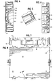
- FIG. 1 shows a pallet 10 of the present invention.
- the pallet 10 can be made of a variety of materials.
- the pallet 10 is made of rotationally molded plastic.
- the construction is preferably a linear low-density PE (LLDPE).
- LLDPE linear low-density PE
- the wall thickness can vary as needed, but with LLDPE, a wall thickness of 4.75 mm (0.19 inch) has proven acceptable for use with a pallet. At this thickness, a uniform wall thickness has an acceptable tolerance of 0.010 inch per inch.
- Other plastics employed in rotational molding processes are the polyolefins, including the preferred PE and polypropylene (PP), polyvinyl-chloride (PVC), polycarbonates, and nylon. These plastics can be used with a variety of resins and additives to meet particular needs or desires.
- the pallet 10 is illustrated with a deck 12 and an underside 14.
- the walls of the pallet 10 have an outer surface 16 (i.e., the load-bearing surface on the deck 12) and an inner surface 18.
- the deck 12 and the underside 14 are constructed of a unitary, continuous wall that bends, arches, or curves along all edges and structural features. Portions of the inner surface 18 of the underside 14 extend toward the inner surface 18 of the deck 12 to provide structural support to the deck 12 when a load stresses the deck 12 as more fully detailed below. There are no lattice walls or other open framework abutting the deck to provide support.
- the deck 12 is substantially flat. Although possible in others embodiments, the deck is not shown to be prestressed in an upwardly bent manner.
- the deck 12 includes hand holds 20 and nubbins 22, which may be replaced in other embodiments by other raised portions.
- the load-bearing outer surface 16 of the deck 12 has a smooth top for general use but may instead be ribbed for use with a continuous feed press.
- substantially flat includes but is not limited to, hand holds 20, nubbins 22, a slight upward bend, or ribbing (not shown).
- the underside 14 includes two outer legs 30 and 32.
- Each leg 30 and 32 includes a side wall portion 34 and 36 respectively and a bottom portion 38 and 40 respectively and an inner wall 42 and 44 respectively.
- the bottom portions 38 and 40 are adapted to contact the ground or floor when the pallet 10 is upright.
- Each leg 30 and 32 extends to the farthest edges 46 and 48 of the deck 12 respectively.
- the legs 30 and 32 are designed for maximum load and pallet stability.
- the underside 14 also includes a center leg 50.
- the center leg 50 is equidistant between and parallel to the two outer legs 30 and 32.
- the center leg 50 includes two side wall portions 52 and 54.
- the center leg 50 also has inside walls 56 and 58 as part of the underside 14.
- the center leg 50 is in a bottom plane, of which a portion is adapted to contact the ground or floor when the pallet 10 is upright.
- the underside 14 includes structural features to maximize the load-bearing capacity of the pallet 10. As best seen in Figure 3, those features in the center leg 50 include two concave arched bottom recesses 70, 71 and a series of triangular depressions 72, 73, 74, 75, 76, 77, that are a portion of the underside member of the pallet 10, as shown in Figure 3. One recess 70 is shown in cross section in Figure 4.
- the arched bottom recess 70 in the center leg 50 is a structural feature designed to maximize the load-bearing capacity of the pallet 10.
- the arched bottom recess is concave in the center portion of the underside 14.
- the arched bottom recess 70 arches toward the deck 12 and inwardly from the bottom plane.
- the arched bottom recess 70 is arcuate in both directions so that a downward load on the load-bearing surface 16 of the deck 12 is transferred downwardly and outwardly. When arcuate in both directions from both opposing sides of the center leg, bottom recess 70 will be at a deepest point in the center of the depression, such as 82.
- the arched recess 70 transfers loads and includes concave depressions 80, 81, 82, 83 and 84 to simultaneously give the pallet vertical strength.
- the arched recess 70 does not, directly contact the inner surface 18 of the deck 12.
- there may be such direct contact recess 70 has numerous concave depression 80, 81, 82, 83, 84 extending to contact the deck inner surface 18 as shown in Figures 2 and 4.
- the inner surface 18 of each depression 80-84 is in contact with the inner surface 18 of the deck 12 so a load on the deck 12 is transferred to each depression 80-84.
- the depressions do not contact the deck but are in close proximity thereto.
- the depressions 80 and 84 that are closest to the side walls 52 and 54 extend farther inward from the arched recess 70 to contact the inner surface 18 of the deck 12 because the arched recess 70 is closer to the bottom plane at that point. There is a gap between each adjacent depression 80-84. In other embodiments there is no gap.
- the arched recess 70 does not extend from one side wall 52 of the center leg 50 to the opposing side wall 54, but may do so in other embodiments.
- the pallet 10 includes substantially triangular side impact depressions 72, 73, 74, 75, 76, 77, which are incorporated in the center leg 50 between the arched recess 70 and each side wall 52 and 54.
- the triangular shaped side impact depressions 72-77 each have a rounded corner 85-90 respectively adjacent the inner surface 18 of the side walls 52 and 54 of the pallet 10.
- Triangular is meant to be interpreted broadly to include the preferred rounded corners and any three sided shape, such as a tear drop where one side is completely rounded, but a rounded corner 85-90 is still adjacent the inner surface 18 of the side walls 52 and 54.
- depressions 72-74 and 75-77 it is preferred that a portion of adjacent depressions are in contact with adjacent corners.
- the two corners each that do not contact the side walls (52 and 54 respectively) contact the adjacent corners of the other triangular depressions in the series 72 and 74, and 75 and 77 respectively.
- Depressions 73 and 76 as shown in Figure 3, are shorter to accommodate a recessed area 92, but this corners 86 and 89 are in contact with the side walls 52 and 54, and the distal corners are aligned with the adjacent corners of the other triangular depressions in the series 72 and 74, and 75 and 77 respectively.
- Depressions 73 and 76 may not have additional concave depressions if they contact the inner surface 18 of the hand hold 20.
- Triangular shaped side impact depressions 72, 74, 75 and 77 show three concave depressions (i.e., 91) in each extending to and contacting the inner surface of the deck 12. It is to be understood that depressions 72, 74, 75 and 77 may in other embodiments extend to have an inner surface in contact with the inner surface of the deck 12.
- a example of a concave depression 91 can however be seen in triangular shaped side impact depression 77 per Figures 3 and 5. As best seen, in Figure 5 through section 4-4, the concave depressions (i.e., 91) assist with distributing both vertical and horizontal stresses.
- the impact depressions 72-77 are designed to resist side impact in that any force or side impact is dissipated throughout the side walls 52 and 54 and into the rounded corners 85-90 of the impact depressions 72-77. Also, a triangular shape depression provides internal reinforcement to the deck 12 and other adjacent triangular depressions when the wall sections abut.
- the inner walls 42 and 44 and the side wall portions 56 and 58 of the center leg 50 and planar section 94 and 96 respectively form a pair of spaced openings for machinery such as pallet feeding equipment or the fork tines of a fork lift.
- the pallet 10 additionally provides for a lobed recessed structure 98 as shown in Figures 3 and 6 (in cross section) with the preferred two such structures 98 on each planar section 94 and 96 extending inwardly toward the deck 12.
- Each lobed recessed structure 98 has a substantial portion of its area (in a parallel cross section with the pallet) in contact 99 with the inner surface 18 of the deck 12.
- the lobed recessed structures 98 do not have additional depressions like the arched bottom recess 70 and the triangular shaped depressions 72, 74, 75, and 77.
- the walls 100 of lobed recessed structures 98 are slightly tapered inwardly toward the deck contact area 99, and all corners are rounded. In other embodiments, the slight inward taper and/or the rounded corners are not present.
- the lobed recessed structures 98 are also designed to prevent damage to the pallet 10.
- the primary function is to resist horizontal loads and stresses on the pallet 10.
- Lobed recessed structures 98 in appropriate locations resists outward pressure from a load either from the weight on the pallet or from being lifted, such as by fork lift tines.
- the pallet 10 with a lobed recessed structure 98 normally has contact at the deck contact area 99 with an opposing inner smooth surface 18 on the deck so stress on the load-bearing surface 16 is directed down and out through the lobed recessed structure 98.
- lobed recessed structure 98 is illustrated and described in connection with a depression having four lobes, it can be adapted for use with a variety of geometric shapes including a pattern with six lobes as shown in Fig. 9.
- the pallet has other features that provide additional benefits. These feature may be omitted in other embodiments.
- the hand hold 20 may extend below the deck 12 to provide a means for handling the pallet 10.
- nubbins 22 may extend above the deck 12.
- the nubbins 22 may provide a variety of functions, such as locking the deck.
- the nubbins 22 extend above the load-bearing surface of the deck 12 and preferably do so above the outer legs 30 and 32.
- the legs 30 and 32 would have a corresponding recess 101 (as shown in Figures 2 and 3) to accommodate a nubbin 22.
- the nubbins 22 may be called a stacking lip.
- Nubbins 22 are along the rounded edges 46 and 48 to assist in stacking or identifying the rounded edge for use in certain processes using a pallet. In other embodiments, nubbins, especially extending the entire length of a rounded edge, may be used for load containment.
- Recessed area 92 as shown in side wall 52 in Figure 1 has variety of uses. It may be fortified against impact by triangular depression 76.
- the recessed area 92 may be used for a label, tag, or thick insert for bar coding, identification, or logos.
- the label, tag, or thick insert can be as deep as the recess or very thin so that it will not extend beyond the side wall 52. In other embodiments, there is no area 92.
- the pallet 10 includes banding slots 103 along the edges of the deck 12. Banding slots 103 facilitate bands surrounding the goods on the pallet 10.
- the banding slot 103 preferably has another corresponding banding slot at the opposite edge of the pallet 10. In other embodiments there are no banding slots or, if banding slots are present, there are no corresponding slots as staked.
- the pallet 10 has cavities 104 and 105 adapted to accommodate reinforcement bars, such as steel bars. In others embodiments, these cavities are omitted.
- the steel bar cavities 104 and 105 are on the underside 14 of the pallet 10 extending in the two partially planar sections 94 and 96 and the side wall portions 56 and 58 of the center leg 50. In other embodiments, the cavities, if present, are located elsewhere.
- a steel bars are L-shaped for use in cavities 104 and 105 extending from the planar sections 94 and 96 to the side wall portions 56 and 58.
- the steel bar cavities 104 and 105 have depressions 106 and 107 to simultaneously give the cavities 104 and 105 strength and would help add support to the deck 12 when a load is applied on the deck 12.
- the depressions are omitted.
- the portion of the cavities 104 and 105 adjacent the deck 12 could extend immediately adjacent the deck 12 so that a bar in the cavities 104 and 105 could reinforce the deck 12.
- a capture area 109 could be formed in or through planar sections 94 or 96.
- a reinforcing steel bar may extend across the entire underside 14 of the pallet 10.
- a reinforcing steel bar may be adjacent the inner wall 42, extend into cavity 104 in the planar section 94 and up the wall portion 56 then across a recess in the bottom plane into the cavity 105 at wall portion 58 bending into the planar section 96 and up the inner wall 44.
- a reinforcement bar extends across the entire underside 14, but a shorter bar may be acceptable.
- the underside could include end pins 111, preferably on a capture area 109.
- four bar clamping locators, i.e., 113 can be used to accommodate bars.
- Rotational molding is the preferred method of manufacturing one-piece, hollow, continuous wall, strong, durable, lightweight pallets. It also is well adapted for uniform wall thicknesses with no problematic thinning in the extremities of the pallet. Further, it allows for a pallet that is resistant to stress-cracking and corrosion. Rotational molding provides excellent load-bearing properties with minimal stressed areas. Rotational molding also allows for metal inserts as integral parts. With rotational molding, complex and varied shapes can be formed to make hollow, lightweight pallets.
- Rotational molding uses heat to melt and fuse plastic resin in a closed hollow mold. Rotational molding is compatible for use with complex molds with such structural features.
- An initial step includes loading a plastic material or resin in a hollow mold that will be closed.
- the plastic resin can be either a liquid or powder.
- the next step is heating and fusing the resin. Time and temperature of heating will depend on the plastic used, wall thickness of the finished product, and type of mold used. As an example, polyethylene can be heated to 288 to 343°C (550 degrees F to 650 degrees F) for 10 to 25 minutes.
- the mold is continuously rotated on two axes at low speed. As heat penetrates the mold, resin adheres to the entire inside surface (all inner surfaces) of the mold until completely fused. The mold is heated to the fusion temperature while continuing to rotate allowing a thin layer of plastic material to deposit from the heated liquid plastic pool.
- the molded resin is cooled. Cooling is preferably gradual while the mold is still rotating. It may be air or water cooled, preferably with a spray or a mist.
- the cooled finished product solidifies, regaining strength and retaining the shape of the mold.
- the finished product, a pallet is removed from the opened mold.
Landscapes
- Engineering & Computer Science (AREA)
- Mechanical Engineering (AREA)
- Pallets (AREA)
Claims (17)
- Hohle Palette (10) mit einer oberseitigen Wandung (12), einer die oberseitige Wandung (12) stützenden Unterseite (14), wobei die Unterseite (14) eine Vielzahl an äußeren Aufstandstegen (30,32) und einen mittleren Aufstandsteg (50) aufweist, der sich zwischen den äußeren Aufstandstegen (30,32) befindet, so dass beim Gebrauch der Palette (10) nach unten gerichtete Belastungen über den mittleren Aufstandsteg (50) übertragen werden, dadurch gekennzeichnet, dass der mittlere Aufstandsteg (50) eine gewölbte konkave Ausnehmung (70,71) aufweist, die in Richtung auf die oberseitige Wandung (12) hin gewölbt ist, wobei die Ausnehmung (70,71) einen Teil einer Wandung des mittleren Aufstandsteges (50) bildet, so dass beim Gebrauch der Palette (10) durch die gewölbte Ausnehmung (70,71) Lasten auf der oberseitigen Wandung (12) nach unten hin übertragen werden.
- Palette (10) nach Anspruch 1, wobei die gewölbte Ausnehmung (70,71) in beiden Richtungen ausgehend von beiden einander gegenüberliegenden Seiten des mittleren Aufstandsteges (50) bis zu einem zuinnerst liegenden Punkt in der Mitte der Ausnehmung (70,71) hin gekrümmt ist.
- Palette (10) nach Anspruch 1 oder 2, wobei der gewölbte Abschnitt (70,71) konkav geformte Vertiefungen (80-84) aufweist, die sich in Richtung auf die oberseitige Wandung (12) hin erstrecken und mit dieser in Berührung stehen, sobald auf die oberseitige Wandung (12) eine Last aufgebracht wird.
- Palette (10) nach einem der Ansprüche 1 bis 3, wobei die gewölbte konkave Ausnehmung (70,71) frei von ebenen Oberflächen, rechten Winkeln, scharfen Kanten oder Ecken ist.
- Palette (10) nach einem der Ansprüche 1 bis 4, wobei die Palette (10) aus einer einheitlichen, einstückigen zusammenhängenden Kunststoffwandung besteht.
- Palette (10) nach einem der Ansprüche 1 bis 5, welche ferner Stege (22) umfasst, die aus der oberseitigen Wandung (12) nach oben herausragen und sich oberhalb der äußeren Aufstandstege (30,32) erstrecken.
- Palette (10) nach Anspruch 6, welche ferner zueinander entsprechende Ausnehmungen (101) in den äußeren Aufstandstegen (30,32) der Palette aufweist, die dazu bestimmt sind, die Stege (22) einer anderen Palette (10) aufzunehmen.
- Hohl ausgebildete, eine kontinuierliche Oberfläche aufweisende Palette (10) mit einer oberseitigen Wandung (12) und einer Vielzahl an Aufstandstegen (30,32,50) unterhalb der oberseitigen Wandung (12), deren jeder eine Wandung mit einer inneren (18) und einer äußeren Oberfläche (16) aufweist, dadurch gekennzeichnet, dass der Boden wenigstens eines der mehreren Aufstandstege (30,32,50) eine im Wesentlichen dreieckförmige Vertiefung (72-77) mit einem abgerundeten Eckenwandungsabschnitt (85-90) aufweist, und zwar in der Nähe der inneren Oberfläche einer Seitenwandung (52,54) des Aufstandsteges (50) mit der Vertiefung (72-77).
- Palette (10) nach Anspruch 8, mit einer Vielzahl dreieckförmiger Vertiefungen (72-77) in dem Boden wenigstens eines der Vielzahl an Aufstandstegen (30,32,50), wobei jede Vertiefung (72-77) einen abgerundeten Eckenwandungsabschnitt (85-90) in der Nähe der Seitenwandung (52,54) des Aufstandsteges (50) mit Vertiefungen aufweist und wobei sich ein anderer abgerundeter Eckenabschnitt einer jeden Vertiefung (73-76) mit einer benachbarten Ecke einer benachbarten Vertiefung (72,74,75,77) in Berührung befindet.
- Palette (10) nach Anspruch 8 oder 9, welche ferner eine Ausnehmungsfläche (92) in der Seitenwandung (52,54) umfasst, wobei sich ein abgerundeter Eckenwandungsabschnitt (85-90) der im Wesentlichen dreieckförmigen Vertiefung (73,76) mit der Ausnehmungsfläche (92) in Berührung befindet.
- Aus Kunststoff bestehende einstückige, hohle, eine kontinuierliche Wandung aufweisende Palette (10), welche Palette (10) eine im Wesentlichen ebene obere Wandung (12), eine Vielzahl an Aufstandstegen (30,32,50) und teilweise ebene Wandungsabschnitte (94,96) zwischen den Aufstandstegen (30,32,50) an einer Unterseite (14) der Palette (10) aufweist, gekennzeichnet durch eine mit lappigen Ausnehmungen versehene Struktur (98) in wenigstens einer der teilweisen ebenen Wandungsabschnitte (94,96) der Unterseite (14) der Palette (10), wobei die mit lappigen Ausnehmungen versehene Struktur (98) sich in der Nähe der oberseitigen Wandung (12) befindet, um diese zu stützen und zu stärken, sobald eine Last auf die Palette (10) aufgebracht wird.
- Palette (10) nach Anspruch 11, welche ferner Hohlräume (104,105) umfasst, die dazu bestimmt sind, Verstärkungsriegel aufzunehmen, die sich von den teilweise ebenen Wandungsabschnitten (94,96) bis zu einem benachbarten Aufstandsteg (30,32,50) erstrecken.
- Palette (10) nach Anspruch 1, bei welcher es sich um eine aus Kunststoff bestehende einstückige, geschlossene, einheitliche, eine kontinuierliche Wandung aufweisende Palette (10) mit einer inneren Wandungsoberfläche (18) und einer äußeren Wandungsoberfläche (16) handelt, wobei die äußere Wandungsoberfläche (16) die oberseitige Wandung (12) darstellt, welche eine im Wesentlichen ebene Wandung (12) bildet, wobei die Palette (10) einen teilweise ebenen Wandungsabschnitt (94,96) zwischen dem mittleren Aufstandsteg (50) und einem jeden der äußeren Aufstandstege (30,32) aufweist und wobei sich die äußeren Aufstandstege (30,32) an zwei einander gegenüberliegenden äußersten Kanten der Wandung (12) befinden, wobei die gewölbte konkave Ausnehmung (70,71) des mittleren Aufstandsteges (50) eine konkave Vertiefung (80-84) aufweist, die sich in Richtung auf die oberseitige Wandung (12) hin erstreckt, wobei sich die innere Oberfläche der Vertiefung (80-84)in der Nähe der inneren Oberfläche (18) der oberseitigen Wandung (12) befindet und wobei eine dreieckförmige Vertiefung (73, 76) mit einem abgerundeten Eckenabschnitt vorgesehen ist, deren innere Wandungsoberfläche sich in der Nähe der inneren Wandungsoberfläche (18) einer äußeren Seitenwandung (51,52) des mittleren Aufstandsteges (50) befindet.
- Palette (10) nach Anspruch 13, wobei die teilweisen ebenen Wandungsabschnitte (94,96) mit lappigen Ausnehmungen versehene Strukturen (98) einschließen mit inneren Wandungsoberflächen, die sich in der Nähe der inneren Wandungsoberfläche (14) der Wandung (12) befinden, wobei sich ein wesentlicher Teil der mit lappigen Ausnehmungen versehenen Struktur (98) in Berührung mit der inneren Wandungsoberfläche (18) der Wandung (12) befindet.
- Palette (10) nach Anspruch 13 oder 14, welche ferner Hohlräume (104,105) umfasst, die dazu bestimmt sind, Verstärkungsriegel aufzunehmen, die sich von den teilweise ebenen Wandungsabschnitten (94,96) bis zu einem benachbarten Aufstandsteg (30,32,50) hin erstrecken.
- Palette (10) nach einem der Ansprüche 13 bis 15, welche ferner Stege (22) umfasst, die sich oberhalb der äußeren Aufstandstege (30, 32) ausgehend von der Wandung (12) nach oben erstrecken.
- Palette (10) nach einem der Ansprüche 1 bis 16, gekennzeichnet durch eine gleichförmige Wandungsdicke.
Applications Claiming Priority (2)
| Application Number | Priority Date | Filing Date | Title |
|---|---|---|---|
| US09/821,475 US6386118B1 (en) | 2001-03-29 | 2001-03-29 | Pallet with stress resistant structure |
| US821475 | 2001-03-29 |
Publications (2)
| Publication Number | Publication Date |
|---|---|
| EP1245496A1 EP1245496A1 (de) | 2002-10-02 |
| EP1245496B1 true EP1245496B1 (de) | 2006-12-06 |
Family
ID=25233498
Family Applications (1)
| Application Number | Title | Priority Date | Filing Date |
|---|---|---|---|
| EP02250637A Expired - Lifetime EP1245496B1 (de) | 2001-03-29 | 2002-01-30 | Stressresistente Kunststoffpalette |
Country Status (6)
| Country | Link |
|---|---|
| US (1) | US6386118B1 (de) |
| EP (1) | EP1245496B1 (de) |
| AT (1) | ATE347519T1 (de) |
| DE (1) | DE60216533T2 (de) |
| HK (1) | HK1049317B (de) |
| MX (1) | MXPA02002272A (de) |
Families Citing this family (31)
| Publication number | Priority date | Publication date | Assignee | Title |
|---|---|---|---|---|
| US6807911B2 (en) * | 2001-03-29 | 2004-10-26 | Jeco Plastic Products, Llc | Pallet with stress resistant structure |
| US6708628B2 (en) | 2001-10-16 | 2004-03-23 | Conrad Herring | Load bearing structure for composite ecological shipping pallet |
| US20050193927A1 (en) * | 2001-10-16 | 2005-09-08 | Herring Conrad C. | Rackable composite shipping pallet for transporting and storing loads |
| US6857377B2 (en) * | 2001-10-16 | 2005-02-22 | Conrad C. Herring | Load bearing structure for a shipping pallet |
| US7124889B2 (en) * | 2003-03-17 | 2006-10-24 | Mexico Plastic Company | Rolled film and pallet construction |
| US6997113B1 (en) * | 2003-10-14 | 2006-02-14 | The Fabri-Form Company | Pallet |
| US7048118B2 (en) * | 2003-10-30 | 2006-05-23 | Sonoco Development, Inc. | Support post with locking feature |
| USD517702S1 (en) | 2004-04-14 | 2006-03-21 | Oliver James E | Pier cap for capping foundation pier for manufactured house |
| US7313892B1 (en) * | 2004-05-13 | 2008-01-01 | Oliver James E | Support for manufactured housing |
| US7726248B2 (en) * | 2004-10-07 | 2010-06-01 | Shuert Technologies, Llc | Twin sheet pallet |
| US20060081158A1 (en) * | 2004-10-19 | 2006-04-20 | Fitzpatrick Technologies, L.L.C. | Pultrusion pallet |
| US20060201400A1 (en) * | 2005-02-18 | 2006-09-14 | Moore Roy E Jr | Plastic pallet having deck suspension system |
| US20070017422A1 (en) * | 2005-07-19 | 2007-01-25 | Fitzpatrick Technologies, Llc | Pallet with composite components |
| US20070017423A1 (en) * | 2005-07-19 | 2007-01-25 | Ingham Terry L | Pallet With Recycled Components |
| USD548924S1 (en) | 2006-01-30 | 2007-08-14 | Ccbcc Operations, Llc | Pallet |
| US7779763B2 (en) * | 2006-12-19 | 2010-08-24 | Schoeller Arca Systems Services Gmbh | Transport pallet |
| WO2009042872A1 (en) * | 2007-09-26 | 2009-04-02 | Fitzpatrick Technologies | Pallet with lead board |
| US20100095875A1 (en) * | 2008-10-20 | 2010-04-22 | Magline, Inc. | Pallet with floor clearance |
| DE102011008136B4 (de) | 2011-01-08 | 2012-10-11 | A&A Logistik-Equipment GmbH & Co. KG | Fördermittel mit im Rotationssinterverfahren hergestellter Tragstruktur |
| US10414542B2 (en) * | 2017-08-29 | 2019-09-17 | Walmart Apollo, Llc | Concave-pallet design with a lip |
| US20190185205A1 (en) * | 2017-12-15 | 2019-06-20 | Shuert Technology, Llc | Molded plastic pallet having a snap in signal transmitter and method of making same |
| US10759561B2 (en) | 2017-12-15 | 2020-09-01 | Shuert Technology, Llc | Molded plastic pallet having a snap in signal transmitter and method of making same |
| US11554895B2 (en) | 2018-11-13 | 2023-01-17 | Chep Technology Pty Limited | Half-size plastic pallet with removable pallet support legs |
| WO2020187401A1 (de) * | 2019-03-19 | 2020-09-24 | Paul Craemer Gmbh | Palette mit stapel-anschlägen auf dem palettendeck |
| CN213992822U (zh) | 2020-04-23 | 2021-08-20 | 革新(厦门)运动器材有限公司 | 一种吹塑桌板 |
| US11524812B2 (en) * | 2020-04-28 | 2022-12-13 | Inno-Sports Co., Ltd. | Blow-molded unitary structure with enhanced strength |
| US11564494B2 (en) | 2020-07-27 | 2023-01-31 | Inno-Sports Co., Ltd. | Blow-molded unitary structure with enhanced strength |
| US11564492B2 (en) | 2020-07-27 | 2023-01-31 | Inno-Sports Co., Ltd. | Blow-molded unitary structure with enhanced strength |
| CN216123992U (zh) | 2021-04-20 | 2022-03-25 | 革新(厦门)运动器材有限公司 | 一种折叠桌 |
| US11937695B2 (en) | 2021-11-01 | 2024-03-26 | Inno-Sports Co., Ltd. | Height-adjustable folding table |
| EP4311791A1 (de) * | 2022-07-29 | 2024-01-31 | Motherson Innovations Company Ltd. | Palette |
Family Cites Families (20)
| Publication number | Priority date | Publication date | Assignee | Title |
|---|---|---|---|---|
| US3750598A (en) | 1971-03-24 | 1973-08-07 | Continental Can Co | Impact absorbing corner structure |
| US4000704A (en) * | 1974-10-18 | 1977-01-04 | Burlington Industries, Inc. | Shipping pallet |
| GB1512450A (en) * | 1975-05-06 | 1978-06-01 | Mitsubishi Chem Ind | Plastics pallet |
| US4159681A (en) | 1977-10-03 | 1979-07-03 | Vandament Daniel D | Reinforced, light-weight pallet |
| USD276702S (en) | 1982-08-02 | 1984-12-11 | Florida Containers, Inc. | Stackable tray for magnetic tape |
| US4706576A (en) * | 1986-03-27 | 1987-11-17 | Barry James | Interlocking plastic shelving system |
| ES2000149A6 (es) | 1986-10-29 | 1987-12-16 | Codima | Estructura para lama de somieres |
| DE8911445U1 (de) * | 1989-09-26 | 1989-11-09 | Lin Pac Friedrich GmbH, 48455 Bad Bentheim | Rollpalette |
| US5168817A (en) | 1990-11-16 | 1992-12-08 | Inca Presswood-Pallets, Ltd. | One-piece pallet |
| US5092251A (en) * | 1991-05-23 | 1992-03-03 | Bergen Barrel & Drum Co. | Liquid containment pallet |
| US5419524A (en) | 1993-03-12 | 1995-05-30 | Evans; Leonard W. | Weight distribution pad for trailers |
| US5755162A (en) | 1994-06-10 | 1998-05-26 | The Fabri-Form Co. | Reinforced plastic pallet |
| US5582113A (en) | 1994-10-13 | 1996-12-10 | Langenbeck; Keith A. | Modular pallet |
| US5566624A (en) * | 1995-08-15 | 1996-10-22 | Trienda Corporation | Twin-sheet thermoformed pallet with high stiffness deck |
| US5769003A (en) * | 1996-09-05 | 1998-06-23 | Formall, Inc. | Keg pallet |
| US5868080A (en) * | 1996-11-18 | 1999-02-09 | Engineered Polymers Corp. | Reinforced plastic pallets and methods of fabrication |
| US6180203B1 (en) | 1997-04-09 | 2001-01-30 | Peter J. Unkles | Rotational moulding process |
| US6079339A (en) | 1998-05-26 | 2000-06-27 | Rubbermaid Incorporated | Shelving system |
| US6123032A (en) | 1998-10-07 | 2000-09-26 | Ohanesian; Harout | Thermoplastic pallet |
| US6289823B1 (en) * | 1999-08-18 | 2001-09-18 | Rehrig Pacific Company | Nestable pallet |
-
2001
- 2001-03-29 US US09/821,475 patent/US6386118B1/en not_active Expired - Fee Related
-
2002
- 2002-01-30 DE DE60216533T patent/DE60216533T2/de not_active Expired - Lifetime
- 2002-01-30 EP EP02250637A patent/EP1245496B1/de not_active Expired - Lifetime
- 2002-01-30 AT AT02250637T patent/ATE347519T1/de not_active IP Right Cessation
- 2002-02-28 MX MXPA02002272A patent/MXPA02002272A/es active IP Right Grant
-
2003
- 2003-02-21 HK HK03101341.1A patent/HK1049317B/en not_active IP Right Cessation
Also Published As
| Publication number | Publication date |
|---|---|
| HK1049317A1 (en) | 2003-05-09 |
| HK1049317B (en) | 2007-03-30 |
| ATE347519T1 (de) | 2006-12-15 |
| US6386118B1 (en) | 2002-05-14 |
| DE60216533T2 (de) | 2007-04-05 |
| DE60216533D1 (de) | 2007-01-18 |
| MXPA02002272A (es) | 2004-04-21 |
| EP1245496A1 (de) | 2002-10-02 |
Similar Documents
| Publication | Publication Date | Title |
|---|---|---|
| US6386118B1 (en) | Pallet with stress resistant structure | |
| US6807911B2 (en) | Pallet with stress resistant structure | |
| AU699906B2 (en) | Twin-sheet thermoformed pallet with high stiffness deck | |
| US7908979B2 (en) | Pallet having load bearing capabilities on which articles may be placed for storage and/or transportation | |
| US6962115B2 (en) | Blow molded pallet with pre-formed inserts | |
| US5950546A (en) | Double deck fold-up pallet | |
| US5391251A (en) | Method of forming a pallet | |
| US6458232B1 (en) | Process for the manufacturing of thermoplastic products with high creep strain resistance | |
| US6857377B2 (en) | Load bearing structure for a shipping pallet | |
| BR112016028310B1 (pt) | Elemento estrutural | |
| WO2004063035A1 (en) | Nestable pallet | |
| WO2010151106A1 (en) | An improved pallet | |
| US20170088309A1 (en) | Pallet and method of making a pallet | |
| US20040255828A1 (en) | Blow molded pallet with wave-like supports | |
| NZ207285A (en) | Thermoplastics drums;tubular body made from sheet and premoulded ends hot-plate welded to body | |
| CA2433123C (en) | Conveyorable plastic thermoformed pallet and method for making pallet | |
| AU707915B2 (en) | Lightweight plastic pallet | |
| HK1057736B (en) | Pallet with stress resistant structure | |
| US20090302508A1 (en) | Method of construction | |
| AU2021201723A1 (en) | Plastic container | |
| CA2142050A1 (en) | Pallet construction | |
| AU2006315094A1 (en) | A pallet |
Legal Events
| Date | Code | Title | Description |
|---|---|---|---|
| PUAI | Public reference made under article 153(3) epc to a published international application that has entered the european phase |
Free format text: ORIGINAL CODE: 0009012 |
|
| AK | Designated contracting states |
Kind code of ref document: A1 Designated state(s): AT BE CH CY DE DK ES FI FR GB GR IE IT LI LU MC NL PT SE TR |
|
| AX | Request for extension of the european patent |
Free format text: AL;LT;LV;MK;RO;SI |
|
| 17P | Request for examination filed |
Effective date: 20030301 |
|
| AKX | Designation fees paid |
Designated state(s): AT BE CH CY DE DK ES FI FR GB GR IE IT LI LU MC NL PT SE TR |
|
| 17Q | First examination report despatched |
Effective date: 20030514 |
|
| GRAP | Despatch of communication of intention to grant a patent |
Free format text: ORIGINAL CODE: EPIDOSNIGR1 |
|
| GRAS | Grant fee paid |
Free format text: ORIGINAL CODE: EPIDOSNIGR3 |
|
| GRAA | (expected) grant |
Free format text: ORIGINAL CODE: 0009210 |
|
| AK | Designated contracting states |
Kind code of ref document: B1 Designated state(s): AT BE CH CY DE DK ES FI FR GB GR IE IT LI LU MC NL PT SE TR |
|
| PG25 | Lapsed in a contracting state [announced via postgrant information from national office to epo] |
Ref country code: IT Free format text: LAPSE BECAUSE OF FAILURE TO SUBMIT A TRANSLATION OF THE DESCRIPTION OR TO PAY THE FEE WITHIN THE PRESCRIBED TIME-LIMIT;WARNING: LAPSES OF ITALIAN PATENTS WITH EFFECTIVE DATE BEFORE 2007 MAY HAVE OCCURRED AT ANY TIME BEFORE 2007. THE CORRECT EFFECTIVE DATE MAY BE DIFFERENT FROM THE ONE RECORDED. Effective date: 20061206 Ref country code: BE Free format text: LAPSE BECAUSE OF FAILURE TO SUBMIT A TRANSLATION OF THE DESCRIPTION OR TO PAY THE FEE WITHIN THE PRESCRIBED TIME-LIMIT Effective date: 20061206 Ref country code: NL Free format text: LAPSE BECAUSE OF FAILURE TO SUBMIT A TRANSLATION OF THE DESCRIPTION OR TO PAY THE FEE WITHIN THE PRESCRIBED TIME-LIMIT Effective date: 20061206 Ref country code: AT Free format text: LAPSE BECAUSE OF FAILURE TO SUBMIT A TRANSLATION OF THE DESCRIPTION OR TO PAY THE FEE WITHIN THE PRESCRIBED TIME-LIMIT Effective date: 20061206 Ref country code: DK Free format text: LAPSE BECAUSE OF FAILURE TO SUBMIT A TRANSLATION OF THE DESCRIPTION OR TO PAY THE FEE WITHIN THE PRESCRIBED TIME-LIMIT Effective date: 20061206 Ref country code: FI Free format text: LAPSE BECAUSE OF FAILURE TO SUBMIT A TRANSLATION OF THE DESCRIPTION OR TO PAY THE FEE WITHIN THE PRESCRIBED TIME-LIMIT Effective date: 20061206 |
|
| REG | Reference to a national code |
Ref country code: GB Ref legal event code: FG4D |
|
| REG | Reference to a national code |
Ref country code: CH Ref legal event code: EP Ref country code: CH Ref legal event code: NV Representative=s name: KIRKER & CIE SA |
|
| REG | Reference to a national code |
Ref country code: IE Ref legal event code: FG4D |
|
| REF | Corresponds to: |
Ref document number: 60216533 Country of ref document: DE Date of ref document: 20070118 Kind code of ref document: P |
|
| PG25 | Lapsed in a contracting state [announced via postgrant information from national office to epo] |
Ref country code: MC Free format text: LAPSE BECAUSE OF NON-PAYMENT OF DUE FEES Effective date: 20070131 |
|
| PG25 | Lapsed in a contracting state [announced via postgrant information from national office to epo] |
Ref country code: SE Free format text: LAPSE BECAUSE OF FAILURE TO SUBMIT A TRANSLATION OF THE DESCRIPTION OR TO PAY THE FEE WITHIN THE PRESCRIBED TIME-LIMIT Effective date: 20070306 |
|
| PG25 | Lapsed in a contracting state [announced via postgrant information from national office to epo] |
Ref country code: ES Free format text: LAPSE BECAUSE OF FAILURE TO SUBMIT A TRANSLATION OF THE DESCRIPTION OR TO PAY THE FEE WITHIN THE PRESCRIBED TIME-LIMIT Effective date: 20070317 |
|
| REG | Reference to a national code |
Ref country code: HK Ref legal event code: GR Ref document number: 1049317 Country of ref document: HK |
|
| PG25 | Lapsed in a contracting state [announced via postgrant information from national office to epo] |
Ref country code: PT Free format text: LAPSE BECAUSE OF FAILURE TO SUBMIT A TRANSLATION OF THE DESCRIPTION OR TO PAY THE FEE WITHIN THE PRESCRIBED TIME-LIMIT Effective date: 20070507 |
|
| NLV1 | Nl: lapsed or annulled due to failure to fulfill the requirements of art. 29p and 29m of the patents act | ||
| EN | Fr: translation not filed | ||
| PLBE | No opposition filed within time limit |
Free format text: ORIGINAL CODE: 0009261 |
|
| STAA | Information on the status of an ep patent application or granted ep patent |
Free format text: STATUS: NO OPPOSITION FILED WITHIN TIME LIMIT |
|
| 26N | No opposition filed |
Effective date: 20070907 |
|
| PG25 | Lapsed in a contracting state [announced via postgrant information from national office to epo] |
Ref country code: IE Free format text: LAPSE BECAUSE OF NON-PAYMENT OF DUE FEES Effective date: 20070130 |
|
| PG25 | Lapsed in a contracting state [announced via postgrant information from national office to epo] |
Ref country code: FR Free format text: LAPSE BECAUSE OF FAILURE TO SUBMIT A TRANSLATION OF THE DESCRIPTION OR TO PAY THE FEE WITHIN THE PRESCRIBED TIME-LIMIT Effective date: 20070727 Ref country code: GR Free format text: LAPSE BECAUSE OF FAILURE TO SUBMIT A TRANSLATION OF THE DESCRIPTION OR TO PAY THE FEE WITHIN THE PRESCRIBED TIME-LIMIT Effective date: 20070307 |
|
| PG25 | Lapsed in a contracting state [announced via postgrant information from national office to epo] |
Ref country code: FR Free format text: LAPSE BECAUSE OF FAILURE TO SUBMIT A TRANSLATION OF THE DESCRIPTION OR TO PAY THE FEE WITHIN THE PRESCRIBED TIME-LIMIT Effective date: 20061206 |
|
| PGFP | Annual fee paid to national office [announced via postgrant information from national office to epo] |
Ref country code: GB Payment date: 20090128 Year of fee payment: 8 |
|
| PG25 | Lapsed in a contracting state [announced via postgrant information from national office to epo] |
Ref country code: CY Free format text: LAPSE BECAUSE OF FAILURE TO SUBMIT A TRANSLATION OF THE DESCRIPTION OR TO PAY THE FEE WITHIN THE PRESCRIBED TIME-LIMIT Effective date: 20061206 Ref country code: LU Free format text: LAPSE BECAUSE OF NON-PAYMENT OF DUE FEES Effective date: 20070130 |
|
| PG25 | Lapsed in a contracting state [announced via postgrant information from national office to epo] |
Ref country code: TR Free format text: LAPSE BECAUSE OF FAILURE TO SUBMIT A TRANSLATION OF THE DESCRIPTION OR TO PAY THE FEE WITHIN THE PRESCRIBED TIME-LIMIT Effective date: 20061206 |
|
| GBPC | Gb: european patent ceased through non-payment of renewal fee |
Effective date: 20100130 |
|
| PG25 | Lapsed in a contracting state [announced via postgrant information from national office to epo] |
Ref country code: GB Free format text: LAPSE BECAUSE OF NON-PAYMENT OF DUE FEES Effective date: 20100130 |
|
| PGFP | Annual fee paid to national office [announced via postgrant information from national office to epo] |
Ref country code: CH Payment date: 20120125 Year of fee payment: 11 |
|
| PGFP | Annual fee paid to national office [announced via postgrant information from national office to epo] |
Ref country code: DE Payment date: 20120127 Year of fee payment: 11 |
|
| REG | Reference to a national code |
Ref country code: DE Ref legal event code: R082 Ref document number: 60216533 Country of ref document: DE Representative=s name: RAINER CALLIES, DE Ref country code: DE Ref legal event code: R082 Ref document number: 60216533 Country of ref document: DE Representative=s name: CALLIES, RAINER, DIPL.-PHYS. DR.RER.NAT., DE |
|
| REG | Reference to a national code |
Ref country code: CH Ref legal event code: PL |
|
| PG25 | Lapsed in a contracting state [announced via postgrant information from national office to epo] |
Ref country code: LI Free format text: LAPSE BECAUSE OF NON-PAYMENT OF DUE FEES Effective date: 20130131 Ref country code: CH Free format text: LAPSE BECAUSE OF NON-PAYMENT OF DUE FEES Effective date: 20130131 Ref country code: DE Free format text: LAPSE BECAUSE OF NON-PAYMENT OF DUE FEES Effective date: 20130801 |
|
| REG | Reference to a national code |
Ref country code: DE Ref legal event code: R119 Ref document number: 60216533 Country of ref document: DE Effective date: 20130801 |