EP1245518A2 - Stangenbildner - Google Patents
Stangenbildner Download PDFInfo
- Publication number
- EP1245518A2 EP1245518A2 EP02006837A EP02006837A EP1245518A2 EP 1245518 A2 EP1245518 A2 EP 1245518A2 EP 02006837 A EP02006837 A EP 02006837A EP 02006837 A EP02006837 A EP 02006837A EP 1245518 A2 EP1245518 A2 EP 1245518A2
- Authority
- EP
- European Patent Office
- Prior art keywords
- stacking section
- rake
- conveying direction
- bar former
- former according
- Prior art date
- Legal status (The legal status is an assumption and is not a legal conclusion. Google has not performed a legal analysis and makes no representation as to the accuracy of the status listed.)
- Granted
Links
Images

Classifications
-
- B—PERFORMING OPERATIONS; TRANSPORTING
- B65—CONVEYING; PACKING; STORING; HANDLING THIN OR FILAMENTARY MATERIAL
- B65H—HANDLING THIN OR FILAMENTARY MATERIAL, e.g. SHEETS, WEBS, CABLES
- B65H29/00—Delivering or advancing articles from machines; Advancing articles to or into piles
- B65H29/66—Advancing articles in overlapping streams
-
- B—PERFORMING OPERATIONS; TRANSPORTING
- B65—CONVEYING; PACKING; STORING; HANDLING THIN OR FILAMENTARY MATERIAL
- B65H—HANDLING THIN OR FILAMENTARY MATERIAL, e.g. SHEETS, WEBS, CABLES
- B65H31/00—Pile receivers
- B65H31/32—Auxiliary devices for receiving articles during removal of a completed pile
-
- B—PERFORMING OPERATIONS; TRANSPORTING
- B65—CONVEYING; PACKING; STORING; HANDLING THIN OR FILAMENTARY MATERIAL
- B65H—HANDLING THIN OR FILAMENTARY MATERIAL, e.g. SHEETS, WEBS, CABLES
- B65H33/00—Forming counted batches in delivery pile or stream of articles
- B65H33/12—Forming counted batches in delivery pile or stream of articles by creating gaps in the stream
-
- B—PERFORMING OPERATIONS; TRANSPORTING
- B65—CONVEYING; PACKING; STORING; HANDLING THIN OR FILAMENTARY MATERIAL
- B65H—HANDLING THIN OR FILAMENTARY MATERIAL, e.g. SHEETS, WEBS, CABLES
- B65H2301/00—Handling processes for sheets or webs
- B65H2301/30—Orientation, displacement, position of the handled material
- B65H2301/32—Orientation of handled material
- B65H2301/324—Inclined
-
- B—PERFORMING OPERATIONS; TRANSPORTING
- B65—CONVEYING; PACKING; STORING; HANDLING THIN OR FILAMENTARY MATERIAL
- B65H—HANDLING THIN OR FILAMENTARY MATERIAL, e.g. SHEETS, WEBS, CABLES
- B65H2405/00—Parts for holding the handled material
- B65H2405/30—Other features of supports for sheets
- B65H2405/32—Supports for sheets partially insertable - extractable, e.g. upon sliding movement, drawer
- B65H2405/323—Cantilever finger member, e.g. reciprocating in parallel to plane of handled material
Definitions
- the present invention relates to a vertical bar former for Forming vertical stacks, so-called bars, from printed products, which are delivered in a stream of shed.
- Such known bar formers have a product feed Feed the scale flow in a conveying direction and a straight line Stack distance on.
- the stacking section follows the product feed and has an upper start and a lower end. Furthermore, in the area of the stacking section for the continuous formation of Rods several handling elements are provided.
- top of the stacking section is opposite to the lower beginning inclined in the conveying direction so that the in the area of the stacked printed products with their leading edge (Fold) automatically by gravity against one in the area of the stacking line the intended stop.
- This allows you to perform of the printed products through the product feed and when holding them down the product back less forces are applied, whereby smearing of the printed products by hold-down elements or pressure belt is avoided.
- the handling elements at least one displaceable along the stacking path and have rakes retractable into the stacking section, the upper one End position above the scale flow supplied by the product guide is arranged.
- the upper end position i.e. the waiting position the rake is thus above the shingled stream supplied, so that the rake touches the bar from above. This will Rod end held securely so that it cannot slip.
- the handling elements at least one displaceable along the stacking route Lowering fork, in the displacement of which a first feed for end plates is arranged.
- the lowering fork is used in a known manner, the Lower the bar during the bar forming process.
- This first feed for end plates is thus arranged in an area seen both in terms of space and in terms of time is not critical.
- the handling elements one slidable along the stacking path and into the Stackable retractable holding rake, in the displacement of which one second feed for end plates is arranged.
- a second end plate for example an upper end plate, after which the holding rake is placed from above this has been moved along the stacking route.
- the handling elements one slidable along the stacking path and into the Stackable retractable separating rake, the tines with a support tape are provided when the rake is withdrawn from the stacking section via a roller provided at the tip of the tine can be unrolled.
- a separating rake with a rollable Support tape or trigger tape can be prevented from a relative movement between the rake and the product stack above it takes place by the overlay during the retraction of the rake is rolled over the roll. This prevents the to transferring printed products are damaged or smeared.
- the product feed has at least three in the conveying direction and transverse to the conveying direction spaced pressure belts. With such pressure belts the shingled stream of printed products supplied can be accelerated and pre-pressed into the stacking section, at the same time proper orientation of each individual printed product is ensured.
- the product feed can be designed so that the position of the two outer pressure belts is adjustable transversely to the conveying direction. This makes it easy to adjust guaranteed because the middle pressure belt even with different Formats can maintain its location, while only the two outer pressure belts must be adjusted.
- An adjustability the outermost pressure belt has the additional advantage that each printed product of the shingled stream supplied is always at the top and is held and pressed when it is inserted into the stacking section becomes.
- a total of six pressure belts in the product feed are preferred provided, the two innermost pressure belts transverse to the conveying direction are not adjustable, and being the relative length of the two outermost Pressure belt and the relative position of the neighboring one Pressure belt is adjustable across the conveying direction.
- Such Product feeding can also be done with multi-pronged rakes at different Format sizes are used because of the adjustability of the Pressure belts easily adapt to different Formats is possible.
- the Product feed and the handling elements on a common Base attached is adjustable.
- a displacement device be provided, which is a fully formed rod from the Area of the stacking section guided on all sides to a pressing and strapping unit passes. This results in a fully automatic mode of operation the machine, while ensuring that the fully formed Also at the handover to the pressing and strapping unit is guided on all sides.
- Fig. 1 shows a side view of a vertical bar former for forming from bars S from printed products delivered in a shingled stream P.
- the bar former has a base frame 10
- Product feed 12 for feeding the scale flow P in one Direction of conveyance F, with a straight line on the product feed 12
- Stacking path 14 with an upper start in the area of the product feed P and a lower end connects.
- multiple handling elements are provided to continuously individual rods S from the delivered scale stream P. form.
- it is a separating rake 16, one Holding rake 18 and a lowering fork 20, each along the stacking path 14 are slidably attached to the base frame 10.
- the Lowering fork 20 slidable along a guide 22, whereas the Separating rake 16 and the holding rake 18 can be moved along a guide 24 are. Both guides overlap along the stacking route 14th
- Both the separating rake 16 and the holding rake 18 are in the stacking section 14 retractable (see illustration in Fig. 1) and can with the help of actuating cylinders 26 to the rear from the area of the stack section 14 be brought out.
- the stack path 14 is inclined, in such a way that the upper beginning of the stack section 14 with respect to the vertical in the conveying direction F (and not against the conveying direction). hereby includes a stop provided on the back of the conveyor line 14 28 with the horizontal an acute angle ⁇ , for example is about 70 °, and that opens in the conveying direction.
- a first feed 34 for end plates 36 is provided.
- a second feed 30 for end plates 32 is provided.
- a stacking plate can be fed through the feeds 30 and 34 32 or 36 are introduced into the stack section 14, the Lowering fork 20 takes over an end plate 36 from the feed 34 and the holding rake 18 takes over an end plate 32 from the guide 30, which is explained in more detail below.
- the displacement device 40 has a plurality of pivotable holding brackets 42, which are provided with pins 44, which when folded Press brackets 42 onto the top of the upper end plate 32. Above the bracket 42, a lateral guide 46 for the rod S may be provided.
- the product feeder 12 has a plurality of upper and lower pressure belts 50, 52 on, between them the shingled stream P from Lead printed products while pressing.
- the upper pressure belts 50 are longer than the lower pressure belts 52 and the front end of the upper pressure belt 50, 52 extends into the upper end of the stacking section 14.
- In this area 28 are parallel on the side of the stop and essentially in alignment with this a plurality of trigger belts 54 provided with the help of the product spine (fold) in the stacking line 14 imported printed products is pulled down.
- the upper end position of the separating rake 16 lies and the holding rake 18 above that through the product guide 12 fed scale stream P when its products in the stacking section 14 occur. This means that the rakes 16, 18 during a lowering movement dive through the stream of scale. Because the top Pressure belt 50 of the product feed 12 into the area of the stacking section are introduced (see FIG. 1), the rakes 16, 18 must comb the top pressure belt 50.
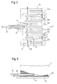
- Fig. 2 shows a top view this arrangement in detail.
- Fig. 2 is a plan view of the separating rake 16 is shown with combs the pressure belt 50a-50f of the product feed 12. simultaneously can be seen that the tines of the separating rake 16 by in the Stop 28 provided slots are passed and that the Separating rake 16 with the help of the actuating cylinder 26 in the direction of the double arrow 27 into and out of the stack section 14.
- the separating rake 16 has five in the illustrated embodiment Tines on, one tine between two adjacent pressure belts 50a, 50b, 50c, 50d and 50e, 50f comes to rest. When lowering of the separating rake 16 along the guide 24 would come the tines Computing 16 with the pressure belt of the product feed 12, so that the Rake 16 can pass through the product feed 12.
- the separating rake 18 is designed in the same way as the separating rake 16 and is from the position shown in Fig. 1 together with the separating rake 16 lowered, with the start of the lowering movement both rakes are directly one above the other.
- the separating rake 16 and the holding rake 18 shoot together in the Stack distance 14 after a separator 60 a certain Gap in the shingled stream created and after that gap up has reached the area of the stack section 14. Then be this lowered at the same time so that it with the pressure belt 50a - 50f comb the product feeder 12.
- the holding rake 18 is then moved at the same speed as the lowering fork 20, so that the fully formed rod between the lowering fork 20 and the Holding rake 18 is clamped.
- the separating rake 16 is used with the usual Rod formation speed lowered, so that on this one forms new partial stack.
- the bar builder a format adjustment that acts in the conveying direction F and a format adjustment that is transverse to the conveying direction F of the conveyed Products P works.
- the product feed in the illustrated Embodiment six upper pressure belts 50a - 50f on the a base 70 are attached. All pressure belts run parallel and each take a prong of rakes 16 and 18 between them. As indicated in Fig. 2 by double arrows, the two can outermost pressure belts 50a and 50f transverse to the product conveying direction F can be adjusted (arrows A, B), with an additional relative adjustment between the two outermost pressure belts 50a and 50b or 50e and 50f is possible (arrows C, D). This ensures that each product on both of them lying transversely to the conveying direction extreme edges of pressure belts (pressure belts 50a and 50f) is held and that the remaining pressure belts evenly over the Area of the product are distributed.
- Base 70 can be reached along the double arrow 72.
- the guide 24 of the rake 16, 18 and the guide 22 of the lowering fork 20 is connected by simply moving the base 70 along the double arrow 72 an adjustment of all required settings causes.
- FIG. 3 shows an alternative embodiment of a holding rake 18 ' the transfer of a formed partial stack S to the lowering fork 20 or the end plate 36 located on this.
- a deflection roller at the ends of each prong of the separating rake 18 ' 82 is provided, with a support belt around each deflection roller 82 80 is performed.
- the rake 18 ' is pulled back, the upper run of the support tape 80 at the left end (in Fig. 3), so that when withdrawing the rake 18 'simultaneously with the lower run of the Support tape 80 this can roll around the pulley 82.
- the partial stack S located on the support belt 80 is unrolled without that a relative movement between the rake 18 'and the sub-stack S takes place. In this way, an extremely gentle transfer of the Partial stack formed.
- the separation device 60 to introduce a gap in the shingled stream in provided such a height above the ground that it can move from one to the other the operator standing on the floor can be easily reached.
Landscapes
- Engineering & Computer Science (AREA)
- Mechanical Engineering (AREA)
- Feeding Of Articles By Means Other Than Belts Or Rollers (AREA)
- Forming Counted Batches (AREA)
- Radiation-Therapy Devices (AREA)
- Holo Graphy (AREA)
- Grinding Of Cylindrical And Plane Surfaces (AREA)
- Pile Receivers (AREA)
- Superconductors And Manufacturing Methods Therefor (AREA)
Abstract
Description
- Fig. 1
- eine stark vereinfachte schematische Seitenansicht eines vertikalen Stangenbildners;
- Fig. 2
- eine stark vereinfachte Draufsicht auf die Produktzuführung mit eingeführtem Rechen; und
- Fig. 3
- eine vereinfachte Seitenansicht eines mit einem Auflageband versehenen Rechens bei der Übergabe eines Produktstapels.
- 10
- Grundgestell
- 12
- Produktzuführung
- 14
- Stapelstrecke
- 16
- Trennrechen
- 18
- Halterechen
- 18'
- Halterechen
- 20
- Senkgabel
- 22
- Führung für Senkgabel
- 24
- Führung für Trenn- und Halterechen
- 26
- Stellzylinder
- 27
- Verstellrichtung der Rechen
- 28
- Anschlag
- 30
- zweite Zuführung
- 32
- obere Endplatte
- 34
- erste Zuführung
- 36
- untere Endplatte
- 40
- Verschiebeeinrichtung
- 42
- Haltewinkel
- 44
- Zapfen
- 46
- seitliche Führung
- 50
- obere Andruckriemen
- 50a - 50f
- obere Andruckriemen
- 52
- untere Andruckriemen
- 54
- Abzugsbänder
- 60
- Trenneinrichtung
- 70
- Basis
- 72
- Verschieberichtung der Basis
- 80
- Auflageband
- 82
- Umlenkrolle
- F
- Förderrichtung
- P
- Produktstrom
- S
- Stange
- α
- Neigungswinkel
Claims (10)
- Vertikaler Stangenbildner zum Bilden von vertikalen Stangen (S) aus in einem Schuppenstrom angelieferten Druckprodukten (P), mit einer Produktzuführung (12) zum Zuführen des Schuppenstromes in einer Förderrichtung (F),
einer sich an die Produktzuführung (12) anschließenden, geradlinigen Stapelstrecke (14) mit einem oberen Anfang und einem unteren Ende, und
mehreren Handhabungselementen (16, 18, 20) im Bereich der Stapelstrecke zur kontinuierlichen Bildung von Stangen,
dadurch gekennzeichnet, daß
der obere Anfang der Stapelstrecke (14) gegenüber der Vertikalen in Förderrichtung (F) geneigt ist. - Stangenbildner nach Anspruch 1,
dadurch gekennzeichnet, daß
die Handhabungselemente zumindest einen entlang der Stapelstrecke (14) verschiebbaren und in die Stapelstrecke einfahrbaren Rechen (16, 18, 20) aufweisen, dessen obere Endposition (Warteposition) oberhalb des durch die Produktzuführung (12) zugeführten Schuppenstromes angeordnet ist. - Stangenbildner nach Anspruch 1,
dadurch gekennzeichnet, daß
die Handhabungselemente zumindest eine entlang der Stapelstrecke verschiebbare Senkgabel (20) aufweisen, in deren Verschiebeweg eine erste Zuführung (34) für Endplatten (36) angeordnet ist. - Stangenbildner nach Anspruch 1,
dadurch gekennzeichnet, daß
die Handhabungselemente einen entlang der Stapelstrecke (14) verschiebbaren und in die Stapelstrecke einfahrbaren Halterechen (18, 18') aufweisen, in dessen Verschiebeweg eine zweite Zuführung (30) für Endplatten (32) angeordnet ist. - Stangenbildner nach Anspruch 1,
dadurch gekennzeichnet, daß
die Handhabungselemente einen entlang der Stapelstrecke (14) verschiebbaren und in die Stapelstrecke einfahrbaren Trennrechen (18') aufweisen, dessen Zinken mit einem Auflageband (80) versehen sind, das beim Zurückziehen des Rechens (18') aus der Stapelstrecke (14) über eine an der Spitze der Zinke vorgesehene Rolle (82) abrollbar ist. - Stangenbildner nach Anspruch 1,
dadurch gekennzeichnet, daß
die Produktzuführung (12) mindestens drei in Förderrichtung (F) verlaufende und quer zur Förderrichtung (F) beabstandete Andruckriemen (50a - 50f) aufweist, wobei die relative Lage zumindest der beiden äußeren Andruckriemen (50a, 50f) quer zur Förderrichtung (F) einstellbar ist. - Stangenbildner nach Anspruch 6,
dadurch gekennzeichnet, daß
insgesamt sechs Andruckriemen (50a - 50f) vorgesehen sind, wobei die zwei innersten Andruckriemen (50c, 50d) quer zur Förderrichtung (F) nicht verstellbar sind, und wobei die relative Lage der beiden äußersten Andruckriemen (50a, 50f) sowie die relative Lage des dazu jeweils benachbarten Andruckriemens (50b, 50e) quer zur Förderrichtung (F) einstellbar ist. - Stangenbildner nach Anspruch 1,
dadurch gekennzeichnet, daß
die Produktzuführung (12) und die Handhabungselemente (16, 18, 18', 20) auf einer gemeinsamen Basis (70) befestigt sind, wobei die Relativlage zwischen Basis (70) und Stapelstrecke (14) in Förderrichtung verstellbar ist. - Stangenbildner nach Anspruch 1,
dadurch gekennzeichnet, daß
eine Einheit (60) zum Einbringen einer Lücke in den Schuppenstrom vorgesehen ist, die in einer solchen Höhe über dem Boden angeordnet ist, daß sie von einer auf dem Boden stehenden Bedienperson bequem erreicht werden kann, und daß eine Transporteinrichtung zum Weitertransport des Produktstromes zu der an dem oberen Ende der Stapelstrecke vorgesehenen Produktzuführung vorgesehen ist. - Stangenbildner nach Anspruch 1,
dadurch gekennzeichnet, daß
eine Verschiebeeinrichtung (40) vorgesehen ist, welche eine vollständig gebildete Stange (S) aus dem Bereich der Stapelstrecke (14) allseitig geführt an eine Preß- und Umreifungseinheit übergibt.
Applications Claiming Priority (2)
| Application Number | Priority Date | Filing Date | Title |
|---|---|---|---|
| DE10115251 | 2001-03-28 | ||
| DE10115251A DE10115251A1 (de) | 2001-03-28 | 2001-03-28 | Stangenbildner |
Publications (3)
| Publication Number | Publication Date |
|---|---|
| EP1245518A2 true EP1245518A2 (de) | 2002-10-02 |
| EP1245518A3 EP1245518A3 (de) | 2004-01-02 |
| EP1245518B1 EP1245518B1 (de) | 2006-06-07 |
Family
ID=7679362
Family Applications (1)
| Application Number | Title | Priority Date | Filing Date |
|---|---|---|---|
| EP02006837A Expired - Lifetime EP1245518B1 (de) | 2001-03-28 | 2002-03-25 | Stangenbildner |
Country Status (5)
| Country | Link |
|---|---|
| US (1) | US6889973B2 (de) |
| EP (1) | EP1245518B1 (de) |
| AT (1) | ATE328832T1 (de) |
| DE (2) | DE10115251A1 (de) |
| DK (1) | DK1245518T3 (de) |
Families Citing this family (5)
| Publication number | Priority date | Publication date | Assignee | Title |
|---|---|---|---|---|
| JP4254845B2 (ja) * | 2006-11-02 | 2009-04-15 | コニカミノルタビジネステクノロジーズ株式会社 | 用紙集積装置及び画像形成システム |
| US7828277B2 (en) * | 2006-11-02 | 2010-11-09 | Konica Minolta Business Technologies, Inc. | Sheet storing device storing sheets upright, post-processing apparatus equipped with the device and image forming system equipped with the apparatus |
| KR102208380B1 (ko) | 2016-08-31 | 2021-01-28 | 마이크론 테크놀로지, 인크 | 메모리 셀들 및 메모리 어레이들 |
| US10355002B2 (en) | 2016-08-31 | 2019-07-16 | Micron Technology, Inc. | Memory cells, methods of forming an array of two transistor-one capacitor memory cells, and methods used in fabricating integrated circuitry |
| CN113928903A (zh) * | 2021-10-18 | 2022-01-14 | 东莞市浩信精密机械有限公司 | 一种用于捆书机的不停机分纸机构 |
Family Cites Families (16)
| Publication number | Priority date | Publication date | Assignee | Title |
|---|---|---|---|---|
| CH368195A (fr) * | 1961-04-17 | 1963-03-31 | Bobst Fils Sa J | Dispositif d'alimentation en feuilles empilées d'un mécanisme distributeur de ces feuilles |
| DE1939232A1 (de) * | 1969-08-01 | 1971-02-11 | Polygraph Leipzig | Staffelauslage |
| US3822793A (en) * | 1972-04-14 | 1974-07-09 | Stobb Dev Corp Inc | Apparatus for stacking flexible sheets |
| GB1472248A (en) * | 1974-06-26 | 1977-05-04 | Linotype Machinery Ltd | Stacking machines |
| US3969993A (en) * | 1975-07-07 | 1976-07-20 | Stobb, Inc. | Separator for a sheet stacker |
| US4541763A (en) * | 1983-07-28 | 1985-09-17 | Harris Graphics Corporation | Apparatus for forming a stack of signatures |
| US4554867A (en) * | 1984-03-19 | 1985-11-26 | Stobb, Inc. | Method and apparatus for handling a stack of sheets |
| DE3623077A1 (de) * | 1985-10-02 | 1988-02-04 | Jagenberg Ag | Stabrost fuer einen bogenableger |
| DE3601295A1 (de) * | 1986-01-17 | 1987-07-23 | Waertsilae Strecker Gmbh | Bogenstapelvorrichtung fuer einstellbare formatbreiten |
| IT1204332B (it) * | 1986-05-02 | 1989-03-01 | Civiemme Srl | Impilatore di segnature verticali perfezionato |
| US4772003A (en) * | 1987-02-24 | 1988-09-20 | Dainihon Insatsu Kabushiki Kaisha | Apparatus for stacking signatures or the like |
| DE3941184A1 (de) * | 1989-12-13 | 1991-06-20 | Windmoeller & Hoelscher | Vorrichtung zur trennung eines kontinuierlich gefoerderten stroms von geschuppt uebereinander liegenden flachen werkstuecken |
| IT1236921B (it) * | 1989-12-22 | 1993-04-26 | Civiemme Srl | Impilatore verticale automatico per segnature. |
| NO901737L (no) * | 1990-04-19 | 1991-10-21 | Norlito Maskin As | Pakkemaskin for blader (stakker). |
| US5190281A (en) * | 1991-06-21 | 1993-03-02 | John Cardenas | Vertical signature stacking system having a non-contact sensor to control stack formation |
| US5346206A (en) * | 1992-01-02 | 1994-09-13 | Rima Enterprises, Inc. | Processing a stream of imbricated printed products into successive stacks |
-
2001
- 2001-03-28 DE DE10115251A patent/DE10115251A1/de not_active Withdrawn
-
2002
- 2002-03-25 DE DE50207054T patent/DE50207054D1/de not_active Expired - Lifetime
- 2002-03-25 DK DK02006837T patent/DK1245518T3/da active
- 2002-03-25 EP EP02006837A patent/EP1245518B1/de not_active Expired - Lifetime
- 2002-03-25 AT AT02006837T patent/ATE328832T1/de not_active IP Right Cessation
- 2002-03-27 US US10/107,033 patent/US6889973B2/en not_active Expired - Fee Related
Also Published As
| Publication number | Publication date |
|---|---|
| EP1245518A3 (de) | 2004-01-02 |
| DE50207054D1 (de) | 2006-07-20 |
| EP1245518B1 (de) | 2006-06-07 |
| DK1245518T3 (da) | 2006-07-10 |
| US6889973B2 (en) | 2005-05-10 |
| ATE328832T1 (de) | 2006-06-15 |
| DE10115251A1 (de) | 2002-10-10 |
| US20020140160A1 (en) | 2002-10-03 |
Similar Documents
| Publication | Publication Date | Title |
|---|---|---|
| DE2710474C2 (de) | ||
| EP0847949B1 (de) | Einrichtung zur Bildung eines sich senkrecht zu den stehend aneinandergereihten Druckbogen erstreckenden Stapels | |
| DE2827540B1 (de) | Stapelvorrichtung fuer Faltschachteln | |
| DE69103185T2 (de) | Verfahren und Vorrichtung zum Bilden von Stapeln von der Oberseite eines Stapels von Blättern in einer Maschine zur Herstellung von Verpackungen. | |
| DE2716806A1 (de) | Vorrichtung zum stapeln von flachmaterialstuecken | |
| DE3706058C2 (de) | ||
| EP0371219B1 (de) | Einrichtung zum Stapeln von kontinuierlich anfallenden, im wesentlichen viereckigen Druckereiprodukten | |
| EP0567807A1 (de) | Aktive Schnittstelle für einen Schuppenstrom von Druckprodukten | |
| DE19849859A1 (de) | Vorrichtung zum Bilden und Abfördern von Bogenstapeln | |
| EP0773179B1 (de) | Einrichtung zur Hilfsstapelbildung beim Nonstopstapelwechsel im Ausleger einer Druckmaschine | |
| DE3425397C2 (de) | ||
| EP0309745B1 (de) | Vorrichtung zum Stapeln von insbesondere in einem Schuppenstrom anfallenden Druckereiprodukten | |
| EP2202158B1 (de) | Umreifungsvorrichtung und Verfahren zum Betrieb davon | |
| EP1350750B1 (de) | Verfahren und Vorrichtung zur Erstellung von Stapeln aus kontinuierlich zugeführten, flachen Gegenständen | |
| EP0872443B1 (de) | Vorrichtung zur Bildung eines sich senkrecht zu den stehend aneinandergereihten Druckbogen erstreckenden Teilstapels | |
| EP1523443A1 (de) | Verfahren und vorrichtung zur bildung und umreifung von liegenden stapeln (stangen) von druckprodukten | |
| EP1245518B1 (de) | Stangenbildner | |
| EP1439143A1 (de) | Verfahren und Einrichtung zum Herstellen von mit einem Zusatzblatt versehenen Stapeln von Druckereiprodukten | |
| DE29917881U1 (de) | Umreifungsmaschine zum Umreifen eines Gutstapels | |
| DE4305579A1 (de) | Vorrichtung zum Ansammeln von Papierbogen | |
| EP0810174B1 (de) | Vorrichtung zum vertikalen Stapeln von Druckprodukten | |
| EP1424301B1 (de) | Verfahren und Vorrichtung zum Stapeln von Bogenmaterial | |
| DE2753048C2 (de) | Verfahren und Vorrichtung zur Herstellung einer gebündelten Stange aus Druckbogen | |
| DE19821918B4 (de) | Verfahren zum Fördern von Produkten und Handhabungseinheit zur Durchführung des Verfahrens | |
| DE19911524C2 (de) | Vorrichtung zum Wechseln von Bogenstapeln in einem Ausleger einer Bogendruckmaschine |
Legal Events
| Date | Code | Title | Description |
|---|---|---|---|
| PUAI | Public reference made under article 153(3) epc to a published international application that has entered the european phase |
Free format text: ORIGINAL CODE: 0009012 |
|
| AK | Designated contracting states |
Kind code of ref document: A2 Designated state(s): AT BE CH CY DE DK ES FI FR GB GR IE IT LI LU MC NL PT SE TR |
|
| AX | Request for extension of the european patent |
Free format text: AL;LT;LV;MK;RO;SI |
|
| PUAL | Search report despatched |
Free format text: ORIGINAL CODE: 0009013 |
|
| AK | Designated contracting states |
Kind code of ref document: A3 Designated state(s): AT BE CH CY DE DK ES FI FR GB GR IE IT LI LU MC NL PT SE TR |
|
| AX | Request for extension of the european patent |
Extension state: AL LT LV MK RO SI |
|
| 17P | Request for examination filed |
Effective date: 20040611 |
|
| AKX | Designation fees paid |
Designated state(s): AT BE CH CY DE DK ES FI FR GB GR IE IT LI LU MC NL PT SE TR |
|
| 17Q | First examination report despatched |
Effective date: 20050307 |
|
| GRAP | Despatch of communication of intention to grant a patent |
Free format text: ORIGINAL CODE: EPIDOSNIGR1 |
|
| GRAS | Grant fee paid |
Free format text: ORIGINAL CODE: EPIDOSNIGR3 |
|
| GRAA | (expected) grant |
Free format text: ORIGINAL CODE: 0009210 |
|
| AK | Designated contracting states |
Kind code of ref document: B1 Designated state(s): AT BE CH CY DE DK ES FI FR GB GR IE IT LI LU MC NL PT SE TR |
|
| PG25 | Lapsed in a contracting state [announced via postgrant information from national office to epo] |
Ref country code: IT Free format text: LAPSE BECAUSE OF FAILURE TO SUBMIT A TRANSLATION OF THE DESCRIPTION OR TO PAY THE FEE WITHIN THE PRESCRIBED TIME-LIMIT;WARNING: LAPSES OF ITALIAN PATENTS WITH EFFECTIVE DATE BEFORE 2007 MAY HAVE OCCURRED AT ANY TIME BEFORE 2007. THE CORRECT EFFECTIVE DATE MAY BE DIFFERENT FROM THE ONE RECORDED. Effective date: 20060607 Ref country code: IE Free format text: LAPSE BECAUSE OF FAILURE TO SUBMIT A TRANSLATION OF THE DESCRIPTION OR TO PAY THE FEE WITHIN THE PRESCRIBED TIME-LIMIT Effective date: 20060607 Ref country code: FI Free format text: LAPSE BECAUSE OF FAILURE TO SUBMIT A TRANSLATION OF THE DESCRIPTION OR TO PAY THE FEE WITHIN THE PRESCRIBED TIME-LIMIT Effective date: 20060607 |
|
| REG | Reference to a national code |
Ref country code: GB Ref legal event code: FG4D Free format text: NOT ENGLISH |
|
| REG | Reference to a national code |
Ref country code: CH Ref legal event code: EP |
|
| REG | Reference to a national code |
Ref country code: DK Ref legal event code: T3 |
|
| REG | Reference to a national code |
Ref country code: IE Ref legal event code: FG4D Free format text: LANGUAGE OF EP DOCUMENT: GERMAN |
|
| REF | Corresponds to: |
Ref document number: 50207054 Country of ref document: DE Date of ref document: 20060720 Kind code of ref document: P |
|
| GBT | Gb: translation of ep patent filed (gb section 77(6)(a)/1977) |
Effective date: 20060807 |
|
| PG25 | Lapsed in a contracting state [announced via postgrant information from national office to epo] |
Ref country code: SE Free format text: LAPSE BECAUSE OF FAILURE TO SUBMIT A TRANSLATION OF THE DESCRIPTION OR TO PAY THE FEE WITHIN THE PRESCRIBED TIME-LIMIT Effective date: 20060907 |
|
| PG25 | Lapsed in a contracting state [announced via postgrant information from national office to epo] |
Ref country code: ES Free format text: LAPSE BECAUSE OF FAILURE TO SUBMIT A TRANSLATION OF THE DESCRIPTION OR TO PAY THE FEE WITHIN THE PRESCRIBED TIME-LIMIT Effective date: 20060918 |
|
| PG25 | Lapsed in a contracting state [announced via postgrant information from national office to epo] |
Ref country code: PT Free format text: LAPSE BECAUSE OF FAILURE TO SUBMIT A TRANSLATION OF THE DESCRIPTION OR TO PAY THE FEE WITHIN THE PRESCRIBED TIME-LIMIT Effective date: 20061107 |
|
| ET | Fr: translation filed | ||
| REG | Reference to a national code |
Ref country code: IE Ref legal event code: FD4D |
|
| PLBE | No opposition filed within time limit |
Free format text: ORIGINAL CODE: 0009261 |
|
| STAA | Information on the status of an ep patent application or granted ep patent |
Free format text: STATUS: NO OPPOSITION FILED WITHIN TIME LIMIT |
|
| 26N | No opposition filed |
Effective date: 20070308 |
|
| PG25 | Lapsed in a contracting state [announced via postgrant information from national office to epo] |
Ref country code: MC Free format text: LAPSE BECAUSE OF NON-PAYMENT OF DUE FEES Effective date: 20070331 |
|
| PG25 | Lapsed in a contracting state [announced via postgrant information from national office to epo] |
Ref country code: GR Free format text: LAPSE BECAUSE OF FAILURE TO SUBMIT A TRANSLATION OF THE DESCRIPTION OR TO PAY THE FEE WITHIN THE PRESCRIBED TIME-LIMIT Effective date: 20060908 |
|
| PG25 | Lapsed in a contracting state [announced via postgrant information from national office to epo] |
Ref country code: LU Free format text: LAPSE BECAUSE OF NON-PAYMENT OF DUE FEES Effective date: 20070325 Ref country code: CY Free format text: LAPSE BECAUSE OF FAILURE TO SUBMIT A TRANSLATION OF THE DESCRIPTION OR TO PAY THE FEE WITHIN THE PRESCRIBED TIME-LIMIT Effective date: 20060607 |
|
| PG25 | Lapsed in a contracting state [announced via postgrant information from national office to epo] |
Ref country code: TR Free format text: LAPSE BECAUSE OF FAILURE TO SUBMIT A TRANSLATION OF THE DESCRIPTION OR TO PAY THE FEE WITHIN THE PRESCRIBED TIME-LIMIT Effective date: 20060607 |
|
| PGFP | Annual fee paid to national office [announced via postgrant information from national office to epo] |
Ref country code: DK Payment date: 20100323 Year of fee payment: 9 |
|
| PGFP | Annual fee paid to national office [announced via postgrant information from national office to epo] |
Ref country code: AT Payment date: 20100326 Year of fee payment: 9 |
|
| PGFP | Annual fee paid to national office [announced via postgrant information from national office to epo] |
Ref country code: FR Payment date: 20100419 Year of fee payment: 9 |
|
| PGFP | Annual fee paid to national office [announced via postgrant information from national office to epo] |
Ref country code: IT Payment date: 20100330 Year of fee payment: 9 Ref country code: NL Payment date: 20100325 Year of fee payment: 9 |
|
| PGFP | Annual fee paid to national office [announced via postgrant information from national office to epo] |
Ref country code: BE Payment date: 20100419 Year of fee payment: 9 Ref country code: CH Payment date: 20100416 Year of fee payment: 9 |
|
| PGFP | Annual fee paid to national office [announced via postgrant information from national office to epo] |
Ref country code: GB Payment date: 20110428 Year of fee payment: 10 |
|
| BERE | Be: lapsed |
Owner name: *GAMMERLER A.G. Effective date: 20110331 |
|
| PGFP | Annual fee paid to national office [announced via postgrant information from national office to epo] |
Ref country code: DE Payment date: 20110530 Year of fee payment: 10 |
|
| REG | Reference to a national code |
Ref country code: NL Ref legal event code: V1 Effective date: 20111001 |
|
| REG | Reference to a national code |
Ref country code: CH Ref legal event code: PL Ref country code: DK Ref legal event code: EBP |
|
| PG25 | Lapsed in a contracting state [announced via postgrant information from national office to epo] |
Ref country code: AT Free format text: LAPSE BECAUSE OF NON-PAYMENT OF DUE FEES Effective date: 20110325 |
|
| REG | Reference to a national code |
Ref country code: FR Ref legal event code: ST Effective date: 20111130 |
|
| PG25 | Lapsed in a contracting state [announced via postgrant information from national office to epo] |
Ref country code: BE Free format text: LAPSE BECAUSE OF NON-PAYMENT OF DUE FEES Effective date: 20110331 |
|
| PG25 | Lapsed in a contracting state [announced via postgrant information from national office to epo] |
Ref country code: CH Free format text: LAPSE BECAUSE OF NON-PAYMENT OF DUE FEES Effective date: 20110331 Ref country code: LI Free format text: LAPSE BECAUSE OF NON-PAYMENT OF DUE FEES Effective date: 20110331 Ref country code: NL Free format text: LAPSE BECAUSE OF NON-PAYMENT OF DUE FEES Effective date: 20111001 Ref country code: FR Free format text: LAPSE BECAUSE OF NON-PAYMENT OF DUE FEES Effective date: 20110331 |
|
| PG25 | Lapsed in a contracting state [announced via postgrant information from national office to epo] |
Ref country code: IT Free format text: LAPSE BECAUSE OF NON-PAYMENT OF DUE FEES Effective date: 20110325 |
|
| PG25 | Lapsed in a contracting state [announced via postgrant information from national office to epo] |
Ref country code: DK Free format text: LAPSE BECAUSE OF NON-PAYMENT OF DUE FEES Effective date: 20110331 |
|
| GBPC | Gb: european patent ceased through non-payment of renewal fee |
Effective date: 20120325 |
|
| REG | Reference to a national code |
Ref country code: DE Ref legal event code: R119 Ref document number: 50207054 Country of ref document: DE Effective date: 20121002 |
|
| PG25 | Lapsed in a contracting state [announced via postgrant information from national office to epo] |
Ref country code: GB Free format text: LAPSE BECAUSE OF NON-PAYMENT OF DUE FEES Effective date: 20120325 |
|
| PG25 | Lapsed in a contracting state [announced via postgrant information from national office to epo] |
Ref country code: DE Free format text: LAPSE BECAUSE OF NON-PAYMENT OF DUE FEES Effective date: 20121002 |