EP1245519B1 - Längsschneidvorrichtung zum Unterteilen einer Materialbahn und Umwickler mit solcher Vorrichtung - Google Patents
Längsschneidvorrichtung zum Unterteilen einer Materialbahn und Umwickler mit solcher Vorrichtung Download PDFInfo
- Publication number
- EP1245519B1 EP1245519B1 EP01830206A EP01830206A EP1245519B1 EP 1245519 B1 EP1245519 B1 EP 1245519B1 EP 01830206 A EP01830206 A EP 01830206A EP 01830206 A EP01830206 A EP 01830206A EP 1245519 B1 EP1245519 B1 EP 1245519B1
- Authority
- EP
- European Patent Office
- Prior art keywords
- rotor
- stator
- weblike material
- support
- tool
- Prior art date
- Legal status (The legal status is an assumption and is not a legal conclusion. Google has not performed a legal analysis and makes no representation as to the accuracy of the status listed.)
- Expired - Lifetime
Links
Images


Classifications
-
- B—PERFORMING OPERATIONS; TRANSPORTING
- B26—HAND CUTTING TOOLS; CUTTING; SEVERING
- B26D—CUTTING; DETAILS COMMON TO MACHINES FOR PERFORATING, PUNCHING, CUTTING-OUT, STAMPING-OUT OR SEVERING
- B26D5/00—Arrangements for operating and controlling machines or devices for cutting, cutting-out, stamping-out, punching, perforating, or severing by means other than cutting
- B26D5/08—Means for actuating the cutting member to effect the cut
- B26D5/086—Electric, magnetic, piezoelectric, electro-magnetic means
-
- B—PERFORMING OPERATIONS; TRANSPORTING
- B26—HAND CUTTING TOOLS; CUTTING; SEVERING
- B26D—CUTTING; DETAILS COMMON TO MACHINES FOR PERFORATING, PUNCHING, CUTTING-OUT, STAMPING-OUT OR SEVERING
- B26D5/00—Arrangements for operating and controlling machines or devices for cutting, cutting-out, stamping-out, punching, perforating, or severing by means other than cutting
- B26D5/08—Means for actuating the cutting member to effect the cut
-
- B—PERFORMING OPERATIONS; TRANSPORTING
- B65—CONVEYING; PACKING; STORING; HANDLING THIN OR FILAMENTARY MATERIAL
- B65H—HANDLING THIN OR FILAMENTARY MATERIAL, e.g. SHEETS, WEBS, CABLES
- B65H35/00—Delivering articles from cutting or line-perforating machines; Article or web delivery apparatus incorporating cutting or line-perforating devices, e.g. adhesive tape dispensers
- B65H35/02—Delivering articles from cutting or line-perforating machines; Article or web delivery apparatus incorporating cutting or line-perforating devices, e.g. adhesive tape dispensers from or with longitudinal slitters or perforators
Definitions
- the present invention relates to a slitter device for longitudinally slitting a continuous weblike material into a plurality of strips.
- the invention relates to a slitter device of the type comprising at least one first series of rotating discoidal slitting tools mounted on respective supports that can be adjusted and clamped along a positioning track and are equipped with individual drive motors.
- the invention also relates to a rewinder comprising a slitter device of the abovementioned type.
- the weblike material has to be unwound from a large reel of large diameter and rewound to form rolls of smaller dimensions.
- the axial dimension of the rolls is often less than the axial dimension of the starting reel. It is therefore necessary to slit the weblike material longitudinally as it is being fed to the winding zone of the rewinder.
- Slitter units are provided for this purpose, comprising at least one series of discoidal tools, particularly in the form of circular cutters. Normally there are a first series of discoidal cutters and a second series of discoidal mating cutters, although alternative solutions are possible, in which the discoidal cutters act in conjunction with other backing systems.
- a rewinder comprising a slitter unit for dividing the incoming weblike material into a plurality of strips which then go on to form the various rolls in the winding zone is disclosed in EP-A-0818409.
- the mating cutters are motorized and turn the cutters by friction, the cutters being pressed against the lateral surface of the mating cutters.
- the mating cutters can be mounted on a rotating shaft or bar which takes its motion from a motor at the side. If the cutters are motorized as well, they can be mounted on their own rotating shaft or bar which is also motorized.
- the bar carrying the cutters and/or mating cutters is typically expandable to lock the tools in the desired position.
- US-A-4,210,045 discloses a slitter unit in which the drive to the mating cutters is supplied via a motor shaft and a series of belt transmissions, thus enabling the axis of the mating cutters to be inclined relative to the motor shaft.
- EP-B-0347060 and EP-B-0499340 disclose a slitter device comprising pairs of cutters and mating cutters.
- the cutters are turned by the mating cutters by friction.
- the latter each have a drive motor.
- Each motor/mating cutter unit is supported on a slide fitted with an upright that supports the motor.
- the motor housing projects to one side from the upright, while the motor shaft and the mating cutter attached to it project from the opposite side of the upright.
- US-A-4,520,704 discloses a motor driven slitter with a narrow configuration. Each slitter blade is supported by its own support, which also supports a driving motor for the blade. According to an embodiment suggested therein, the motor can be a pancake motor. No specific design for such pancake motor is disclosed.
- the device according to the invention includes at least one first series of rotating discoidal slitting tools, each tool being mounted on its own support which can preferably be adjusted and clamped along a positioning guide and being equipped with its own drive motor, characterized in that the drive motor of the slitter tool is contained within the dimensions of its support and of said tool.
- the support of the rotating discoidal tool comprises a body defining internally a roughly approximately cylindrical seat, in which is housed the stator of the drive motor of the tool.
- a mounting spindle extending into said seat, on which the rotor of said motor is supported, is integral with the body.
- the rotor may have a hollow shaft mounted on the mounting spindle.
- a flange to which the slitting tool is attached or which forms part of it, is integral with the hollow shaft of the rotor.
- the flange may be attached to the hollow shaft or, preferably, is made in one piece with it.
- the flange may have an annular cavity into which a portion of the stator may project. This further reduces the overall size of the device.
- the flange may have an axial fitting hole and is equipped with a cover that closes said hole.
- the mounting spindle may be fitted into the stator seat in various ways.
- the seat of the stator has a back wall with a central through aperture into which one end of said mounting spindle is inserted. This gives a compact structure capable of withstanding large stresses.
- the central through aperture is surrounded by an annular ridge with through seats for screws for fastening the mounting spindle, said seats being accessible such that said screws can be screwed from the side away from the stator. It is also advantageous if the mounting spindle has a clamping flange by means of which said spindle is clamped to the back wall of the seat of the stator.
- the hollow shaft of the rotor to house a single bearing, such as a double-row ball bearing.
- the invention also relates to a rewinder for producing rolls of wound weblike material, comprising a winding unit, a path along which the weblike material is fed to said winding unit and a slitter device for dividing said weblike material into a plurality of strips, each intended to form one roll of weblike material, characterized in that said slitter device is constructed as defined above.
- Fig. 1 illustrates generically and schematically a rewinder 1 comprising two winding rollers 3, 5 on which a series of mutually coaxial rolls R are formed.
- the rolls R are formed from strips of weblike material S produced by slitting lengthwise a single weblike material N coming from a parent reel (not shown) unwound inside an unwinder (also not shown) of a type known per se.
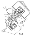
- a slitter device marked 9 in a general way, comprises a series of mutually coaxial discoidal cutters 11 aligned along an axis A (see in particular Fig. 2). Only one cutter can be seen in the drawing, but it should be understood that there are a plurality of cutters along the axis A, sufficient in number to slit the weblike material N into the desired number of strips required for the particular job.
- Each cutter is mounted on a support 13.
- Each support 13 travels along tracks 15 parallel to the axis A and perpendicular to the direction of forward travel of the weblike material N and of the strips S into which it is divided by the slitter device 9. In this way, each support can be moved to the point where the longitudinal slit is to be made in the weblike material N.
- the positioning of each slitter tool 11,13 can be performed in a manner known per se using a positioning device, marked 17 in a general way, and the clamping of the slitter tools in the desired positions can be done in a manner known per se which is not relevant to the present invention.
- the slitter device 9 For each discoidal cutter 11, the slitter device 9 includes a mating cutter 21, each mounted on its own support 23.
- the figures show only one mating cutter 21, but it must be realized that there are a plurality of identical mating cutters along the axis B (parallel to the axis A).
- Each support 23 is positionable along tracks 25 parallel to the axis B.
- the reference 27 is a general indication for a positioning device, which may be of any type and is not relevant for the purposes of the present description, for positioning the mating cutters 21 along the tracks 25.
- the cutters 11 and the mating cutters 21 constitute two series of rotating discoidal slitter tools.
- the account given below referring to the actuation of the mating cutters can also be applied to the actuation of a different type of discoidal slitting tool, e.g. a slitting cutter. If both the tools (cutter and mating cutter) are to be motorized, the solution described for driving the mating cutters 21 can be used for the actuation of the cutters.
- the various mating cutters are all the same as each other and only one of them, together with its support, will be described in detail with reference to Figs. 3 and 4. It is not ruled out that the slitter device may also include mating cutters that differ in configuration and actuation from those whose structure is as illustrated in Figs. 3 3 and 4.
- Each mating cutter 21 has an electric drive motor.
- This motor comprises a stator 31 and a rotor 33.
- the stator 31 is housed in a roughly approximately cylindrical seat 35 made in the body 23A of the mating cutter support 23.
- the seat 35 has a back wall 37 containing a large circular aperture 37A surrounded by an annular ridge 37B.
- Around the circumference of the annular ridge 37B are seats 37C for fastening screws for clamping a spindle 39 on which the rotor 33 is mounted.
- the mounting spindle 39 has one end whose diameter is approximately equal to the diameter of the aperture 37A and is inserted into this aperture.
- the end 39A terminates in a shoulder defined by a fixing flange 39B with threaded holes for the engagement of the fastening screws inserted into the seats 37C of the annular ridge 37B.
- said spindle 39 continues and forms the seat for a bearing 41 on which fits a hollow shaft 43 around which the rotor 33 is formed.
- the number 45 denotes a disk screwed onto the corresponding end of the mounting spindle 39 so as to lock the inner ring of the bearing 41.
- the inner ring is locked by a shoulder 39B formed on the mounting spindle 39.
- the bearing 41 may advantageously be a double-row ball bearing or equivalent means, so that it can also take bending moments and loads parallel to the mounting spindle 39, thus making two bearings unnecessary.
- the hollow shaft 43 extends radially outside the support 23, eventually forming a flange 47, screwed to which, with screws 50, is a ring 49 forming the active portion of the mating cutter 21.
- the ring 49 has a conical annular surface 49A of large aperture which acts in combination with the slitting cutter 11, as indicated in chain line in Figs. 3 and 4.
- the through hole in the hollow shaft 43 is closed by a cover 51 screwed by screws 53 to the flange 47 and forming an abutment to hold the outer ring of the bearing 41 in place.
- the abutment on the opposite side of the outer ring is formed by a collar 43A made in one piece with the hollow shaft 43.
- the construction described above is axially very compact and the total axial dimension D of the mating cutter 21 with the support 23 may even be equal to or less than 50 mm.
- the axial dimension is very small partly because of the fact that the stator (which is one of the largest components) projects on one side into an annular cavity 47X formed in the flange 47 and on the other into a similar annular cavity recessed into the back wall 37 which defines the seat 35.
- This back wall could also be produced in the form of a separate flange which is then fixed in position.
- a hole 61 to take the electric wire is also shown in Fig. 4 .
- Another hole (not shown) can be provided so that air can be blown in under gentle pressure into the seat 35 to prevent dust getting into the motor.
- a labyrinth seal indicated schematically at 63 may be used.
Landscapes
- Life Sciences & Earth Sciences (AREA)
- Forests & Forestry (AREA)
- Engineering & Computer Science (AREA)
- Mechanical Engineering (AREA)
- Winding Of Webs (AREA)
- Replacement Of Web Rolls (AREA)
- Treatment Of Fiber Materials (AREA)
- Perforating, Stamping-Out Or Severing By Means Other Than Cutting (AREA)
- Advancing Webs (AREA)
- Nonmetal Cutting Devices (AREA)
Claims (16)
- Längsschneidvorrichtung zum Unterteilen einer Materialbahn, mit wenigstens einer Reihe von rotierenden, scheibenförmigen Schneidwerkzeugen (21), wobei jedes Werkzeug auf seinem eigenen Halter (23) montiert ist, der mit seinem eigenen Antriebsmotor ausgerüstet ist, welcher einen Stator (31) und einen Rotor (33) aufweist, dadurch gekennzeichnet, dass der Motor innerhalb der Abmessungen des Halters und des Werkzeuges enthalten ist, wobei der Halter einen grob annähernd zylindrischen Sitz (35) aufweist, in welchem der Stator und der Rotor angeordnet sind, wobei der Stator und der Rotor einander umgeben und das Werkzeug (21) koaxial zum Rotor und zum Stator ist.
- Vorrichtung nach Anspruch 1, dadurch gekennzeichnet, dass der Halter (23) einen Körper (23A) aufweist, der den annähernd zylindrischen Sitz (35) im Inneren begrenzt und dass eine Montagespindel (39), die sich in den grob annähernd zylindrischen Sitz (35) erstreckt, auf welcher der Rotor (33) des Motors montiert ist, einstückig mit dem Körper ausgebildet ist.
- Vorrichtung nach Anspruch 2, dadurch gekennzeichnet, dass der Rotor eine Hohlwelle (43) hat, die auf der Montagespindel (39) montiert ist.
- Vorrichtung nach Anspruch 1, 2 oder 3, dadurch gekennzeichnet, dass die Halter (23) entlang einer Positionierspur (25) eingestellt und festgeklemmt werden können.
- Vorrichtung nach Anspruch 3, dadurch gekennzeichnet, dass ein Flansch (27), an welchem das Schneidwerkzeug (21) befestigt ist oder der einen Teil desselben bildet, einstückig mit der Hohlwelle des Rotors ausgebildet ist.
- Vorrichtung nach Anspruch 5, dadurch gekennzeichnet, dass der Flansch einstückig mit der Hohlwelle ausgebildet ist.
- Vorrichtung nach Anspruch 5 oder 6, dadurch gekennzeichnet, dass der Flansch einen ringförmigen Hohlraum (47X) hat, in welchen der Stator (31) des Motors vorsteht.
- Vorrichtung nach Anspruch 5, 6 oder 7, dadurch gekennzeichnet, dass der Flansch ein axiales Paßloch hat und mit einer Abdeckung (51) versehen ist, die dieses Loch abdeckt.
- Vorrichtung nach einem oder mehreren der Ansprüche 1 bis 8, dadurch gekennzeichnet, dass der annähernd zylindrische Sitz eine Rückwand (37) mit einer Ringnut hat, um einen vorstehenden Teil des Stators aufzunehmen.
- Vorrichtung nach einem oder mehrere der Ansprüche 1 bis 9, dadurch gekennzeichnet, dass der grob annähernd zylindrische Sitz eine Rückwand (37) mit einer zentralen Durchgangsöffnung (37A) hat, in die ein Ende (39A) der Montagespindel (39) eingesetzt ist.
- Vorrichtung nach Anspruch 10, dadurch gekennzeichnet, dass die zentrale Durchgangsöffnung (37A) von einer ringförmigen Rippe (37B) mit durchgehenden Sitzen (37C) für Schrauben zum Befestigen der Montagespindel (39) umgeben ist, wobei die Sitze so zugänglich sind, dass die Befestigungsschrauben von der vom Stator (33) entfernten Seite her eingeschraubt werden können.
- Vorrichtung nach Anspruch 10 oder 11, dadurch gekennzeichnet, dass die Montagespindel einen Klemmflansch (39B) hat, mittels welchem die Spindel an der Rückwand des grob annähernd zylindrischen Sitzes geklemmt ist.
- Vorrichtung nach einem oder mehreren der Ansprüche 3 bis 12, dadurch gekennzeichnet, dass die Hohlwelle des Rotors ein einzelnes Lager (41) aufnimmt.
- Vorrichtung nach einem oder mehreren der vorstehenden Ansprüche, dadurch gekennzeichnet, dass die Gesamtaxialabmessung des Halters und des Schneidwerkzeuges gleich oder kleiner als 50 mm ist.
- Vorrichtung nach einem oder mehreren der vorstehenden Ansprüche, dadurch gekennzeichnet, dass diese eine zweite Reihe von rotierenden, scheibenförmigen Schneidwerkzeugen (11) aufweist, wobei die Werkzeuge (11) der zweiten Reihe in Verbindung mit den Werkzeugen (21) der ersten Reihe zusammenwirken.
- Aufwickelvorrichtung zum Erzeugen von Rollen von aufgewickeltem bahnförmigen Material, mit einer Aufwickeleinheit, einem Weg, entlang welchem das bahnförmige Material zu der Aufwickeleinheit geleitet wird und einer Schneidvorrichtung zum Unterteilen des bahnförmigen Materials in eine Anzahl von Streifen, die jeweils eine Rolle des bahnförmigen Materials bilden sollen, dadurch gekennzeichnet, dass die Schneidvorrichtung in Übereinstimmung mit einem oder mehreren der vorstehenden Patentansprüche konstruiert ist.
Priority Applications (5)
| Application Number | Priority Date | Filing Date | Title |
|---|---|---|---|
| AT01830206T ATE304985T1 (de) | 2001-03-26 | 2001-03-26 | Längsschneidvorrichtung zum unterteilen einer materialbahn und umwickler mit solcher vorrichtung |
| DK01830206T DK1245519T3 (da) | 2001-03-26 | 2001-03-26 | Indretning til langsgående opskæring af et kontinuert vævlignende materiale og en oprullemaskine omfattende nævnte indretning |
| EP01830206A EP1245519B1 (de) | 2001-03-26 | 2001-03-26 | Längsschneidvorrichtung zum Unterteilen einer Materialbahn und Umwickler mit solcher Vorrichtung |
| ES01830206T ES2248268T3 (es) | 2001-03-26 | 2001-03-26 | Un dispositivo para el corte longitudinal de un material continuo laminar y una bobinadora que comprende dicho dispositivo. |
| DE60113502T DE60113502T2 (de) | 2001-03-26 | 2001-03-26 | Längsschneidvorrichtung zum Unterteilen einer Materialbahn und Umwickler mit solcher Vorrichtung |
Applications Claiming Priority (1)
| Application Number | Priority Date | Filing Date | Title |
|---|---|---|---|
| EP01830206A EP1245519B1 (de) | 2001-03-26 | 2001-03-26 | Längsschneidvorrichtung zum Unterteilen einer Materialbahn und Umwickler mit solcher Vorrichtung |
Publications (2)
| Publication Number | Publication Date |
|---|---|
| EP1245519A1 EP1245519A1 (de) | 2002-10-02 |
| EP1245519B1 true EP1245519B1 (de) | 2005-09-21 |
Family
ID=8184461
Family Applications (1)
| Application Number | Title | Priority Date | Filing Date |
|---|---|---|---|
| EP01830206A Expired - Lifetime EP1245519B1 (de) | 2001-03-26 | 2001-03-26 | Längsschneidvorrichtung zum Unterteilen einer Materialbahn und Umwickler mit solcher Vorrichtung |
Country Status (5)
| Country | Link |
|---|---|
| EP (1) | EP1245519B1 (de) |
| AT (1) | ATE304985T1 (de) |
| DE (1) | DE60113502T2 (de) |
| DK (1) | DK1245519T3 (de) |
| ES (1) | ES2248268T3 (de) |
Families Citing this family (3)
| Publication number | Priority date | Publication date | Assignee | Title |
|---|---|---|---|---|
| IT201800009236A1 (it) | 2018-10-08 | 2020-04-08 | A Celli Paper Spa | Macchina ribobinatrice e metodo per il controllo della velocita’ dei motori in una macchina ribobinatrice |
| IT201800009482A1 (it) | 2018-10-16 | 2020-04-16 | Italia Tech Alliance Srl | Macchina di avvolgimento con dispositivi per il calcolo del coefficiente di poisson e metodo |
| MX2021004341A (es) | 2018-10-16 | 2021-08-19 | Italia Tech Alliance S R L | Bobinadora con un sistema de evaluacion del material de entramado que se procesa y metodo. |
Family Cites Families (2)
| Publication number | Priority date | Publication date | Assignee | Title |
|---|---|---|---|---|
| US4520704A (en) * | 1983-08-05 | 1985-06-04 | Beloit Corporation | Motor driven slitter of narrow configuration |
| JPH0725055B2 (ja) * | 1991-12-17 | 1995-03-22 | 明産株式会社 | 極狭巾のシヤーカットが可能なスリッタードライブユニット |
-
2001
- 2001-03-26 EP EP01830206A patent/EP1245519B1/de not_active Expired - Lifetime
- 2001-03-26 DE DE60113502T patent/DE60113502T2/de not_active Expired - Lifetime
- 2001-03-26 DK DK01830206T patent/DK1245519T3/da active
- 2001-03-26 AT AT01830206T patent/ATE304985T1/de not_active IP Right Cessation
- 2001-03-26 ES ES01830206T patent/ES2248268T3/es not_active Expired - Lifetime
Also Published As
| Publication number | Publication date |
|---|---|
| DE60113502D1 (de) | 2006-02-02 |
| DK1245519T3 (da) | 2006-02-06 |
| DE60113502T2 (de) | 2006-06-29 |
| ATE304985T1 (de) | 2005-10-15 |
| ES2248268T3 (es) | 2006-03-16 |
| EP1245519A1 (de) | 2002-10-02 |
Similar Documents
| Publication | Publication Date | Title |
|---|---|---|
| JP2022527948A (ja) | 柔軟なラインのための小型巻取り装置 | |
| US20110042505A1 (en) | Reel changer having a holder for supporting a material reel with a winding sleeve | |
| EP1245519B1 (de) | Längsschneidvorrichtung zum Unterteilen einer Materialbahn und Umwickler mit solcher Vorrichtung | |
| KR101868994B1 (ko) | 테이프의 커팅 길이 조절이 가능한 디스펜서 | |
| US4646603A (en) | Lower cutter of an apparatus for longitudinally slitting a web | |
| KR102188680B1 (ko) | 고성능 슬리터 | |
| JP3076247B2 (ja) | スリッター | |
| JP6612641B2 (ja) | バイアス織物製造装置 | |
| EP1494947B1 (de) | Umwickelarm für plastikfolienlängsschneidvorrichtung | |
| JPS62130948A (ja) | 巻取機におけるスピンドル駆動装置 | |
| JP2762258B2 (ja) | 弾性糸の安定巻き戻し供給装置 | |
| WO2022137111A1 (en) | Method for making rolls of flexible tape, system for carrying out such method and unwinder - applicator of said rolls of flexible tape. | |
| JP3710824B2 (ja) | さく岩機に可撓性要素を誘導するための装置とホースリール構造 | |
| WO1999002442A1 (en) | An improved shaft for supporting cut sections of a reel in a cutting and winding machine | |
| US5632455A (en) | Apparatus for working on sheet material and having friction hub | |
| JP4194510B2 (ja) | 巻取装置 | |
| JP2006043850A (ja) | カセット式ワイヤ供給装置 | |
| JP3379252B2 (ja) | スリッタのタッチロール支持装置 | |
| JP3323643B2 (ja) | アンコイラ | |
| JP3113638B2 (ja) | 巻線装置 | |
| JPH05343250A (ja) | トロイダルコイル巻線機 | |
| KR200252511Y1 (ko) | 직물원단 재단기 | |
| IT1319321B1 (it) | Macchina ribobinatrice periferica e metodo per la produzione di logsdi materiali in foglio | |
| JPH0615936Y2 (ja) | 巻取りリール | |
| CN209988828U (zh) | 一种光学膜分条机 |
Legal Events
| Date | Code | Title | Description |
|---|---|---|---|
| PUAI | Public reference made under article 153(3) epc to a published international application that has entered the european phase |
Free format text: ORIGINAL CODE: 0009012 |
|
| 17P | Request for examination filed |
Effective date: 20020308 |
|
| AK | Designated contracting states |
Kind code of ref document: A1 Designated state(s): AT BE CH CY DE DK ES FI FR GB GR IE IT LI LU MC NL PT SE TR |
|
| AX | Request for extension of the european patent |
Free format text: AL;LT;LV;MK;RO;SI |
|
| AKX | Designation fees paid |
Designated state(s): AT BE CH CY DE DK ES FI FR GB GR IE IT LI LU MC NL PT SE TR |
|
| RAP1 | Party data changed (applicant data changed or rights of an application transferred) |
Owner name: A. CELLI NONWOVENS S.P.A. |
|
| 17Q | First examination report despatched |
Effective date: 20040128 |
|
| GRAP | Despatch of communication of intention to grant a patent |
Free format text: ORIGINAL CODE: EPIDOSNIGR1 |
|
| GRAS | Grant fee paid |
Free format text: ORIGINAL CODE: EPIDOSNIGR3 |
|
| GRAA | (expected) grant |
Free format text: ORIGINAL CODE: 0009210 |
|
| AK | Designated contracting states |
Kind code of ref document: B1 Designated state(s): AT BE CH CY DE DK ES FI FR GB GR IE IT LI LU MC NL PT SE TR |
|
| REG | Reference to a national code |
Ref country code: GB Ref legal event code: FG4D |
|
| REG | Reference to a national code |
Ref country code: CH Ref legal event code: EP Ref country code: CH Ref legal event code: NV Representative=s name: KIRKER & CIE SA |
|
| REG | Reference to a national code |
Ref country code: IE Ref legal event code: FG4D |
|
| REF | Corresponds to: |
Ref document number: 60113502 Country of ref document: DE Date of ref document: 20051027 Kind code of ref document: P |
|
| REG | Reference to a national code |
Ref country code: SE Ref legal event code: TRGR |
|
| REG | Reference to a national code |
Ref country code: GR Ref legal event code: EP Ref document number: 20050403535 Country of ref document: GR |
|
| REF | Corresponds to: |
Ref document number: 60113502 Country of ref document: DE Date of ref document: 20060202 Kind code of ref document: P |
|
| REG | Reference to a national code |
Ref country code: DK Ref legal event code: T3 |
|
| REG | Reference to a national code |
Ref country code: ES Ref legal event code: FG2A Ref document number: 2248268 Country of ref document: ES Kind code of ref document: T3 |
|
| PG25 | Lapsed in a contracting state [announced via postgrant information from national office to epo] |
Ref country code: MC Free format text: LAPSE BECAUSE OF NON-PAYMENT OF DUE FEES Effective date: 20060331 Ref country code: LU Free format text: LAPSE BECAUSE OF NON-PAYMENT OF DUE FEES Effective date: 20060331 |
|
| ET | Fr: translation filed | ||
| PLBE | No opposition filed within time limit |
Free format text: ORIGINAL CODE: 0009261 |
|
| STAA | Information on the status of an ep patent application or granted ep patent |
Free format text: STATUS: NO OPPOSITION FILED WITHIN TIME LIMIT |
|
| 26N | No opposition filed |
Effective date: 20060622 |
|
| PGFP | Annual fee paid to national office [announced via postgrant information from national office to epo] |
Ref country code: FI Payment date: 20080327 Year of fee payment: 8 Ref country code: GB Payment date: 20080326 Year of fee payment: 8 Ref country code: PT Payment date: 20080305 Year of fee payment: 8 |
|
| PGFP | Annual fee paid to national office [announced via postgrant information from national office to epo] |
Ref country code: AT Payment date: 20080327 Year of fee payment: 8 |
|
| PGFP | Annual fee paid to national office [announced via postgrant information from national office to epo] |
Ref country code: CH Payment date: 20080328 Year of fee payment: 8 |
|
| PGFP | Annual fee paid to national office [announced via postgrant information from national office to epo] |
Ref country code: BE Payment date: 20080325 Year of fee payment: 8 |
|
| PG25 | Lapsed in a contracting state [announced via postgrant information from national office to epo] |
Ref country code: CY Free format text: LAPSE BECAUSE OF FAILURE TO SUBMIT A TRANSLATION OF THE DESCRIPTION OR TO PAY THE FEE WITHIN THE PRESCRIBED TIME-LIMIT Effective date: 20050921 |
|
| BERE | Be: lapsed |
Owner name: A. *CELLI NONWOVENS S.P.A. Effective date: 20090331 |
|
| REG | Reference to a national code |
Ref country code: PT Ref legal event code: MM4A Free format text: LAPSE DUE TO NON-PAYMENT OF FEES Effective date: 20090928 |
|
| PG25 | Lapsed in a contracting state [announced via postgrant information from national office to epo] |
Ref country code: AT Free format text: LAPSE BECAUSE OF NON-PAYMENT OF DUE FEES Effective date: 20090326 Ref country code: PT Free format text: LAPSE BECAUSE OF NON-PAYMENT OF DUE FEES Effective date: 20090928 Ref country code: FI Free format text: LAPSE BECAUSE OF NON-PAYMENT OF DUE FEES Effective date: 20090326 |
|
| REG | Reference to a national code |
Ref country code: CH Ref legal event code: PL |
|
| GBPC | Gb: european patent ceased through non-payment of renewal fee |
Effective date: 20090326 |
|
| PG25 | Lapsed in a contracting state [announced via postgrant information from national office to epo] |
Ref country code: CH Free format text: LAPSE BECAUSE OF NON-PAYMENT OF DUE FEES Effective date: 20090331 Ref country code: LI Free format text: LAPSE BECAUSE OF NON-PAYMENT OF DUE FEES Effective date: 20090331 |
|
| PG25 | Lapsed in a contracting state [announced via postgrant information from national office to epo] |
Ref country code: BE Free format text: LAPSE BECAUSE OF NON-PAYMENT OF DUE FEES Effective date: 20090331 |
|
| PG25 | Lapsed in a contracting state [announced via postgrant information from national office to epo] |
Ref country code: GB Free format text: LAPSE BECAUSE OF NON-PAYMENT OF DUE FEES Effective date: 20090326 |
|
| REG | Reference to a national code |
Ref country code: FR Ref legal event code: PLFP Year of fee payment: 15 |
|
| REG | Reference to a national code |
Ref country code: FR Ref legal event code: PLFP Year of fee payment: 16 |
|
| REG | Reference to a national code |
Ref country code: FR Ref legal event code: PLFP Year of fee payment: 17 |
|
| REG | Reference to a national code |
Ref country code: FR Ref legal event code: PLFP Year of fee payment: 18 |
|
| PGFP | Annual fee paid to national office [announced via postgrant information from national office to epo] |
Ref country code: DK Payment date: 20200214 Year of fee payment: 20 Ref country code: IT Payment date: 20200225 Year of fee payment: 20 Ref country code: IE Payment date: 20200127 Year of fee payment: 20 Ref country code: NL Payment date: 20200218 Year of fee payment: 20 Ref country code: SE Payment date: 20200317 Year of fee payment: 20 Ref country code: GR Payment date: 20200130 Year of fee payment: 20 |
|
| PGFP | Annual fee paid to national office [announced via postgrant information from national office to epo] |
Ref country code: TR Payment date: 20200325 Year of fee payment: 20 Ref country code: FR Payment date: 20200129 Year of fee payment: 20 |
|
| PGFP | Annual fee paid to national office [announced via postgrant information from national office to epo] |
Ref country code: DE Payment date: 20200525 Year of fee payment: 20 Ref country code: ES Payment date: 20200415 Year of fee payment: 20 |
|
| REG | Reference to a national code |
Ref country code: DE Ref legal event code: R071 Ref document number: 60113502 Country of ref document: DE |
|
| REG | Reference to a national code |
Ref country code: DK Ref legal event code: EUP Expiry date: 20210326 |
|
| REG | Reference to a national code |
Ref country code: NL Ref legal event code: MK Effective date: 20210325 |
|
| REG | Reference to a national code |
Ref country code: IE Ref legal event code: MK9A |
|
| PG25 | Lapsed in a contracting state [announced via postgrant information from national office to epo] |
Ref country code: IE Free format text: LAPSE BECAUSE OF EXPIRATION OF PROTECTION Effective date: 20210326 |
|
| REG | Reference to a national code |
Ref country code: SE Ref legal event code: EUG |
|
| REG | Reference to a national code |
Ref country code: ES Ref legal event code: FD2A Effective date: 20211102 |
|
| PG25 | Lapsed in a contracting state [announced via postgrant information from national office to epo] |
Ref country code: ES Free format text: LAPSE BECAUSE OF EXPIRATION OF PROTECTION Effective date: 20210327 |