EP1245757A2 - Tour d'escalier pour gros-oeuvre - Google Patents
Tour d'escalier pour gros-oeuvre Download PDFInfo
- Publication number
- EP1245757A2 EP1245757A2 EP02003707A EP02003707A EP1245757A2 EP 1245757 A2 EP1245757 A2 EP 1245757A2 EP 02003707 A EP02003707 A EP 02003707A EP 02003707 A EP02003707 A EP 02003707A EP 1245757 A2 EP1245757 A2 EP 1245757A2
- Authority
- EP
- European Patent Office
- Prior art keywords
- stair
- shell
- tower according
- staircase
- vertical
- Prior art date
- Legal status (The legal status is an assumption and is not a legal conclusion. Google has not performed a legal analysis and makes no representation as to the accuracy of the status listed.)
- Granted
Links
Images



Classifications
-
- E—FIXED CONSTRUCTIONS
- E04—BUILDING
- E04G—SCAFFOLDING; FORMS; SHUTTERING; BUILDING IMPLEMENTS OR AIDS, OR THEIR USE; HANDLING BUILDING MATERIALS ON THE SITE; REPAIRING, BREAKING-UP OR OTHER WORK ON EXISTING BUILDINGS
- E04G27/00—Temporary arrangements for giving access from one level to another for men or vehicles, e.g. steps, ramps
Definitions
- the present invention relates to a structural staircase tower.
- Such stair towers become one in the unfinished state
- the building was temporarily assembled so that the individual floors are easily accessible. They should be quick and easy can be assembled or disassembled and at the same time the security requirements regarding the Fulfill stairs.
- the usual floor height in residential construction is approx. 250 to 300 cm (centimeters).
- structural stairs are common Wooden stairs are used, which are sent to the respective site Conditions to be adjusted.
- the present invention has the technical problem or based on the task of one Shell stair tower to indicate the extremely simple and fast can be assembled or disassembled by the on climbing stairs to meet safety requirements fulfilled and also economical can be produced.
- the invention also has the technical problem or the task, a crossbar for to specify a shell stair tower using Standard scaffolding components compensate for the different storey heights or scaffold system heights on the one hand in scaffolding according to the used Standard scaffolding and, on the other hand, simpler in residential construction Way to enable.
- the invention Crossbar is given by the features of claim 17.
- Advantageous refinements and developments are Subject matter of claim 17 directly or indirectly dependent claims.
- the invention also has the technical problem or the task, a cover profile bar specify that in a simple manner in a Structural stair tower can be used and the Access security increased.
- the cover profile rod according to the invention is for one Structural staircase tower by the characteristics of the independent Claim 20 given.
- advantageous embodiments and Developments are the subject of claim 20 directly or indirectly dependent claims.
- the shell stair tower according to the invention is accordingly with following components originating from a standard framework built up: at least four in the endpoints of one vertical stalks arranged in orthogonal quadrilaterals with in a circumferential rosette connected with a longitudinal grid Recesses, the crossbars connecting the vertical stems, the Longitudinal bars connecting vertical stems, diagonal bracing, which simultaneously form a handrail, the Crossbars, longitudinal bars and diagonals in their respective End area a wedge head with a gap and a wedge have the wedge head on the respective rosette of the Slipped on the vertical stem and by means of the foldable Keils is detachably connected to the rosette, and following other components: stair equipment, the steps have a step height, which is half the longitudinal grid dimension of the rosettes Corresponds to vertical stems and diametrically opposite Crossbars are connected.
- a particularly advantageous embodiment is distinguished in that the grid size is 40 to 60 cm (centimeters), in particular 50 cm (centimeters).
- One in The usual storey height can easily be built implement that preferably two per floor Stair facilities are used, including Entry and exit steps a total of six steps include.
- the security of the structural staircase tower is thereby in advantageously increased by centering between oppositely arranged stair facilities continuous vertical rod is arranged for the Person climbing the stair tower has an additional hand rest represents.
- the vertical rod is preferably designed as a tubular profile.
- a particularly preferred embodiment that the Access security increased further, is characterized by that in the area between the exit step and the Entry level of neighboring staircase facilities Cover profile bar is arranged on a crossbar and is connected to the vertical rod and the between the Exit step and entry step covers existing gap, the cover profile rod preferably as a rectangle or Square tube profile is formed.
- the one easy adaptation to different storey heights according to the building site is characterized by that another additional part is used, namely at least one cross bar, the underside at least one has additional joist to which the staircase device is connected and that at a distance of half Longitudinal grid dimension and / or a third of the distance Longitudinal grid dimension to the crossbar is available.
- This beam is preferred as a U-profile open at the top trained, the beam in particular a Length that is essentially the width of the Stair device corresponds.
- one from the Scaffolding implements the tried and tested connection to the crossbars is characterized by the fact that the staircase in the Area of entry level or exit level Hook-in claws for hanging on the u-profile Crossbar or the beam has.
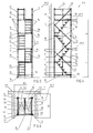
- FIG. 1 to 3 is a first embodiment of a shell stair tower 10.1 shown schematically.
- the Shell stair tower 10.1 essentially has scaffolding standard components based on the well-known Layher all-round scaffolding system come.
- the shell stair tower has 10.1 a rectangular plan.
- In the corner points are stacked vertical stems 12 arranged in Grid sizes from 1 to 4 m (meters) in 50 cm increments (Centimeter increments) are available.
- In Longitudinal direction of the vertical stems 12 are in a grid dimension R on each vertical stem 12 with surrounding rosettes 14 Recesses exist on which further scaffolding components can be connected.
- the rosettes 14 are in the Longitudinal grid dimension R available, that in the exemplary embodiment each is 50 cm (centimeters).
- each two crossbars 16 connected to rosettes 14, which as U-profiles open at the top are formed.
- rosettes 14 On the two Side edges are at the level of the crossbars 16 longitudinal bars 18th connected, which are designed as round tubes.
- diagonals 20 are connected, on the one hand serve for stiffening and on the other hand in the existing Shell stair tower implement a handrail function.
- connection of the cross bar 16, longitudinal bar 18 and Diagonals 20 take place over the known as such Wedge lock technology and is for example in the Publication "Installation instructions for the Layher all-round scaffolding" described in detail.
- the bars 16, 18 and Diagonals 20 each have a wedge head in their end region Gap that can be pushed onto the rosette 14, the component itself by driving in a wedge is releasably locked to the vertical handle.
- Stair devices 30 are present, which are shown in FIGS and 18 are described in more detail.
- the shell stair tower 10.1 is in a stair hole 46 the dimensions B1 and B2 of a shell building 48 arranged, the Floor slabs 49.1, 49.2.
- the floor height G is indicated by the reference symbol G.
- the system vertical dimensions of the Vertical sticks 12 in 50 cm increments (centimeter increments) are designed. These are usually with the Storey heights G, for example approx. 270 cm (centimeters) amount, not compatible.
- FIGS. 17 and 18 30 Such a staircase device is shown in FIGS. 17 and 18 30 shown in more detail.
- the staircase device 30 is designed as a framework. She owns her Side edge areas two inclined support profiles 56, those in the upper or lower end area horizontally are formed, on these horizontal areas exit level 44 or entry level 42 is arranged. Between entry level 42 and Exit step 44 are on triangular bracket beams 58 Treads 32 stored.
- the height distance R / 2 between steps 42, 32, 44 is half of the longitudinal grid dimension R.
- the front end area is in each case transverse to the support profiles 56 Cross section 60 connected.
- the stairway device 30 has a width B which is so is formed that on a crossbar 16 at a opposite stairs two and in the same direction Stairs can be hung up a staircase means here that the system dimensions of the Standard cross bar 16.
- the in Figure 2 second and fourth stair device 30 inclined to the right is also suspended in crossbar 16 in area A. and in the area of its exit step 44 to a cross bar 16 connected, which in turn is connected to a standard rosette 14 connected.
- the Entry level 42, exit level 44 and the Console unit 50 are located at a height that the Floor height G of the first floor corresponds to 49.1.
- the second floor 49.2 is basically the same connected another two oppositely arranged Stair facilities 30 reached, due to the given system dimensions, the upper exit step 44 and Console unit 50 one step lower than that Floor height G of the second floor 49.2 is arranged.
- stair tower in the middle of the construction stair tower is from above running continuously downwards between the opposing ones Stair devices 30 connected to a vertical rod 34, which serves as a hand support and further increases safety on foot elevated.
- This vertical rod 34 can in the whole Inspection process to be taken, so that an inside Manual guidance as for a spiral staircase.
- This cover profile rod 36 consists of an in the embodiment formed as a rectangular tube, the one Width BS has the width of the between inclusion Exit stage 42, 44 existing gap in the Essentially corresponds.
- the cover profile rod In its outside end area the cover profile rod has a U-profile unit pointing downwards 38, which has such a large internal dimension has that over the U-profile of the transom 16 can be hung.
- a pipe half coupling 40 is connected so that the profile rod 36 easily to the vertical rod 34 is attachable.
- the first, lowest stair device 30 is on one Crossbar connected, which in turn has a Pitch R / 2 offset from standard rosette 14 Existing clamped rosette is connected.
- this staircase device 30 in the The area of entrance step 42 is this staircase device 30 connected to a cross bar 16, the one Standard rosette 14 connected.
- the next one is offset in the transverse direction Stair device 30 in the area of its entrance step 42 the same crossbar 16 connected.
- Exit level 44 this staircase device 30 is in turn connected to one Crossbar 16 connected, which in turn is releasable 14 connected rosette between two standard rosettes connected.
- the exit step 44 is thus located the second staircase 30 at the level of the first Storey 49.1.
- the third connected at this height Staircase device 30 is in turn in the area Exit stage 44 connected to a cross bar 16, the again on standard rosettes 14 connected.
- the fourth staircase device 30 is in their entrance area offset by the pitch R / 2 a crossbar 16 connected, which in turn via between the grid dimensions in the middle between the grid dimensions the standard rosette 14 arranged detachable rosette connected.
- the area of Exit step 44 of the fourth staircase 30 at height of the second floor 49.2 and can thus be connected to one Crossbar 16 are shot, which in turn itself over Standard rosette 14 is connected.
- FIGS. 7 to 9 show a third exemplary embodiment of a shell stair tower 10.3 shown as parallel staircase is formed.
- opposing staircase 30 sets the Unfinished stair tower 10.3 consisting of two connected in series "Scaffolding fields" together, with a total of six scaffolding stems 12 are used.
- the stair facilities 30 themselves are arranged one behind the other, so with two stair facilities 30 a floor height G is bridged.
- the first lower staircase is on a cross bar 16 connected, which in turn is offset by the pitch R / 2 to the standard rosette 14 is available.
- the lower staircase device 30 In the field of Exit step 44 is the lower staircase device 30 a crossbar 16 connected by default correspondingly to an existing one in pitch R. Standard rosette 14 is connected.
- the same Crossbar 16 is the area of entry level 42 of the second parallel staircase devices 30 connected, the exit step area in turn a cross bar 16 is connected, the grid dimension around R / 2 offset from a standard rosette 14 on the Vertical stem 12 connected via the detachable rosette 15 is.
- the exit stage 44 of the second is thus located Staircase at the level of the first floor 49.1.
- the third staircase device 30 is in turn one Cross bar 16 connected to a standard rosette 14th is connected in the area of its entry level 42, wherein here already a grid-like offset in the size of R / 2 to floor height G of the first floor 49.1 is present.
- the exit area of the third staircase device 30 is in turn connected to a cross bar 16 which around the Pitch R / 2 releasably to the vertical handle 12 clamped rosette 15 is connected.
- the same Cross member 16 is finally the fourth synchronous Stair device 30 in the area of its entrance step 42 connected, which in turn in the area of their exit level 44 is connected on the upper side to a cross bar 16 which is connected to a standard rosette 14, whereby then the exit step 44 at the level G of the second floor 49.2 is located.
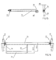
- FIGS. 10 to 12 of a shell stair tower 10.4 shown by its the basic structure is the same as the structural staircase tower 10.2, where, however, on the use of detachable between the Standard rosettes 14 connected rosettes is dispensed with and a specially designed cross bar 24 is used, which is shown in Figure 16.
- the Crossbar 24 according to Figure 16 corresponds to that Crossbar 16 according to the standard scaffolding part its end area existing wedge heads 22 for connection the standard rosette 14.
- the beam 26 is around the R / 2 grid offset downwards to the upper one Crossbar profile available.
- the width BU of the beam 26 is dimensioned slightly larger than the width B one Stair device 30, so that this easily over their Hooking claws 28 are hooked into the beam 26 can.
- a vertical rod 34 is centered on the outside connected, particularly when entering and exiting the additional stopping facility increases the security of the walk.
- cross bar 24 is the fourth embodiment of the structural staircase tower 10.4 according to FIGS. 10 to 12 formed.
- the bottom stair device 30 is in the Area of their entry level 42 to a standard cross bar 16 connected.
- the area of their exit step 44 is in suspended the beam 26 of the cross bar 24.
- the thing about it subsequent second staircase device 30 is in her Area of entry level 42 again in the upper profile the crossbar 24 hooked.
- the area of Exit step 44 of the second staircase device 30 again hung in the beam 26 of a cross bar 24.
- the arrangement of the third and fourth is corresponding Stairway facility 30.
- the unfinished stair tower according to the invention With the unfinished stair tower according to the invention, it is under A variety of standard scaffolding components can be used, using only a few additional components self-supporting structural staircase towers economical use the different grid dimensions of the Easily balance scaffolding and floor heights, and to the existing stair hole dimensions of the Shell structure are customizable.
Landscapes
- Engineering & Computer Science (AREA)
- Architecture (AREA)
- Mechanical Engineering (AREA)
- Civil Engineering (AREA)
- Structural Engineering (AREA)
- Steps, Ramps, And Handrails (AREA)
- Buildings Adapted To Withstand Abnormal External Influences (AREA)
- Types And Forms Of Lifts (AREA)
Applications Claiming Priority (2)
| Application Number | Priority Date | Filing Date | Title |
|---|---|---|---|
| DE20105346U DE20105346U1 (de) | 2001-03-26 | 2001-03-26 | Rohbautreppenturm |
| DE20105346U | 2001-03-26 |
Publications (3)
| Publication Number | Publication Date |
|---|---|
| EP1245757A2 true EP1245757A2 (fr) | 2002-10-02 |
| EP1245757A3 EP1245757A3 (fr) | 2003-12-03 |
| EP1245757B1 EP1245757B1 (fr) | 2008-05-28 |
Family
ID=7954935
Family Applications (1)
| Application Number | Title | Priority Date | Filing Date |
|---|---|---|---|
| EP02003707A Expired - Lifetime EP1245757B1 (fr) | 2001-03-26 | 2002-02-19 | Tour d'escalier pour gros-oeuvre |
Country Status (3)
| Country | Link |
|---|---|
| EP (1) | EP1245757B1 (fr) |
| AT (1) | ATE397133T1 (fr) |
| DE (2) | DE20105346U1 (fr) |
Families Citing this family (2)
| Publication number | Priority date | Publication date | Assignee | Title |
|---|---|---|---|---|
| FR2914671B1 (fr) * | 2007-04-06 | 2012-04-13 | Espace Btp | Tour d'acces a montage en securite |
| DE102012213593A1 (de) | 2012-08-01 | 2014-02-06 | Wilhelm Layher Verwaltungs-Gmbh | Modulartig aufgebauter Treppengerüstturm und Treppengerüstmodul |
Family Cites Families (2)
| Publication number | Priority date | Publication date | Assignee | Title |
|---|---|---|---|---|
| DE8707755U1 (de) * | 1987-05-30 | 1988-09-29 | Langer, geb. Layher, Ruth, 7129 Güglingen | Aufstiegseinrichtung für Gerüste mit wenigstens einer Treppe |
| DE29815450U1 (de) * | 1998-08-28 | 1998-12-10 | Wilhelm Layher Vermögensverwaltungs-GmbH, 74363 Güglingen | Querriegel für ein Gerüst |
-
2001
- 2001-03-26 DE DE20105346U patent/DE20105346U1/de not_active Expired - Lifetime
-
2002
- 2002-02-19 AT AT02003707T patent/ATE397133T1/de active
- 2002-02-19 DE DE50212307T patent/DE50212307D1/de not_active Expired - Lifetime
- 2002-02-19 EP EP02003707A patent/EP1245757B1/fr not_active Expired - Lifetime
Also Published As
| Publication number | Publication date |
|---|---|
| DE50212307D1 (de) | 2008-07-10 |
| ATE397133T1 (de) | 2008-06-15 |
| EP1245757B1 (fr) | 2008-05-28 |
| DE20105346U1 (de) | 2001-05-23 |
| EP1245757A3 (fr) | 2003-12-03 |
Similar Documents
| Publication | Publication Date | Title |
|---|---|---|
| EP2411598B1 (fr) | Échafaudage et procédé de montage ou de démontage d'un tel échafaudage | |
| DE19655284B4 (de) | Zerlegbares Fassadengerüst | |
| EP2692964B1 (fr) | Tour de cage d'escalier conçue de façon modulaire et module de cage d'escalier | |
| EP1571275A2 (fr) | Dispositif pour le montage d'un garde-corps provisoire d'échafaudage | |
| EP4538481A1 (fr) | Dispositif pour la fixation de protections contre les chutes à des échafaudages | |
| DE3519718C2 (de) | Tragkonstruktion für Tribünen | |
| DE19651901C2 (de) | Sicherheitsschutzgeländerelement, insbesondere für in verschiedenen Richtungen verlaufende Gerüstbauten | |
| EP3306010A1 (fr) | Échafaudage de travail et/ou de protection et procédé d'installation de celui-ci | |
| EP3650616B1 (fr) | Toit de protection contre les intempéries de textile tendu pourvu de bordure d'appui sur le textile | |
| DE820963C (de) | Baugeruest mit aus Rohren bestehenden Staendern | |
| DE10254033A1 (de) | Gerüstboden und Gerüst, Podium oder Tribüne mit einem derartigen Gerüstboden | |
| EP4599138B1 (fr) | Échafaudage, en particulier échafaudage mobile | |
| EP1245757A2 (fr) | Tour d'escalier pour gros-oeuvre | |
| DE29808393U1 (de) | Vorrichtung zum Sichern von neu aufgebauten Ebenen von Baugerüsten gegen Absturzgefahr | |
| EP4392631A1 (fr) | Montant d'échafaudage destiné à être monté verticalement dans une partie d'échafaudage | |
| DE10006094C2 (de) | Gerüsttreppensystem | |
| EP2096235B1 (fr) | Garde-corps à console frontale | |
| DE102022114668B4 (de) | Bewehrungsvorrichtung | |
| DE102019114913A1 (de) | Montageadapter, Sicherheitsgeländer, Bausatz für ein Baugerüst sowie Baugerüst und Verfahren hierfür | |
| DE19614819A1 (de) | Spielturm für Spielplätze | |
| DE2909322C2 (de) | Als Bautreppe verwendbares Treppengerüst | |
| DE10144217A1 (de) | Pfosten für ein Absturzsicherungsgeländer | |
| DE202022105807U1 (de) | Treppenwange | |
| DE102024104509A1 (de) | Stützen-Kopplungsadapter für eine Stützen-Baugruppe | |
| DE102009000936A1 (de) | Schwerlast- und Fluchttreppe für Fassadengerüste |
Legal Events
| Date | Code | Title | Description |
|---|---|---|---|
| PUAI | Public reference made under article 153(3) epc to a published international application that has entered the european phase |
Free format text: ORIGINAL CODE: 0009012 |
|
| AK | Designated contracting states |
Kind code of ref document: A2 Designated state(s): AT BE CH CY DE DK ES FI FR GB GR IE IT LI LU MC NL PT SE TR |
|
| AX | Request for extension of the european patent |
Free format text: AL;LT;LV;MK;RO;SI |
|
| PUAL | Search report despatched |
Free format text: ORIGINAL CODE: 0009013 |
|
| AK | Designated contracting states |
Kind code of ref document: A3 Designated state(s): AT BE CH CY DE DK ES FI FR GB GR IE IT LI LU MC NL PT SE TR |
|
| AX | Request for extension of the european patent |
Extension state: AL LT LV MK RO SI |
|
| RIC1 | Information provided on ipc code assigned before grant |
Ipc: 7E 04G 1/26 B Ipc: 7E 04G 27/00 A |
|
| 17P | Request for examination filed |
Effective date: 20040415 |
|
| AKX | Designation fees paid |
Designated state(s): AT DE |
|
| RAP1 | Party data changed (applicant data changed or rights of an application transferred) |
Owner name: WILHELM LAYHER VERWALTUNGS-GMBH |
|
| 17Q | First examination report despatched |
Effective date: 20070307 |
|
| GRAP | Despatch of communication of intention to grant a patent |
Free format text: ORIGINAL CODE: EPIDOSNIGR1 |
|
| RIC1 | Information provided on ipc code assigned before grant |
Ipc: E04G 27/00 20060101AFI20071219BHEP Ipc: E04G 1/36 20060101ALI20071219BHEP |
|
| GRAS | Grant fee paid |
Free format text: ORIGINAL CODE: EPIDOSNIGR3 |
|
| GRAA | (expected) grant |
Free format text: ORIGINAL CODE: 0009210 |
|
| AK | Designated contracting states |
Kind code of ref document: B1 Designated state(s): AT DE |
|
| REF | Corresponds to: |
Ref document number: 50212307 Country of ref document: DE Date of ref document: 20080710 Kind code of ref document: P |
|
| PLBE | No opposition filed within time limit |
Free format text: ORIGINAL CODE: 0009261 |
|
| STAA | Information on the status of an ep patent application or granted ep patent |
Free format text: STATUS: NO OPPOSITION FILED WITHIN TIME LIMIT |
|
| 26N | No opposition filed |
Effective date: 20090303 |
|
| PGFP | Annual fee paid to national office [announced via postgrant information from national office to epo] |
Ref country code: AT Payment date: 20210216 Year of fee payment: 20 Ref country code: DE Payment date: 20210223 Year of fee payment: 20 |
|
| REG | Reference to a national code |
Ref country code: DE Ref legal event code: R071 Ref document number: 50212307 Country of ref document: DE |
|
| REG | Reference to a national code |
Ref country code: AT Ref legal event code: MK07 Ref document number: 397133 Country of ref document: AT Kind code of ref document: T Effective date: 20220219 |