EP1245768A2 - Têtière d'une crémone pour fenêtres, portes ou similaires et crémone avec une telle têtière - Google Patents
Têtière d'une crémone pour fenêtres, portes ou similaires et crémone avec une telle têtière Download PDFInfo
- Publication number
- EP1245768A2 EP1245768A2 EP02003486A EP02003486A EP1245768A2 EP 1245768 A2 EP1245768 A2 EP 1245768A2 EP 02003486 A EP02003486 A EP 02003486A EP 02003486 A EP02003486 A EP 02003486A EP 1245768 A2 EP1245768 A2 EP 1245768A2
- Authority
- EP
- European Patent Office
- Prior art keywords
- cover plate
- actuating element
- transition
- covering
- face plate
- Prior art date
- Legal status (The legal status is an assumption and is not a legal conclusion. Google has not performed a legal analysis and makes no representation as to the accuracy of the status listed.)
- Withdrawn
Links
- 230000007704 transition Effects 0.000 claims description 31
- 239000011324 bead Substances 0.000 claims description 4
- 239000002184 metal Substances 0.000 claims description 4
- 238000006073 displacement reaction Methods 0.000 claims 1
- 239000000463 material Substances 0.000 description 4
- 229910000831 Steel Inorganic materials 0.000 description 2
- 238000007664 blowing Methods 0.000 description 2
- 238000004140 cleaning Methods 0.000 description 2
- 230000004048 modification Effects 0.000 description 2
- 238000012986 modification Methods 0.000 description 2
- 239000010959 steel Substances 0.000 description 2
- 238000005452 bending Methods 0.000 description 1
- 230000005540 biological transmission Effects 0.000 description 1
- 238000005520 cutting process Methods 0.000 description 1
- 230000006378 damage Effects 0.000 description 1
- 238000005553 drilling Methods 0.000 description 1
- 230000000694 effects Effects 0.000 description 1
- 239000004744 fabric Substances 0.000 description 1
- 239000000835 fiber Substances 0.000 description 1
- 238000004519 manufacturing process Methods 0.000 description 1
- 238000003825 pressing Methods 0.000 description 1
- 238000004080 punching Methods 0.000 description 1
Images


Classifications
-
- E—FIXED CONSTRUCTIONS
- E05—LOCKS; KEYS; WINDOW OR DOOR FITTINGS; SAFES
- E05C—BOLTS OR FASTENING DEVICES FOR WINGS, SPECIALLY FOR DOORS OR WINDOWS
- E05C9/00—Arrangements of simultaneously actuated bolts or other securing devices at well-separated positions on the same wing
- E05C9/004—Faceplates ; Fixing the faceplates to the wing
-
- E—FIXED CONSTRUCTIONS
- E05—LOCKS; KEYS; WINDOW OR DOOR FITTINGS; SAFES
- E05C—BOLTS OR FASTENING DEVICES FOR WINGS, SPECIALLY FOR DOORS OR WINDOWS
- E05C9/00—Arrangements of simultaneously actuated bolts or other securing devices at well-separated positions on the same wing
- E05C9/24—Means for transmitting movements between vertical and horizontal sliding bars, rods or cables for the fastening of wings, e.g. corner guides
Definitions
- the invention relates to a faceplate according to the preamble of claim 1 or 12 and on an espagnolette fitting with such a faceplate.
- the joints or transition areas between the faceplate sections could be very different.
- a faceplate section can be shortened at one end, There are often sharp-edged interfaces, which pose a high risk of injuries.
- This Cover sections of overlapping cover flaps or plates has already been suggested the transition between faceplate sections through this Cover sections of overlapping cover flaps or plates.
- the assembly of the Cuff rail fitting or the fitting elements and associated Forend rail sections are increasingly used Automatic assembly machines, which of course also includes the respective cover plates can be assembled with these machines.
- training (DE 25 06 003 A1) is known in which the Transition covering cover plate with two projections in one opening each adjoining faceplate sections engages.
- one Fastening screw provided, which is screwed into the casement.
- This is known in particular for assembly with an automatic assembly machine Fitting not suitable.
- the cover plate with their Do not protrude into the openings provided in the faceplate sections can be used and / or that the cover plate after placing again falls off before the fastening screw could be screwed in mechanically.
- a connecting rod fitting for windows or doors is also known (DE-GM 77 02 352), in which the respective cover plate is displaceable in the longitudinal direction on one of the adjoining faceplate sections is provided.
- the cover plate is held captive on the faceplate section in question, must but after assembling the faceplate sections from a pushed back, i.e. the position not covering the transition between the faceplate sections in a position covering this transition can be advanced, which is only mechanically is possible using a relatively expensive tool. Furthermore there is a risk that the cover plate after advancing and after Secure with a screw is not in the desired position.
- the object of the invention is a faceplate and a connecting rod fitting to show, which avoids the aforementioned disadvantages and a simplified assembly enables.
- To solve this task are a faceplate according to claim 1 or 12 and an espagnolette fitting trained according to claim 15.
- the invention allows a simplified assembly of the espagnolette fitting and especially the faceplate and the covers with one Automatic assembly machines, especially in a single operation, but especially in the way that with the screwing one used to fix the cover plate Screw also moving the cover plate out of the non-covering one Position in the covering position.
- the actuating element is guided in the second axial direction, and that the control surface 16 cooperates with a counter surface 9 on the cover plate 7, and / or that the actuating element 13 is supported with a guide surface 17 on a counter surface of a fitting element 2, 2a, 2b or on a part, for example on a support body 18, 18a, 18b of this fitting element and has the control surface 16 on a side opposite the guide surface 17, and or that the guide surface 17 and the control surface 16 are offset in the longitudinal direction of the faceplate sections 4, 5, and or that the control surface 16 has a changing distance from the axis of movement of the actuating element 13, and or that the control surface 16 is a wedge or inclined surface, and or that the cover plate 7 has an opening or opening 11 for the actuating element 13, and that an edge of this opening 11, preferably the edge of the opening 11 closer to the transition 6 or the one end 7 "of the cover plate 7, has the counter surface 9, and or that the actuating element is
- the corner deflection is generally 1 Espagnolette fitting reproduced, which is achieved in a manner known per se a multi-point lock in a fitting groove in the notch of a not shown Window or door leaf is provided.
- the corner drive 1 includes one out Plastic-made angular guide unit 2, in which a flexible Section 3 'of the drive rod 3 is guided, and a formed as a corner bracket and made of sheet steel faceplate section 4, which with its legs 4 ' just as the guide unit 2 is arranged in the hardware groove of the wing and et al the guide unit 2 covers the outside.
- each leg 4 ' Close the two free ends of the legs 4 'of the faceplate section 4 further faceplate sections, of which a faceplate section in FIG. 1 5 is indicated.
- a cover plate 7 which Sheet metal, for example made of sheet steel by bending and punching and in plan view a rectangular blank with two long sides 7 'and two Narrow sides 7 "or 7" '(in particular also Figure 4).
- the cover plate 7 is displaceable in the longitudinal direction of the leg at the end of the respective leg 4 ' performed, and that over a limited path such that the cover plate 7 after the assembly of the subsequent faceplate section 5 from a position in which the cover plate 7 does not protrude beyond the free end of the leg 4 'into one position is displaceable, in which the cover plate 7 with its the angular corner of the Faceplate section 4 facing narrow side 7 "as far as the free end of relevant leg 4 'protrudes that the transition 6 from the cover plate 7th is overlapped.
- the two legs 4 ' are in the area of their free End each provided with an elongated hole 8, in which the cover plate 7 with a Settlement 9 and with two in the transverse direction of the cover plate 7 against each other offset projections 10 engages.
- the cover plate 7 a rectangular opening 11 with its longitudinal extension parallel to Longitudinal extension of the rectangular cover plate is in the illustrated embodiment centered between the two longitudinal sides 7 'of Cover plate 7.
- a socket 13 made of plastic which has a bore 14 for Carrying out the screw 12 and a trough-like on its top Contact surface 15 for the countersunk head of the screw 12 forms.
- the width of the socket 13 is is equal to the width of the rectangular opening 11.
- the socket 13 provided with a projection which forms an inclined surface 16, in such a way that the distance between this inclined surface 16 and the axis of the bore 14 to Top of the socket increases.
- the inclined surface 16 acts with the Bend 9 formed inclined surface together.
- the inclined surface 16 is based on the axis of the bore 14 opposite the socket 13 forms a flat or in substantially flat guide surface 17 which runs parallel to the axis of the bore 14 and when inserted into the opening 11 socket 13 perpendicular to the longitudinal extent of the Opening 11 is.
- the socket 13 lies with its through Opening 11 and protruding through the slot 8 in the direction of the drive rod 3 End against the free end of a support body 18, which is part of the Management unit 2 is and the u.a. the relevant leg 4 'from the bottom of the Hardware groove spaced.
- the training is preferably made so that the socket 13 in each Position is held by a clamp in the opening 11. It doesn't just mean that possible to pre-assemble the cover plate 7 with the socket 13 and the screw 12, in order to facilitate the attachment of the cover plate 7, but also thereby ensures that the cover plate in every state when the screw 12 is screwed in 7 with the bend 9 and the projections 10 is reliably guided in the slot 8.
- Through the engaging in the slot 8 bushing is a guide and Anti-rotation device for cover plate 7 when screw 12 is inserted given.
- the socket 13 is made, for example, as a molded part made of plastic and has its lower end, i.e. where the inclined surface 16 and the guide surface 17 the have the smallest distance from each other e.g. a square cross section, the is equal to or approximately equal to the width of the opening 11 and which is towards the top of the Bushing 13 increasingly due to the inclined surface 16 to a rectangular Cross section changed.
- each cover plate 7 is both in their not covering the transition 6, as well as the transition 6 in their covering condition with the greater part of its length on top of the relevant leg 4 'so that when moving from the non-covering State in the covering state only short distances are required and above in addition, the respective cover plate 7 in an optimal manner by means of the fastening screw 12 Is fixed in the middle or approximately in the middle between its ends.
- FIG. 5 shows a modification of a further possible design of a cover plate 7a, which differs from the cover plate 7 essentially only in that a recess or extension on each of the two long sides of the opening 11 11 'is provided, in the beginning, i.e. before tightening the Fastening screw 12 engages a lateral bead of the socket 13.
- the socket is in one at least when the screw 12 has not yet been tightened predetermined, very clearly defined position in relation to the opening 11 arranged.
- these beads then slide under Deformation of the material of the bushing 13 laterally out of the recesses 11 '.
- FIGS. 6-8 show the guide unit 2a as a further possible embodiment a connecting rod fitting.
- This guide unit 2a is the respective one Support body 18 reduced over a material section 19 acting as a hinge Thickness with the free end of each leg 2a 'of the rest of the guide unit 2a connected, in such a way that the respective support body 18 about an axis perpendicular to the longitudinal extension of the respective leg 2a 'over the floor the fitting groove facing away from the outside of the guide unit 2a folded away is and only when the guide unit 2a or the corresponding Corner drive pressed against the bottom of the fitting groove and with the help of Fixing screws is fixed.
- the Support elements 18a in turn form a counter surface for the guide surfaces 17 of the Bushings 13.
- FIGS. 9-11 show a guide unit as a further possible embodiment 2b, which corresponds to the guide unit 2a insofar as in turn via the as Hinges 19 acting material sections corresponding to the support bodies 18 Support body 18b pivotable with the free ends of the legs 2b ' Guide unit 2b are connected. At the free end of each support body 18b one socket 13 each is provided.
- the training is such that at Hardware manufacturer the cuff section 4 designed as an elbow on the Guide unit 2b can be placed, this faceplate section with the elongated holes 8 is pushed onto the bushes 13 on the support elements 18b.
- the respective cover plate is with its opening 11 on the respective socket 13 attached, in such a way that this socket then over the top of the Cover plate 7 protrudes and the latter with the bend 9 and the projections 10 in the respective elongated hole 8 of the faceplate section 4 engages.
- the relative movement takes place Bushing 13 to the support body 18b and by sliding the inclined surface 16 on the Angle 9 moving the relevant cover plate 7 in its covering Position.
- the bushes 13 are, for example, on the free one End of the respective support body 18b slidably guided and / or with this end connected by a predetermined breaking point when screwing in the fastening screw breaks and thus the relative movement between the respective socket 13 and the Support body 18b allows.
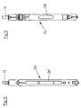
- Figure 12 shows in a very simplified representation and in side view as another possible embodiment a faceplate section 20 to which another Face plate section 21 connects.
- the transition 22 between these two Forend rail sections can be covered by a cover plate 23.
- the cover plate 7 is designed to be rectangular and lies at least in its state covering the transition 22 with its long sides 23 ' parallel to the longitudinal extent of the faceplate sections 20 and 21 and with their Narrow sides 23 "or 23 '' 'perpendicular to this longitudinal extension Transition 22 from the narrow side 23 ′′ lying further away is by means of the cover plate 23 an articulated connection 24 is articulated on the upper side of the faceplate section 20, in such a way that the cover plate 23 around the perpendicular to the longitudinal axis of the Cuff rail sections 20 and 21 and parallel to the top of the Cuff rail section 20 extending joint axis from the non-covering State in the state covering the transition 22 is pivotable, namely by screwing in a fastening screw 25, which has an opening in the cover plate 23 passes through, and against the action
- the spring action is, for example, by a spring in the area of the joint 24 or achieved in that the joint 24 or the cover plate 23rd is at least partially designed as a leaf spring-like element.
- an additional spring element 26 which acts like a leaf spring to provide, which is then between the cover plate 23 and the Faceplate section 20 acts and in the embodiment shown in the Space between the cover plate 23 and the top of the faceplate section 20th is arranged.
- the cover plate 23 Similar to the cover plate 7, the cover plate 23 also stands in its the transition 22 overlapping state only with a small part length over the free end of the faceplate section 20 in front.
- an imaginary plane is indicated by F, which is perpendicular to Longitudinal extension of the faceplate sections 20 and 21 and also perpendicular to the The top of these faceplate sections is and in which the transition 22nd forming end of the faceplate section 20 is arranged.
- the cover plate 23 has its narrow side 23 "on the side of this plane F facing the faceplate section 20, preferably at a distance from this plane, so that in the non-covering Condition of the cover plate 23 a simple assembly, among other things. of the faceplate section 21 is possible.
- cover plates 7 and 23 can be very general Transitions between faceplate sections are used and not only at Transitions in the area of corner drives.
Landscapes
- Engineering & Computer Science (AREA)
- Mechanical Engineering (AREA)
- Image-Pickup Tubes, Image-Amplification Tubes, And Storage Tubes (AREA)
- Operating, Guiding And Securing Of Roll- Type Closing Members (AREA)
Applications Claiming Priority (4)
| Application Number | Priority Date | Filing Date | Title |
|---|---|---|---|
| DE20105331 | 2001-03-26 | ||
| DE20105331U | 2001-03-26 | ||
| DE20105984U | 2001-04-05 | ||
| DE20105984U DE20105984U1 (de) | 2001-03-26 | 2001-04-05 | Stulpschiene für einen Treibstangenbeschlag für Fenster, Türen o.dgl. sowie Treibstangenbeschlag mit einer solchen Stulpschiene |
Publications (2)
| Publication Number | Publication Date |
|---|---|
| EP1245768A2 true EP1245768A2 (fr) | 2002-10-02 |
| EP1245768A3 EP1245768A3 (fr) | 2004-01-02 |
Family
ID=26056889
Family Applications (1)
| Application Number | Title | Priority Date | Filing Date |
|---|---|---|---|
| EP02003486A Withdrawn EP1245768A3 (fr) | 2001-03-26 | 2002-02-15 | Têtière d'une crémone pour fenêtres, portes ou similaires et crémone avec une telle têtière |
Country Status (1)
| Country | Link |
|---|---|
| EP (1) | EP1245768A3 (fr) |
Cited By (3)
| Publication number | Priority date | Publication date | Assignee | Title |
|---|---|---|---|---|
| EP2343425A1 (fr) * | 2009-12-15 | 2011-07-13 | Roto Frank Ag | Agencement de rails de partie de ferrure pour une fenêtre, une porte, un clapet ou analogue |
| EP2362043A1 (fr) * | 2010-02-19 | 2011-08-31 | Roto Frank Ag | Armature de bielle pour fenêtres, portes ou analogues, ainsi que fenêtre, porte ou analogue dotée d'une armature de bielle |
| WO2013046091A1 (fr) * | 2011-09-27 | 2013-04-04 | KOVINOPLASTIKA LOŽ Industrija kovinskih in plastičnih izdelkov d.d. | Raccord avec une ferrure de fenêtre et/ou de porte |
Citations (2)
| Publication number | Priority date | Publication date | Assignee | Title |
|---|---|---|---|---|
| DE2506003A1 (de) | 1975-02-13 | 1976-08-19 | Weidtmann Fa Wilhelm | Beschlag fuer fluegel von fenstern, tueren o.dgl. |
| DE19809698A1 (de) | 1998-03-06 | 1999-09-09 | Siegenia Frank Kg | Überlappungsverbindung |
Family Cites Families (4)
| Publication number | Priority date | Publication date | Assignee | Title |
|---|---|---|---|---|
| DE7819165U1 (de) * | 1978-06-26 | 1978-10-05 | Siegenia-Frank Kg, 5900 Siegen | Vorrichtung zur stosstellenueberlappung an stulpschienen |
| DE4019162C2 (de) * | 1990-06-15 | 2003-02-06 | Mayer & Co | Stulpschienenabdeckung |
| FR2772822B1 (fr) * | 1997-12-18 | 2000-02-04 | Ferco Int Usine Ferrures | Dispositif de liaison de tetiere |
| DE19814498B4 (de) * | 1998-04-01 | 2012-08-16 | Roto Frank Ag | Stulpschienenbeschlag |
-
2002
- 2002-02-15 EP EP02003486A patent/EP1245768A3/fr not_active Withdrawn
Patent Citations (2)
| Publication number | Priority date | Publication date | Assignee | Title |
|---|---|---|---|---|
| DE2506003A1 (de) | 1975-02-13 | 1976-08-19 | Weidtmann Fa Wilhelm | Beschlag fuer fluegel von fenstern, tueren o.dgl. |
| DE19809698A1 (de) | 1998-03-06 | 1999-09-09 | Siegenia Frank Kg | Überlappungsverbindung |
Cited By (3)
| Publication number | Priority date | Publication date | Assignee | Title |
|---|---|---|---|---|
| EP2343425A1 (fr) * | 2009-12-15 | 2011-07-13 | Roto Frank Ag | Agencement de rails de partie de ferrure pour une fenêtre, une porte, un clapet ou analogue |
| EP2362043A1 (fr) * | 2010-02-19 | 2011-08-31 | Roto Frank Ag | Armature de bielle pour fenêtres, portes ou analogues, ainsi que fenêtre, porte ou analogue dotée d'une armature de bielle |
| WO2013046091A1 (fr) * | 2011-09-27 | 2013-04-04 | KOVINOPLASTIKA LOŽ Industrija kovinskih in plastičnih izdelkov d.d. | Raccord avec une ferrure de fenêtre et/ou de porte |
Also Published As
| Publication number | Publication date |
|---|---|
| EP1245768A3 (fr) | 2004-01-02 |
Similar Documents
| Publication | Publication Date | Title |
|---|---|---|
| EP1441094A1 (fr) | Ferrure pour une fênetre | |
| DE2313690A1 (de) | Treibstangenbeschlag fuer fenster, tueren od.dgl | |
| EP0440987B2 (fr) | Crémone | |
| EP2252751B1 (fr) | Ferrure de tige d entraînement pour une fenêtre ou une porte | |
| EP0538562B1 (fr) | Cadre d'ouvrant muni d'une tringlere de manoeuvre, pour porte, fenêtre ou analogue | |
| DE19646982A1 (de) | Beschlag für ein Fenster | |
| DE3916216C2 (fr) | ||
| EP1264954B1 (fr) | Système de verouillage | |
| EP1256681B1 (fr) | Ferrure pour un élément de fermeture d'une ouverture dans un mur | |
| DE102015120559B3 (de) | Montageelement zur Befestigung von Türbändern | |
| DE19948862A1 (de) | Schließeinrichtung für einen Beschlag zur Verriegelung eines beweglichen Rahmenteils eines Fensters oder einer Tür | |
| EP2085551A2 (fr) | Dispositif de guidage pour un battant coulissant | |
| DE20105984U1 (de) | Stulpschiene für einen Treibstangenbeschlag für Fenster, Türen o.dgl. sowie Treibstangenbeschlag mit einer solchen Stulpschiene | |
| EP2343422A1 (fr) | Bloc d'armature pour une fenêtre, une porte, un clapet ou analogue | |
| EP3354833B1 (fr) | Renvoi d'angle de crémone | |
| DE19737538A1 (de) | Betätigungsgetriebe für einen Treibstangenbeschlag | |
| DE19502362C2 (de) | Positionierungseinrichtung für Beschlagteile | |
| DE19734647B4 (de) | Beschlagteil an einem Flügel oder einem festen Rahmen eines Fensters, einer Tür od. dgl. | |
| EP1067264B1 (fr) | Système de tringle de commande et têtière à élément d'insert pour une telle système | |
| EP3783176B1 (fr) | Ferrure de tige d'entraînement, fermeture de porte ou de fenêtre et agencement de porte ou de fenêtre | |
| DE4339752C2 (de) | Beschlaganordnung für Flügel von Fenstern oder Türen | |
| DE69500536T2 (de) | Verriegelungsvorrichtung für den halbbefestigten Flügel eines Fensters mit zwei Flügeln | |
| DE10154477A1 (de) | Kupplungsvorrichtung | |
| EP0843061B1 (fr) | Ferrure pour fenêtre | |
| EP1977065B1 (fr) | Renvoi d'angle |
Legal Events
| Date | Code | Title | Description |
|---|---|---|---|
| PUAI | Public reference made under article 153(3) epc to a published international application that has entered the european phase |
Free format text: ORIGINAL CODE: 0009012 |
|
| AK | Designated contracting states |
Kind code of ref document: A2 Designated state(s): AT BE CH CY DE DK ES FI FR GB GR IE IT LI LU MC NL PT SE TR |
|
| AX | Request for extension of the european patent |
Free format text: AL;LT;LV;MK;RO;SI |
|
| PUAL | Search report despatched |
Free format text: ORIGINAL CODE: 0009013 |
|
| AK | Designated contracting states |
Kind code of ref document: A3 Designated state(s): AT BE CH CY DE DK ES FI FR GB GR IE IT LI LU MC NL PT SE TR |
|
| AX | Request for extension of the european patent |
Extension state: AL LT LV MK RO SI |
|
| RIC1 | Information provided on ipc code assigned before grant |
Ipc: 7E 05C 9/00 B Ipc: 7E 05C 9/06 B Ipc: 7E 05C 9/24 B Ipc: 7E 05C 9/22 A |
|
| 17P | Request for examination filed |
Effective date: 20040209 |
|
| AKX | Designation fees paid |
Designated state(s): AT DE FR IT |
|
| 17Q | First examination report despatched |
Effective date: 20070208 |
|
| STAA | Information on the status of an ep patent application or granted ep patent |
Free format text: STATUS: THE APPLICATION IS DEEMED TO BE WITHDRAWN |
|
| 18D | Application deemed to be withdrawn |
Effective date: 20070821 |