EP1245809A2 - Method for controlling idling speed of internal combustion engine - Google Patents
Method for controlling idling speed of internal combustion engine Download PDFInfo
- Publication number
- EP1245809A2 EP1245809A2 EP02007155A EP02007155A EP1245809A2 EP 1245809 A2 EP1245809 A2 EP 1245809A2 EP 02007155 A EP02007155 A EP 02007155A EP 02007155 A EP02007155 A EP 02007155A EP 1245809 A2 EP1245809 A2 EP 1245809A2
- Authority
- EP
- European Patent Office
- Prior art keywords
- engine speed
- injection amount
- speed
- engine
- idling
- Prior art date
- Legal status (The legal status is an assumption and is not a legal conclusion. Google has not performed a legal analysis and makes no representation as to the accuracy of the status listed.)
- Granted
Links
Images



Classifications
-
- F—MECHANICAL ENGINEERING; LIGHTING; HEATING; WEAPONS; BLASTING
- F02—COMBUSTION ENGINES; HOT-GAS OR COMBUSTION-PRODUCT ENGINE PLANTS
- F02D—CONTROLLING COMBUSTION ENGINES
- F02D31/00—Use of speed-sensing governors to control combustion engines, not otherwise provided for
- F02D31/001—Electric control of rotation speed
- F02D31/007—Electric control of rotation speed controlling fuel supply
- F02D31/008—Electric control of rotation speed controlling fuel supply for idle speed control
-
- F—MECHANICAL ENGINEERING; LIGHTING; HEATING; WEAPONS; BLASTING
- F02—COMBUSTION ENGINES; HOT-GAS OR COMBUSTION-PRODUCT ENGINE PLANTS
- F02D—CONTROLLING COMBUSTION ENGINES
- F02D41/00—Electrical control of supply of combustible mixture or its constituents
- F02D41/02—Circuit arrangements for generating control signals
- F02D41/04—Introducing corrections for particular operating conditions
- F02D41/12—Introducing corrections for particular operating conditions for deceleration
-
- F—MECHANICAL ENGINEERING; LIGHTING; HEATING; WEAPONS; BLASTING
- F02—COMBUSTION ENGINES; HOT-GAS OR COMBUSTION-PRODUCT ENGINE PLANTS
- F02D—CONTROLLING COMBUSTION ENGINES
- F02D41/00—Electrical control of supply of combustible mixture or its constituents
- F02D41/02—Circuit arrangements for generating control signals
- F02D41/14—Introducing closed-loop corrections
- F02D41/16—Introducing closed-loop corrections for idling
-
- F—MECHANICAL ENGINEERING; LIGHTING; HEATING; WEAPONS; BLASTING
- F02—COMBUSTION ENGINES; HOT-GAS OR COMBUSTION-PRODUCT ENGINE PLANTS
- F02D—CONTROLLING COMBUSTION ENGINES
- F02D2200/00—Input parameters for engine control
- F02D2200/02—Input parameters for engine control the parameters being related to the engine
- F02D2200/10—Parameters related to the engine output, e.g. engine torque or engine speed
- F02D2200/1012—Engine speed gradient
-
- F—MECHANICAL ENGINEERING; LIGHTING; HEATING; WEAPONS; BLASTING
- F02—COMBUSTION ENGINES; HOT-GAS OR COMBUSTION-PRODUCT ENGINE PLANTS
- F02D—CONTROLLING COMBUSTION ENGINES
- F02D41/00—Electrical control of supply of combustible mixture or its constituents
- F02D41/02—Circuit arrangements for generating control signals
- F02D41/04—Introducing corrections for particular operating conditions
- F02D41/12—Introducing corrections for particular operating conditions for deceleration
- F02D41/123—Introducing corrections for particular operating conditions for deceleration the fuel injection being cut-off
- F02D41/126—Introducing corrections for particular operating conditions for deceleration the fuel injection being cut-off transitional corrections at the end of the cut-off period
Definitions
- the present invention relates to a method for controlling an idling speed of an internal combustion engine in which an injection amount is controlled by a feedback method so as to keep a target engine speed when a vehicle runs under an idling condition after a driver takes his or her foot off an accelerator while the vehicle runs.
- An idling speed of an engine becomes stable at a rotating speed where a generated torque of the engine and a load torque caused by a friction in the engine itself balance. For example, if temperature is low, the idling speed is lowered since the friction in the engine itself is increased resulted from an increased viscosity of the engine lubricant oil. However, if the idling speed is lowered, the engine speed gets unstable, therefore there is a possibility that the driver get an uncomfortable feeling. On the other hand, if the idling speed is too high, the engine noise may be increased and the fuel economy may be lowered.
- idling speed control a method for controlling the injection amount to a value that is necessary to keep the target idling speed even if the load torque of the engine is changed. That is called as an idling speed control.
- an actual engine speed and a target engine speed obtained based on conditions such as a engine cooling water temperature and a load of a compressor for an air conditioner, and the injection amount is controlled by a PI type feedback method so that the target engine speed is achieved in accordance with a difference between those of the engine speeds.
- the actual engine speed may repeat overshoots until the actual engine speed Ne convergences to the target engine speed Neisc.
- the repeated overshoots are triggered by insignificant hunting oscillations caused by the PI type feedback control, and causes a disadvantage that the driver may have unevenness about a drive feeling.
- the present invention was accomplished in consideration of the above-mentioned circumstances, it is an abject of the present invention to provide a method for controlling an idling speed of an internal combustion engine, which is capable of approaching the actual engine speed to the target engine speed smoothly during the idling speed control executed when the vehicle runs under the idling condition after the driver takes foot off the accelerator while running the vehicle.
- the method for controlling the idling speed of the present invention is characterized by executing a injection correcting control for correcting the injection amount in order to suppress an excessive drop of the engine speed (decreasing speed) caused by a feedback control of the injection amount in accordance with a difference between an actual engine speed and a target engine speed.
- the injection correcting control may comprises a step of calculating a corrective injection amount based on a decreasing speed of the engine speed. It is possible to suppress a decreasing speed of the engine speed relative to a decreasing speed caused by injecting a usual injection amount.
- the injection correcting control may comprises a step of gradually increasing the corrective injection amount as the actual engine speed approaches to the target engine speed when the actual engine speed closely approaches to the target engine speed so that 100 % of the corrective injection amount affects the engine speed. It is possible to prevent the engine speed from an excessive quick deviation, and the driver is prevented from an uncomfortable shock feeling.
- the corrective injection amount may be different with respect to an engine load. It is possible to execute the injection correcting control appropriately by varying the corrective injection amount in accordance with the engine load, e.g. the corrective injection amount is increased as the gear ratio is increased.
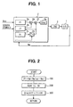
- FIG. 1 is a control block diagram of the embodiment
- FIGS. 2 through 4 are flowcharts showing processing order of an ECU which executes an idling speed control.
- the idling speed control is applied to a diesel engine 1.
- the idling speed control executes a feedback control of an injection amount by driving an injection device 3 via an Electronic Control Unit 2 so as to coincide an actual engine speed Ne with a target engine speed Neisc when a vehicle runs under an idling condition after a driver takes foot off an accelerator pedal while running a vehicle. That is, during the driver taking foot off the accelerator, an operating degree of the accelerator is 0.
- the ECU 2 inputs the operating degree of the accelerator and other sensor signals such as the engine speed Ne.
- the ECU 2 has a block 2a for obtaining a proportional component of an injection amount in accordance with a difference (Neisc - Ne) between the engine speed Ne and the target engine speed Neisc.
- the ECU 2 has a block 2b for obtaining an integral component of the injection amount in accordance with the difference.
- the ECU 2 also has a block 2c for obtaining a differential component of the injection amount in accordance with the decreasing speed of the engine speed.
- the ECU 2 has a switch block 2d for controlling the differential component in accordance with conditions of the vehicle and the engine.
- the ECU 2 has adding blocks 2e and 2f for adding the components to obtain a conclusive corrective injection amount Qisc.
- the ECU 2 has a block 2g for calculating a base injection amount Qbase for maintaining the engine rotation in accordance with the operating degree of the accelerator and the engine speed, for calculating a conclusive injection amount Q by summing the base injection amount Qbase and the conclusive corrective injection amount Qisc, and for controlling the injection device 3 so as to inject and supply the conclusive injection amount Q to the engine 1.
- a processing order of the idling speed control with the ECU 2 is explained with reference to a base routine shown in FIG. 2 and subroutines shown in FIGS. 3 and 4. Hereinafter, functions of each step are explained step by step.
- a corrective amount Pi for P term, proportional component is calculated by the following expression (1).
- the corrective amount Pi is calculated as a base injection amount for an idling speed control.
- Pi Kp ⁇ (Neisc - Ne)
- a step 200 corrective amounts Ii and Di for I and D terms, integral and differential components, are calculated and read into the main routine.
- a conclusive corrective injection amount Qisc is calculated by summing the corrective amounts Pi, Ii and Di.
- a step 201 it is determined that whether an initial process is completed or not. In the initial process, for instance, it is determined that whether an engine-starting switch (an ignition key) is turned on or not. If the engine-starting switch is turned on (YES) the process proceeds to a step 202, if the engine-starting switch is already turned on (NO) the process proceeds to a step 203.
- an engine-starting switch an ignition key
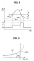
- steps 203 through 210 conditions of the vehicle are determined into three categories as shown in FIG. 5.
- a step 204 it is determined that whether the following EVENT A is satisfied or not.
- EVENT A Ne ⁇ Neisc + ⁇ N2, or the driver takes foot off the accelerator and Ne is not changed (is stable).
- ⁇ N2 is a threshold value to determine whether the correction of D term should be stopped or not a shown in FIG. 5. If the EVENT A is satisfied (YES) the process proceeds to the step 205, if it is not satisfied (NO) the process proceeds to the step 208.
- a step 207 it is determined that whether the following EVENT B is satisfied or not.
- EVENT B Ne ⁇ Neisc + ⁇ N1.
- ⁇ N1 is a threshold value to determine whether the Di term correction should be executed or not as shown in FIG. 5. If the EVENT B is satisfied (YES) the process proceeds to the step 208, if it is not satisfied (NO) the process proceeds to the step 210.
- a step 209 it is determined that whether the following EVENT C is satisfied or not.
- EVENT C Ne ⁇ Neisc + ⁇ N1. If the EVENT C is satisfied (YES) the process proceeds to the step 210, if the EVENT C is not satisfied (NO) the process proceeds to the step 205.
- the ⁇ N1 is a greater value than the ⁇ N2.
- a differential component is calculated. The step 212 is activated only when the engine speed is approaching to the target engine speed and the engine speed is within a predetermined range.
- the process proceeds to a step 213 after calculating the corrective amount Di for the D term by the following expression (2).
- Di Kd ⁇ dNe/dt Kd: coefficient (affecting ratio coefficient), dNe/dt: decreasing speed of the Ne.
- the coefficient Kd is obtained as the product of a coefficient Kd1 and Kd2 as shown in FIGS. 6 and 7.
- the coefficient Kd1 is obtained based on a difference between the Ne and the Neisc.
- the coefficient Kd1 is set to increase the corrective amount gradually so as to affect 100 % of the corrective amount for Di term when the engine speed Ne coincides with the target engine speed Neisc.
- the coefficient Fd2 is determined by parameters such as an engine load as shown in FIG.
- the load may be obtained by a signal from a transmission indicative of gear positions. For example, it is necessary to increase torque generated by the engine 1 to obtain an even torque (deceleration) on a driving wheel as a gear position (ratio) is increased. Therefore, the corrective injection amount is also increased.
- a step 213 the process proceeds to a step 220 after replacing the corrective amount Ii-1 calculated in the last time with the present corrective amount Ii.
- a step 216 the process proceeds to a step 217 after calculating the corrective amount Ii for the I term by the following expression (3).
- Ii Ii-1 + Di
- a step 218 the process proceeds to the step 220 after calculating the corrective amount Ii by the following expression (4).
- Ii Ii-1
- a step 210 the process proceeds to the step 220 after calculating the corrective amount Ii by the following expression (5).
- Ii Ii-1 + f(Neisc - Ne)
- a step 220 the corrective amounts Ii-1 and Di-1 calculated in the last time are replaced with the corrective amounts Ii and Di calculated in the present process.
- a corrective injection amount for correcting the injection amount is obtained on a vicinity of the target engine speed (Neisc + ⁇ N2 ⁇ Ne ⁇ Neisc + ⁇ N1). Therefore, it is possible to suppress a decreasing speed of the engine speed relative to a conventional idling speed control using a PI type feedback control. Accordingly, it is possible to prevent the engine speed from an excessive drop (overshoot) with respect to the target engine speed. It is possible to approach the engine speed smoothly to the target engine speed as shown in FIG. 8 with a solid line.
- a corrective injection amount is calculated and added on a base injection amount when the engine speed is in a vicinity of the target engine speed (Neisc + ⁇ N2 ⁇ Ne ⁇ Neisc + ⁇ N1).
- the corrective injection amount is calculated based on a decreasing speed dNe/dt of the Ne.
- the corrective amount is gradually increased by an affecting ratio coefficient Kd1 so that 100 % of the corrective amount is fully effective when the engine speed Ne coincides with the target engine speed Neisc.
- Kd1 ratio coefficient
Landscapes
- Engineering & Computer Science (AREA)
- Chemical & Material Sciences (AREA)
- Combustion & Propulsion (AREA)
- Mechanical Engineering (AREA)
- General Engineering & Computer Science (AREA)
- Electrical Control Of Air Or Fuel Supplied To Internal-Combustion Engine (AREA)
- Control Of Vehicle Engines Or Engines For Specific Uses (AREA)
Abstract
Description
Claims (10)
- A method for controlling an idling speed of an internal combustion engine (1), the method comprising the steps of:controlling an injection amount by a feedback method so as to maintain a target engine speed when a vehicle runs under an idling condition after a driver takes foot off an accelerator while running a vehicle, characterized in thatthe injection amount is corrected (2b, 2c, 2e, 2f) in order to suppress an excessive drop of the engine speed that may be caused by a feedback control of the injection amount in accordance with a difference between an actual engine speed and a target engine speed.
- The method for controlling the idling speed of the internal combustion engine according to claim 1, wherein the method comprising the steps of:calculating (2a) a base injection amount (Pi) for an idling speed control in accordance with a difference (Neisc - Ne) between the actual engine speed and the target engine speed;calculating (2b, 2c) a corrective injection amount (Di) based on a decreasing speed (dNe/dt) of the engine speed;obtaining (2e, 2f) a conclusive injection amount (Qisc) for the idling speed control by summing the base injection amount and the corrective injection amount.
- The method for controlling the idling speed of the internal combustion engine according to claim 2, further comprising the step of gradually increasing (2c) the corrective injection amount (Di) as the actual engine speed approaches to the target engine speed so that 100 % of the corrective injection amount affects the engine speed when the actual engine speed is substantially coincide with the target engine speed.
- The method for controlling the idling speed of the internal combustion engine according to claim 2 or 3, wherein the corrective injection amount is different with respect to an engine load.
- The method for controlling the idling speed of the internal combustion engine according to one of claims 2 through 4, wherein the step of calculating (2c) the corrective injection amount (Di) based on the decreasing speed (dNe/dt) of the engine speed is activated only when the engine speed is approaching to the target engine speed and the engine speed is within a predetermined range (Neisc + ΔN2 ≤ Ne < Neisc + Δn1).
- The method for controlling the idling speed of the internal combustion engine according to one of claims 2 through 5, wherein the method further comprising the steps of:calculating a base injection amount (Qbase) for rotating the engine;calculating a conclusive injection amount (Q) by summing the base injection amount (Qbase) and the conclusive injection amount (Qisc) for the idling speed control; andinjecting the conclusive injection amount (Q) into the engine.
- The method for controlling the idling speed of the internal combustion engine according to claim 1, wherein the method comprising the steps of:calculating a base injection amount (Qbase) for rotating the engine;calculating a proportional component (Pi) for executing an idling speed control based on a difference (Neisc - Ne) between the engine speed and the target engine speed;calculating a conclusive injection amount (Q) by summing the base injection amount (Qbase) and the proportional component (Pi);injecting the conclusive injection amount (Q) to the engine;calculating a differential component (Di) for executing an idling speed control based on a decreasing speed (dNe/dt) of the engine speed;calculating a conclusive injection amount (Q) by summing the base injection amount (Qbase), the proportional component (Pi) and the differential component (Di) when the engine speed is within a predetermined range (Neisc + ΔN2 ≤ Ne < Neisc + Δn1) which is set slightly above the target engine speed; andinjecting the conclusive injection amount (Q) to the engine when the engine speed is within the predetermined range.
- The method for controlling the idling speed of the internal combustion engine according to claim 7, wherein the differential component (Di) is calculated so as to increase the differential component as the engine speed approaches to the target engine speed.
- The method for controlling the idling speed of the internal combustion engine according to claim 7, wherein the differential component (Di) is calculated so as to affect 100 % of the differential component affects the idling speed control when the engine speed substantially coincide with the target engine speed.
- The method for controlling the idling speed of the internal combustion engine according to claim 7, wherein the differential component (Di) is calculated so as to increase the differential component as an engine load increases.
Applications Claiming Priority (2)
| Application Number | Priority Date | Filing Date | Title |
|---|---|---|---|
| JP2001095573 | 2001-03-29 | ||
| JP2001095573A JP2002295291A (en) | 2001-03-29 | 2001-03-29 | Idle speed control method for internal combustion engine |
Publications (3)
| Publication Number | Publication Date |
|---|---|
| EP1245809A2 true EP1245809A2 (en) | 2002-10-02 |
| EP1245809A3 EP1245809A3 (en) | 2004-11-10 |
| EP1245809B1 EP1245809B1 (en) | 2009-01-14 |
Family
ID=18949598
Family Applications (1)
| Application Number | Title | Priority Date | Filing Date |
|---|---|---|---|
| EP20020007155 Expired - Lifetime EP1245809B1 (en) | 2001-03-29 | 2002-03-28 | Method for controlling idling speed of internal combustion engine |
Country Status (3)
| Country | Link |
|---|---|
| EP (1) | EP1245809B1 (en) |
| JP (1) | JP2002295291A (en) |
| DE (1) | DE60230831D1 (en) |
Cited By (8)
| Publication number | Priority date | Publication date | Assignee | Title |
|---|---|---|---|---|
| US6755176B2 (en) | 2002-03-01 | 2004-06-29 | Denso Corporation | Fuel injection control system for engine |
| DE102004001723A1 (en) * | 2004-01-13 | 2005-08-18 | Volkswagen Ag | Control system for IC engine with continuous lambda control has programmed additional fuel added to injection pulses as actual engine speed exceeds threshold value to prevent undue swing about nominal idling value |
| WO2006029945A1 (en) * | 2004-09-15 | 2006-03-23 | Siemens Aktiengesellschaft | Method for controlling an internal combustion engine in the neutral position |
| US7021288B2 (en) * | 2003-10-31 | 2006-04-04 | Denso Corporation | Injection control apparatus for an engine |
| FR2923862A1 (en) * | 2007-11-19 | 2009-05-22 | Renault Sas | Internal combustion engine e.g. gasoline engine, controlling method for vehicle, involves controlling engine speed at idling phase inlet, with dynamic speed setpoint rule between initial engine speed and final speed setpoint |
| US8336315B2 (en) | 2004-02-18 | 2012-12-25 | Siemens Aktiengesellschaft | Gas turbine with a compressor housing which is protected against cooling down and method for operating a gas turbine |
| CN103047034A (en) * | 2012-12-28 | 2013-04-17 | 潍柴动力股份有限公司 | Low-idle-speed control method and low-idle-speed control device |
| CN115142973A (en) * | 2022-07-01 | 2022-10-04 | 奇瑞汽车股份有限公司 | Engine idling anti-flameout control method and device |
Families Citing this family (5)
| Publication number | Priority date | Publication date | Assignee | Title |
|---|---|---|---|---|
| JP3966096B2 (en) | 2002-06-20 | 2007-08-29 | 株式会社デンソー | Injection amount control device for internal combustion engine |
| JP4277677B2 (en) * | 2003-06-27 | 2009-06-10 | 株式会社デンソー | Injection quantity control device for diesel engine |
| JP4710888B2 (en) | 2007-08-23 | 2011-06-29 | 株式会社デンソー | Diesel engine fuel injection control device and diesel engine fuel injection amount learning method |
| JP2009057853A (en) | 2007-08-30 | 2009-03-19 | Denso Corp | Internal combustion engine fuel injection control device and internal combustion engine fuel injection amount learning method |
| CA2754137C (en) | 2011-09-30 | 2012-11-20 | Westport Power Inc. | Apparatus and method for in situ fuel injector calibration in an internal combustion engine |
Family Cites Families (4)
| Publication number | Priority date | Publication date | Assignee | Title |
|---|---|---|---|---|
| DE3226283A1 (en) * | 1982-07-14 | 1984-01-19 | Vdo Adolf Schindling Ag, 6000 Frankfurt | IDLE CONTROLLER, IN PARTICULAR FOR MOTOR VEHICLES |
| US4520778A (en) * | 1983-10-11 | 1985-06-04 | Kokusan Denki Co., Ltd. | Method of controlling engine speed for internal combustion engine |
| DE4112848C2 (en) * | 1991-04-19 | 2001-11-15 | Bosch Gmbh Robert | System for controlling the idle speed of an internal combustion engine |
| FR2707347B1 (en) * | 1993-07-06 | 1995-09-22 | Siemens Automotive Sa | Method and device for controlling the speed of an internal combustion engine in the idle phase. |
-
2001
- 2001-03-29 JP JP2001095573A patent/JP2002295291A/en active Pending
-
2002
- 2002-03-28 DE DE60230831T patent/DE60230831D1/en not_active Expired - Lifetime
- 2002-03-28 EP EP20020007155 patent/EP1245809B1/en not_active Expired - Lifetime
Cited By (11)
| Publication number | Priority date | Publication date | Assignee | Title |
|---|---|---|---|---|
| US6755176B2 (en) | 2002-03-01 | 2004-06-29 | Denso Corporation | Fuel injection control system for engine |
| US7021288B2 (en) * | 2003-10-31 | 2006-04-04 | Denso Corporation | Injection control apparatus for an engine |
| DE102004001723A1 (en) * | 2004-01-13 | 2005-08-18 | Volkswagen Ag | Control system for IC engine with continuous lambda control has programmed additional fuel added to injection pulses as actual engine speed exceeds threshold value to prevent undue swing about nominal idling value |
| US8336315B2 (en) | 2004-02-18 | 2012-12-25 | Siemens Aktiengesellschaft | Gas turbine with a compressor housing which is protected against cooling down and method for operating a gas turbine |
| WO2006029945A1 (en) * | 2004-09-15 | 2006-03-23 | Siemens Aktiengesellschaft | Method for controlling an internal combustion engine in the neutral position |
| US7530344B2 (en) | 2004-09-15 | 2009-05-12 | Siemens Aktiengesellschaft | Method for controlling an internal combustion engine in the neutral position |
| FR2923862A1 (en) * | 2007-11-19 | 2009-05-22 | Renault Sas | Internal combustion engine e.g. gasoline engine, controlling method for vehicle, involves controlling engine speed at idling phase inlet, with dynamic speed setpoint rule between initial engine speed and final speed setpoint |
| CN103047034A (en) * | 2012-12-28 | 2013-04-17 | 潍柴动力股份有限公司 | Low-idle-speed control method and low-idle-speed control device |
| CN103047034B (en) * | 2012-12-28 | 2016-02-10 | 潍柴动力股份有限公司 | A kind of low idle speed control and device |
| CN115142973A (en) * | 2022-07-01 | 2022-10-04 | 奇瑞汽车股份有限公司 | Engine idling anti-flameout control method and device |
| CN115142973B (en) * | 2022-07-01 | 2023-07-28 | 奇瑞汽车股份有限公司 | Engine idling flameout prevention control method and device |
Also Published As
| Publication number | Publication date |
|---|---|
| EP1245809A3 (en) | 2004-11-10 |
| DE60230831D1 (en) | 2009-03-05 |
| JP2002295291A (en) | 2002-10-09 |
| EP1245809B1 (en) | 2009-01-14 |
Similar Documents
| Publication | Publication Date | Title |
|---|---|---|
| EP1245809B1 (en) | Method for controlling idling speed of internal combustion engine | |
| EP2297441B1 (en) | Fuel injection amount control apparatus for internal combustion engine, control system for power unit, and fuel injection amount control method for internal combustion engine | |
| US7797992B2 (en) | Control apparatus for a source of rotational drive force | |
| US6106432A (en) | Output power control apparatus for internal combustion engine of motor vehicle | |
| US6019085A (en) | Throttle valve control device for internal-combustion engine | |
| US5299539A (en) | Method for controlling rotational speed of an internal combustion engine | |
| US7069904B2 (en) | Method for regulating the speed of an internal combustion engine | |
| US6925985B2 (en) | Method and device for controlling the speed of an internal combustion engine | |
| US6855092B2 (en) | Throttle control method and method of selecting powertrain objectives | |
| US20060118083A1 (en) | Method for regulating the rotational speed of an internal combustion engine | |
| US5806486A (en) | Automative engine idle speed control | |
| US20040079329A1 (en) | Method of controlling the rotational speed of a drive unit | |
| JP2002061536A (en) | Method and apparatus for operating an internal combustion engine | |
| EP1455073B1 (en) | Output control apparatus of internal combustion engine | |
| JPH0534497B2 (en) | ||
| US6095120A (en) | Fuel injection system and method for an air-compressing internal-combustion engine | |
| JP3323819B2 (en) | Air conditioner control method | |
| KR100354016B1 (en) | Method for engine controlling of vehicle | |
| JP2008274764A (en) | Method and device for controlling output of internal combustion engine | |
| US11639694B2 (en) | Vehicle control system | |
| JPH05312076A (en) | Idle speed control device | |
| JP3035427B2 (en) | Idle speed control method | |
| KR100305791B1 (en) | Fuel injection method when idle driving of vehicle | |
| JP2660616B2 (en) | Idle speed control device for internal combustion engine | |
| US6832975B2 (en) | Method for controlling an internal combustion engine |
Legal Events
| Date | Code | Title | Description |
|---|---|---|---|
| PUAI | Public reference made under article 153(3) epc to a published international application that has entered the european phase |
Free format text: ORIGINAL CODE: 0009012 |
|
| AK | Designated contracting states |
Kind code of ref document: A2 Designated state(s): AT BE CH CY DE DK ES FI FR GB GR IE IT LI LU MC NL PT SE TR |
|
| AX | Request for extension of the european patent |
Free format text: AL;LT;LV;MK;RO;SI |
|
| PUAL | Search report despatched |
Free format text: ORIGINAL CODE: 0009013 |
|
| AK | Designated contracting states |
Kind code of ref document: A3 Designated state(s): AT BE CH CY DE DK ES FI FR GB GR IE IT LI LU MC NL PT SE TR |
|
| AX | Request for extension of the european patent |
Extension state: AL LT LV MK RO SI |
|
| 17P | Request for examination filed |
Effective date: 20050318 |
|
| AKX | Designation fees paid |
Designated state(s): DE FR SE |
|
| 17Q | First examination report despatched |
Effective date: 20061228 |
|
| GRAP | Despatch of communication of intention to grant a patent |
Free format text: ORIGINAL CODE: EPIDOSNIGR1 |
|
| GRAS | Grant fee paid |
Free format text: ORIGINAL CODE: EPIDOSNIGR3 |
|
| GRAA | (expected) grant |
Free format text: ORIGINAL CODE: 0009210 |
|
| AK | Designated contracting states |
Kind code of ref document: B1 Designated state(s): DE FR SE |
|
| REF | Corresponds to: |
Ref document number: 60230831 Country of ref document: DE Date of ref document: 20090305 Kind code of ref document: P |
|
| REG | Reference to a national code |
Ref country code: SE Ref legal event code: TRGR |
|
| PLBE | No opposition filed within time limit |
Free format text: ORIGINAL CODE: 0009261 |
|
| STAA | Information on the status of an ep patent application or granted ep patent |
Free format text: STATUS: NO OPPOSITION FILED WITHIN TIME LIMIT |
|
| 26N | No opposition filed |
Effective date: 20091015 |
|
| PGFP | Annual fee paid to national office [announced via postgrant information from national office to epo] |
Ref country code: FR Payment date: 20120319 Year of fee payment: 11 |
|
| PGFP | Annual fee paid to national office [announced via postgrant information from national office to epo] |
Ref country code: SE Payment date: 20120313 Year of fee payment: 11 |
|
| PGFP | Annual fee paid to national office [announced via postgrant information from national office to epo] |
Ref country code: DE Payment date: 20120411 Year of fee payment: 11 |
|
| REG | Reference to a national code |
Ref country code: SE Ref legal event code: EUG |
|
| PG25 | Lapsed in a contracting state [announced via postgrant information from national office to epo] |
Ref country code: SE Free format text: LAPSE BECAUSE OF NON-PAYMENT OF DUE FEES Effective date: 20130329 |
|
| REG | Reference to a national code |
Ref country code: FR Ref legal event code: ST Effective date: 20131129 |
|
| REG | Reference to a national code |
Ref country code: DE Ref legal event code: R119 Ref document number: 60230831 Country of ref document: DE Effective date: 20131001 |
|
| PG25 | Lapsed in a contracting state [announced via postgrant information from national office to epo] |
Ref country code: FR Free format text: LAPSE BECAUSE OF NON-PAYMENT OF DUE FEES Effective date: 20130402 Ref country code: DE Free format text: LAPSE BECAUSE OF NON-PAYMENT OF DUE FEES Effective date: 20131001 |