EP1245883B1 - Rohrschelle - Google Patents
Rohrschelle Download PDFInfo
- Publication number
- EP1245883B1 EP1245883B1 EP02362006A EP02362006A EP1245883B1 EP 1245883 B1 EP1245883 B1 EP 1245883B1 EP 02362006 A EP02362006 A EP 02362006A EP 02362006 A EP02362006 A EP 02362006A EP 1245883 B1 EP1245883 B1 EP 1245883B1
- Authority
- EP
- European Patent Office
- Prior art keywords
- segments
- collar
- base
- segment
- pipe
- Prior art date
- Legal status (The legal status is an assumption and is not a legal conclusion. Google has not performed a legal analysis and makes no representation as to the accuracy of the status listed.)
- Expired - Lifetime
Links
- 230000008878 coupling Effects 0.000 claims abstract description 3
- 238000010168 coupling process Methods 0.000 claims abstract description 3
- 238000005859 coupling reaction Methods 0.000 claims abstract description 3
- 239000000463 material Substances 0.000 claims description 8
- 238000000465 moulding Methods 0.000 claims description 5
- 230000000712 assembly Effects 0.000 description 3
- 238000000429 assembly Methods 0.000 description 3
- 230000000694 effects Effects 0.000 description 3
- 230000003042 antagnostic effect Effects 0.000 description 1
Images


Classifications
-
- F—MECHANICAL ENGINEERING; LIGHTING; HEATING; WEAPONS; BLASTING
- F16—ENGINEERING ELEMENTS AND UNITS; GENERAL MEASURES FOR PRODUCING AND MAINTAINING EFFECTIVE FUNCTIONING OF MACHINES OR INSTALLATIONS; THERMAL INSULATION IN GENERAL
- F16L—PIPES; JOINTS OR FITTINGS FOR PIPES; SUPPORTS FOR PIPES, CABLES OR PROTECTIVE TUBING; MEANS FOR THERMAL INSULATION IN GENERAL
- F16L3/00—Supports for pipes, cables or protective tubing, e.g. hangers, holders, clamps, cleats, clips, brackets
- F16L3/08—Supports for pipes, cables or protective tubing, e.g. hangers, holders, clamps, cleats, clips, brackets substantially surrounding the pipe, cable or protective tubing
- F16L3/12—Supports for pipes, cables or protective tubing, e.g. hangers, holders, clamps, cleats, clips, brackets substantially surrounding the pipe, cable or protective tubing comprising a member substantially surrounding the pipe, cable or protective tubing
- F16L3/1203—Supports for pipes, cables or protective tubing, e.g. hangers, holders, clamps, cleats, clips, brackets substantially surrounding the pipe, cable or protective tubing comprising a member substantially surrounding the pipe, cable or protective tubing with a pair of arms moved automatically to closed position by overcenter spring
Definitions
- the present invention relates to an adaptable pipe fastening collar and more specifically to a collar adapted to ensure the attachment to the choice, at the laying site, of pipes having an external diameter according to one or the other of two predetermined values. .
- the invention aims at an improvement to the type of collar known from FR 2 344 776.
- This document describes a hose clamp comprising two flange segments hinged to a fastening element of the collar via a hinge connecting said element to a central outer part of each segment.
- the flange segments At their opposite end to the fastening element, the flange segments comprise mutual engagement means when said segments are in a position where they surround the pipe to be fixed.
- the whole collar is monobloc and made by molding a suitable plastic material having a certain elasticity.
- the flange segments of the collar are spaced apart and leave between them a passage for fixing the collar on a support, then the engagement of the pipe to be fixed, the latter being presented with its axis parallel to the axis of the flange defined by the segments.
- the pipe is thus introduced into the space between the segments and pressed in the direction of the fastening element of the collar so that, by an elastic rocking effect on said segments, the latter is closed around the pipe until the interlocking ends provided with said attachment means.
- Such a device allows the attachment of pipes having an outer diameter equal to or very substantially equal to the internal diameter of the flange defined by the segments in the locked position.
- the present invention aims to overcome these problems by proposing an improvement to the type of collar according to FR 2 344 776, allowing the rapid fixing of pipes of two different diameters determined by implementing simple means, easy to achieve and inexpensive, while ensuring secure and firm fixation.
- FR 2 594 903 A1 discloses a collar comprising a pair of external jaws and a pair of internal jaws for which the inner jaws, in spaced position, bear against the inner face of the outer jaws.
- an adaptable pipe fixing collar comprising a fixing base, two first antagonistic flange segments articulated on said base by means of a hinge connecting the base to a central external part. of each segment, the ends of said segments opposite said base being provided with mutual coupling means, wherein said first segments are each provided with a second flange segment, of greater curvature than that of the first segments, said second segments being disposed opposite one another and connected at their ends to the first segments by hinges and being able to occupy, at choice, one or other of two stable end positions, one, in which they protrude into the space between the first segments, so, at the closing of the first segments, to constitute a second flange of smaller diameter than that of the flange formed by the first segments and the other said retracted position, wherein the second segments are likely to be pushed into an opening in the first segments.
- the small diameter pipe is put in place in the collar in exactly the same manner as in the collar of known type not equipped with the improvements according to the invention, the second flange segments being in projecting position in the space between the first segments. .
- both the first flange segments and the second segments are closed like a jaw, the pipe being clamped in said second flange segments.
- the second flange segments are retracted out of the gap between the first segments and the pipe is set up in the same way.
- the first flange segments are closed on the pipe.
- the second flange segments have a substantially common end with the end, base side, of the first segments, while the other end is connected by a deformable elastic bridging to the first segment, near the end of the first segment opposite to the base, each set second segment - bridging being capable, in said retracted position, to completely clear said space between the first segments.
- Such a collar is particularly simple and yet practical and effective, while being achievable particularly economically by simply molding a piece of a piece of appropriate plastic material.
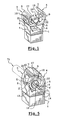
- FIGs 1 and 5 there is shown a collar according to the invention for fixing pipes of two different diameters, one being substantially double the other, the collar being shown in its prepositioning for small diameter and respectively in the open position and in the closed position.
- the collar comprises, in the known manner, a base 1 for attaching the collar to a wall, in particular, by means of a screw or a bolt engaged in a hole 2 (FIG. 4) passing through the base 1, and two flange segments 3 and 4, arranged face to face and mounted articulated on the base 1 by means of hinges 5 arranged at the end of extensions 6 of the base 1.
- the segments 3, 4, hereinafter referred to as first segments, are of rectangular arcuate shape having a concave internal face of curvature corresponding to the external diameter of the pipe to be fixed.
- the hinges 5 connect the extensions 6 to the first segments 3, 4 approximately in their central outer part.
- the ends of the first segments 3, 4 opposite the base 1 are provided with mutual hooking means when the collar is in the closed position ( Figure 5), consisting of a hook tongue 7 on the one (4) of the first segments and a locking projection 8 on the other segment (3).
- the collar described above further comprises means making it possible, by means of the same collar, to fix a pipe having an external diameter less than that corresponding to the first flange segments 3, 4, 1 occurrence a diameter substantially equal to half.
- each first segment (3, 4) is provided with a second flange segment, respectively 3 'and 4', of curvature corresponding to said small diameter.
- the second segments 3 ', 4' have, like the first segments 3, 4, a generally arcuate rectangular shape and are integral, by their small side 11, 12 turned towards the base, the end 13, 14 of the first segments 3 , 4 near the base 1, while the small opposite side, 15, 16 of the segments 3 ', 4' is connected to the segments 3, 4 by a bridge 17, 18.
- the bridges 17, 18 have a shape that is also rectangular, flat and has a thickness greater than that of the segments 3 ', 4' and substantially equal to that of the segments 3, 4.
- the bridges 17, 18 are connected to the second segments 3 ', 4' by a portion of reduced thickness forming a hinge 19 and to the first segments 3, 4 by a portion of reduced thickness forming a hinge 20.
- the hinges 20 are substantially at a mid-distance between the hinges 5 and the ends (7, 8) of the first segments 3, 4.
- the zones of the first segments 3, 4 located between the hinges 11 and 20, on the one hand, and between the hinges 12 and 20, on the other hand, are completely open so as to provide a rectangular arched window respectively. and 22, towards which the second segments 3 ', 4' with their bridging 17, 18 will be pushed for retrieval purposes, as will be seen later, thanks to the elasticity of the material constituting the collar.
- the collar is indeed advantageously made in one piece by molding a suitable plastic material, semi-rigid and allowing a certain elasticity to the various hinges (5, 11, 12, 19 and 20) to play their role.
- the second segments 3 ', 4' are open, their lower edges (base side 1) being parallel and close to each other, while their upper edges (15, 16) are spaced apart by a much greater distance. to the outer diameter of the pipe T1 ( Figure 4), small diameter, to be fixed on the collar.
- the pipe T1 is moved manually along the arrow 23, between the first segments 3, 4 and the second segments 3 ', 4', towards the base 1, after of course fixing the collar on the support concerned.
- the pipe T1 is then firmly gripped and held in place by the bracing effect provided by the bridges 17, 18 pressing the second segments 3 ', 4' against the pipe by bearing on the first segments 3, 4.
- FIG. 11 shows in solid lines the position of retraction of the assemblies 3 ', 17 and 4', 18 and dashed the so-called "small diameter" position of said assemblies.
- the pipe T2 is engaged in the collar (FIG. 9) as in the mode of use of FIG. 4, in the direction (arrow 23) of the base 1, as in the case of a conventional collar presenting the only segments 3, 4.
- Fixing the T2 pipe is also ensured, in this case, in the known manner.
- the ratio between the diameters of the pipes T1, T2 can of course vary to a large extent, the curvature of the segments 3 ', 4' and the length of the bypasses 17, 18 being adapted to the diameter of the smaller pipe of the two.
- the collar of the invention can also naturally accept for each of the two diameters slight variations, plus or minus, the nominal diameter, due to the elasticity of the collar material.
Landscapes
- Engineering & Computer Science (AREA)
- General Engineering & Computer Science (AREA)
- Mechanical Engineering (AREA)
- Clamps And Clips (AREA)
- Supports For Pipes And Cables (AREA)
- Mutual Connection Of Rods And Tubes (AREA)
Claims (5)
- Anpassbare Rohrbefestigungsschelle, mit einer Befestigungsbasis (1), zwei ersten entgegenwirkenden Schellensegmenten (3, 4), die an der Basis über ein Scharnier (5) angelenkt sind, das die Basis mit einem zentralen äußeren Teil jedes Segments verbindet, wobei die Enden der Segmente gegenüber der Basis mit Mitteln (7, 8) für eine gegenseitige Verhakung versehen sind, wobei die ersten Segmente (3, 4) jeweils mit einem zweiten Schellensegment (3', 4') versehen sind, dessen Krümmung stärker als jene der ersten Segmente ist, wobei die zweiten Segmente einander gegenüber angeordnet und an ihren Enden mit den ersten Segmenten über Scharniere (11, 12, 19, 20) verbunden sind und wahlweise die eine oder die andere von zwei stabilen Extrempositionen einnehmen können, wobei sie in einer hiervon in den Raum zwischen den ersten Segmenten (3, 4) vorstehen, derart, dass sie beim Schließen der ersten Segmente eine zweite Schelle mit einem Durchmesser bilden, der kleiner als jener der durch die ersten Segmente gebildeten Schelle ist, und in der anderen hiervon, der so genannten eingezogenen Position, in eine Öffnung (21, 22) geschoben werden können, die in den ersten Segmenten (3, 4) ausgespart ist.
- Rohrschelle nach Anspruch 1, dadurch gekennzeichnet, dass die zweiten Schellensegmente (3', 4') ein Ende (11, 12) besitzen, das mit dem Ende (13, 14) auf Seiten der Basis (1) der ersten Segmente (3, 4) im Wesentlichen übereinstimmt, während das andere Ende (15, 16) über eine verformbare elastische Brücke (17, 18) mit dem ersten Segment (3, 4) in der Umgebung des Endes des ersten Segments gegenüber der Basis verbunden ist, wobei jede Gesamtheit aus zweitem Segment (3', 4') und Brücke (17, 18) in der eingezogenen Position in die Öffnung geschoben werden kann.
- Rohrschelle nach Anspruch 2, dadurch gekennzeichnet, dass die zweiten Segmente (3', 4'), die Brücken (17, 18) und die Öffnungen (21, 22) eine rechtwinklige Form haben und die Brücken (17, 18) an jedem Ende über ein Scharnier (19, 20) mit verringerter Dicke mit den zweiten Segmenten (3', 4') bzw. mit den ersten Segmenten (3, 4) verbunden sind.
- Rohrschelle nach einem der Ansprüche 1 bis 3, dadurch gekennzeichnet, dass sie aus einem geeigneten Kunststoff durch Gießen einteilig hergestellt ist.
- Rohrschelle nach einem der Ansprüche 1 bis 4, dadurch gekennzeichnet, dass die zweiten Segmente in der eingezogenen Position den Raum zwischen den ersten Segmenten (3, 4) vollständig freigeben.
Applications Claiming Priority (2)
| Application Number | Priority Date | Filing Date | Title |
|---|---|---|---|
| FR0104093 | 2001-03-27 | ||
| FR0104093A FR2822919B1 (fr) | 2001-03-27 | 2001-03-27 | Collier de fixation de tuyau adaptable |
Publications (2)
| Publication Number | Publication Date |
|---|---|
| EP1245883A1 EP1245883A1 (de) | 2002-10-02 |
| EP1245883B1 true EP1245883B1 (de) | 2006-09-06 |
Family
ID=8861575
Family Applications (1)
| Application Number | Title | Priority Date | Filing Date |
|---|---|---|---|
| EP02362006A Expired - Lifetime EP1245883B1 (de) | 2001-03-27 | 2002-03-27 | Rohrschelle |
Country Status (6)
| Country | Link |
|---|---|
| EP (1) | EP1245883B1 (de) |
| AT (1) | ATE338905T1 (de) |
| DE (1) | DE60214460T2 (de) |
| ES (1) | ES2272655T3 (de) |
| FR (1) | FR2822919B1 (de) |
| PT (1) | PT1245883E (de) |
Families Citing this family (2)
| Publication number | Priority date | Publication date | Assignee | Title |
|---|---|---|---|---|
| DE102013203098A1 (de) * | 2013-02-26 | 2014-08-28 | Mahle International Gmbh | Befestigungsvorrichtung |
| ES2801224B2 (es) * | 2019-06-27 | 2021-07-12 | Unex Aparellaje Electrico Sl | Dispositivo de sujecion para sujetar un tubo a una pared |
Family Cites Families (6)
| Publication number | Priority date | Publication date | Assignee | Title |
|---|---|---|---|---|
| JPS5064874U (de) * | 1973-10-18 | 1975-06-12 | ||
| CH598528A5 (de) | 1976-03-15 | 1978-04-28 | Egli Fischer & Co | |
| FR2589977B3 (fr) | 1985-11-13 | 1987-12-11 | Trw Carr France Sa | Element de retenue destine a la fixation d'au moins un tuyau ou un cable |
| FR2594903B1 (fr) * | 1986-02-25 | 1988-08-26 | Sonofam | Pince a fermeture automatique perfectionnee |
| DE4123430C1 (de) | 1991-07-15 | 1992-06-17 | Trw United-Carr Gmbh & Co Kg, 6753 Enkenbach-Alsenborn, De | |
| IT1282223B1 (it) | 1995-12-22 | 1998-03-16 | Fischer Italia Sas Di Paolo Mo | Dispositivo fissatubi monolitico in materia plastica |
-
2001
- 2001-03-27 FR FR0104093A patent/FR2822919B1/fr not_active Expired - Fee Related
-
2002
- 2002-03-27 DE DE60214460T patent/DE60214460T2/de not_active Expired - Fee Related
- 2002-03-27 ES ES02362006T patent/ES2272655T3/es not_active Expired - Lifetime
- 2002-03-27 EP EP02362006A patent/EP1245883B1/de not_active Expired - Lifetime
- 2002-03-27 AT AT02362006T patent/ATE338905T1/de not_active IP Right Cessation
- 2002-03-27 PT PT02362006T patent/PT1245883E/pt unknown
Also Published As
| Publication number | Publication date |
|---|---|
| FR2822919B1 (fr) | 2003-12-05 |
| PT1245883E (pt) | 2007-01-31 |
| ATE338905T1 (de) | 2006-09-15 |
| FR2822919A1 (fr) | 2002-10-04 |
| DE60214460T2 (de) | 2007-09-13 |
| ES2272655T3 (es) | 2007-05-01 |
| EP1245883A1 (de) | 2002-10-02 |
| DE60214460D1 (de) | 2006-10-19 |
Similar Documents
| Publication | Publication Date | Title |
|---|---|---|
| FR2613454A1 (fr) | Accouplement tubulaire pour solidariser deux tubes coaxiaux, ou pour verrouiller un tube a demeure | |
| EP0819391A1 (de) | Vorrichtung zur Korrektur der Länge eines Armbandes mit Faltverschluss | |
| FR2534646A1 (fr) | Collier en matiere plastique pour tubes | |
| FR2513328A1 (fr) | Collier de serrage | |
| EP0571247A1 (de) | Schnellkupplung zur Schnappverbindung eines Rohrelements oder einer Montage mehrerer Rohrelemente an einem oder mehreren Rohrenden | |
| BE1008996A3 (fr) | Articulation de couvercle rabattable pour une prise de courant. | |
| FR2762557A1 (fr) | Article comportant deux elements articules l'un par rapport a l'autre | |
| EP1245883B1 (de) | Rohrschelle | |
| WO2020128315A1 (fr) | Charnière de porte pour meuble électrique | |
| EP0216650A1 (de) | Profilverbindungsvorrichtung mit an einer Gelenkverbindung kippbaren Armen | |
| FR2756670A1 (fr) | Connecteur muni d'un levier de verrouillage | |
| EP4480729B1 (de) | Vorrichtung zum spannen eines gegenstandes mit einem gurt | |
| FR2481897A1 (fr) | Bague de serrage pour natte de cheveux | |
| FR2571465A1 (fr) | Collier pour tuyaux | |
| FR2620176A1 (fr) | Collier de serrage muni d'un ruban a boucles fendues, pour la suspension d'un systeme de solidarisation par fermeture | |
| WO2004041685A2 (fr) | Maillon pour tapis de convoyage d'objets quelconques | |
| FR2796674A1 (fr) | Dispositif pour la fixation sur un support, tel qu'une tole, d'une piece, telle qu'une aile en matiere plastique de vehicule automobile | |
| FR2798971A1 (fr) | Agencement de fixation d'un element encastrable dans une ouverture d'emplacement d'une plaque de support | |
| FR2808570A1 (fr) | Ensemble de connexion a verrouillage du type baionnette | |
| EP1367213B1 (de) | Gelenkiger Holmschuh für Leitern | |
| FR3096971A1 (fr) | Dispositif de distribution et récipient équipé dudit dispositif | |
| EP1818459B1 (de) | Vorrichtung zum Verschließen eines Rahmens mit Hilfe einer elastisch am Rahmen verschließbaren Abdeckung | |
| FR2681025A1 (fr) | Balai d'essuie-glace comportant des moyens d'arret longitudinal de la lame d'essuyage. | |
| FR2732083A1 (fr) | Dispositif de connexion a montage simplifie pour assembler deux profiles | |
| CH702623A2 (fr) | Système de raccord à verrou pour lignes de tuyauterie en cas d'expansion et/ou de contraction des tuyaux. |
Legal Events
| Date | Code | Title | Description |
|---|---|---|---|
| PUAI | Public reference made under article 153(3) epc to a published international application that has entered the european phase |
Free format text: ORIGINAL CODE: 0009012 |
|
| AK | Designated contracting states |
Kind code of ref document: A1 Designated state(s): AT BE CH CY DE DK ES FI FR GB GR IE IT LI LU MC NL PT SE TR |
|
| AX | Request for extension of the european patent |
Free format text: AL;LT;LV;MK;RO;SI |
|
| 17P | Request for examination filed |
Effective date: 20030324 |
|
| AKX | Designation fees paid |
Designated state(s): AT BE CH CY DE DK ES FI FR GB GR IE IT LI LU MC NL PT SE TR |
|
| 17Q | First examination report despatched |
Effective date: 20041221 |
|
| GRAP | Despatch of communication of intention to grant a patent |
Free format text: ORIGINAL CODE: EPIDOSNIGR1 |
|
| GRAS | Grant fee paid |
Free format text: ORIGINAL CODE: EPIDOSNIGR3 |
|
| GRAA | (expected) grant |
Free format text: ORIGINAL CODE: 0009210 |
|
| AK | Designated contracting states |
Kind code of ref document: B1 Designated state(s): AT BE CH CY DE DK ES FI FR GB GR IE IT LI LU MC NL PT SE TR |
|
| PG25 | Lapsed in a contracting state [announced via postgrant information from national office to epo] |
Ref country code: IT Free format text: LAPSE BECAUSE OF FAILURE TO SUBMIT A TRANSLATION OF THE DESCRIPTION OR TO PAY THE FEE WITHIN THE PRESCRIBED TIME-LIMIT;WARNING: LAPSES OF ITALIAN PATENTS WITH EFFECTIVE DATE BEFORE 2007 MAY HAVE OCCURRED AT ANY TIME BEFORE 2007. THE CORRECT EFFECTIVE DATE MAY BE DIFFERENT FROM THE ONE RECORDED. Effective date: 20060906 Ref country code: IE Free format text: LAPSE BECAUSE OF FAILURE TO SUBMIT A TRANSLATION OF THE DESCRIPTION OR TO PAY THE FEE WITHIN THE PRESCRIBED TIME-LIMIT Effective date: 20060906 Ref country code: NL Free format text: LAPSE BECAUSE OF FAILURE TO SUBMIT A TRANSLATION OF THE DESCRIPTION OR TO PAY THE FEE WITHIN THE PRESCRIBED TIME-LIMIT Effective date: 20060906 Ref country code: FI Free format text: LAPSE BECAUSE OF FAILURE TO SUBMIT A TRANSLATION OF THE DESCRIPTION OR TO PAY THE FEE WITHIN THE PRESCRIBED TIME-LIMIT Effective date: 20060906 |
|
| REG | Reference to a national code |
Ref country code: GB Ref legal event code: FG4D Free format text: NOT ENGLISH |
|
| REG | Reference to a national code |
Ref country code: CH Ref legal event code: EP |
|
| REG | Reference to a national code |
Ref country code: IE Ref legal event code: FG4D Free format text: LANGUAGE OF EP DOCUMENT: FRENCH |
|
| REF | Corresponds to: |
Ref document number: 60214460 Country of ref document: DE Date of ref document: 20061019 Kind code of ref document: P |
|
| PG25 | Lapsed in a contracting state [announced via postgrant information from national office to epo] |
Ref country code: DK Free format text: LAPSE BECAUSE OF FAILURE TO SUBMIT A TRANSLATION OF THE DESCRIPTION OR TO PAY THE FEE WITHIN THE PRESCRIBED TIME-LIMIT Effective date: 20061206 Ref country code: SE Free format text: LAPSE BECAUSE OF FAILURE TO SUBMIT A TRANSLATION OF THE DESCRIPTION OR TO PAY THE FEE WITHIN THE PRESCRIBED TIME-LIMIT Effective date: 20061206 |
|
| REG | Reference to a national code |
Ref country code: CH Ref legal event code: NV Representative=s name: MICHELI & CIE INGENIEURS-CONSEILS |
|
| GBT | Gb: translation of ep patent filed (gb section 77(6)(a)/1977) |
Effective date: 20061214 |
|
| REG | Reference to a national code |
Ref country code: PT Ref legal event code: SC4A Free format text: AVAILABILITY OF NATIONAL TRANSLATION Effective date: 20061205 |
|
| NLV1 | Nl: lapsed or annulled due to failure to fulfill the requirements of art. 29p and 29m of the patents act | ||
| REG | Reference to a national code |
Ref country code: IE Ref legal event code: FD4D |
|
| PGFP | Annual fee paid to national office [announced via postgrant information from national office to epo] |
Ref country code: MC Payment date: 20070424 Year of fee payment: 7 |
|
| REG | Reference to a national code |
Ref country code: ES Ref legal event code: FG2A Ref document number: 2272655 Country of ref document: ES Kind code of ref document: T3 |
|
| PLBE | No opposition filed within time limit |
Free format text: ORIGINAL CODE: 0009261 |
|
| STAA | Information on the status of an ep patent application or granted ep patent |
Free format text: STATUS: NO OPPOSITION FILED WITHIN TIME LIMIT |
|
| 26N | No opposition filed |
Effective date: 20070607 |
|
| PG25 | Lapsed in a contracting state [announced via postgrant information from national office to epo] |
Ref country code: GR Free format text: LAPSE BECAUSE OF FAILURE TO SUBMIT A TRANSLATION OF THE DESCRIPTION OR TO PAY THE FEE WITHIN THE PRESCRIBED TIME-LIMIT Effective date: 20061207 |
|
| PGFP | Annual fee paid to national office [announced via postgrant information from national office to epo] |
Ref country code: CH Payment date: 20080910 Year of fee payment: 7 Ref country code: DE Payment date: 20080911 Year of fee payment: 7 Ref country code: ES Payment date: 20080924 Year of fee payment: 7 Ref country code: PT Payment date: 20080912 Year of fee payment: 7 |
|
| PGFP | Annual fee paid to national office [announced via postgrant information from national office to epo] |
Ref country code: AT Payment date: 20080924 Year of fee payment: 7 Ref country code: IT Payment date: 20080911 Year of fee payment: 7 |
|
| PGFP | Annual fee paid to national office [announced via postgrant information from national office to epo] |
Ref country code: GB Payment date: 20080910 Year of fee payment: 7 |
|
| PGFP | Annual fee paid to national office [announced via postgrant information from national office to epo] |
Ref country code: BE Payment date: 20080915 Year of fee payment: 7 |
|
| PG25 | Lapsed in a contracting state [announced via postgrant information from national office to epo] |
Ref country code: CY Free format text: LAPSE BECAUSE OF FAILURE TO SUBMIT A TRANSLATION OF THE DESCRIPTION OR TO PAY THE FEE WITHIN THE PRESCRIBED TIME-LIMIT Effective date: 20060906 Ref country code: LU Free format text: LAPSE BECAUSE OF NON-PAYMENT OF DUE FEES Effective date: 20070327 |
|
| BERE | Be: lapsed |
Owner name: LUCCHINA, PASCAL Effective date: 20090331 |
|
| REG | Reference to a national code |
Ref country code: PT Ref legal event code: MM4A Free format text: LAPSE DUE TO NON-PAYMENT OF FEES Effective date: 20090928 |
|
| PG25 | Lapsed in a contracting state [announced via postgrant information from national office to epo] |
Ref country code: PT Free format text: LAPSE BECAUSE OF NON-PAYMENT OF DUE FEES Effective date: 20090928 Ref country code: MC Free format text: LAPSE BECAUSE OF NON-PAYMENT OF DUE FEES Effective date: 20090331 Ref country code: AT Free format text: LAPSE BECAUSE OF NON-PAYMENT OF DUE FEES Effective date: 20090327 |
|
| REG | Reference to a national code |
Ref country code: CH Ref legal event code: PL |
|
| GBPC | Gb: european patent ceased through non-payment of renewal fee |
Effective date: 20090327 |
|
| PG25 | Lapsed in a contracting state [announced via postgrant information from national office to epo] |
Ref country code: CH Free format text: LAPSE BECAUSE OF NON-PAYMENT OF DUE FEES Effective date: 20090331 Ref country code: LI Free format text: LAPSE BECAUSE OF NON-PAYMENT OF DUE FEES Effective date: 20090331 Ref country code: DE Free format text: LAPSE BECAUSE OF NON-PAYMENT OF DUE FEES Effective date: 20091001 |
|
| PG25 | Lapsed in a contracting state [announced via postgrant information from national office to epo] |
Ref country code: BE Free format text: LAPSE BECAUSE OF NON-PAYMENT OF DUE FEES Effective date: 20090331 |
|
| PG25 | Lapsed in a contracting state [announced via postgrant information from national office to epo] |
Ref country code: GB Free format text: LAPSE BECAUSE OF NON-PAYMENT OF DUE FEES Effective date: 20090327 |
|
| PGFP | Annual fee paid to national office [announced via postgrant information from national office to epo] |
Ref country code: FR Payment date: 20091020 Year of fee payment: 8 |
|
| REG | Reference to a national code |
Ref country code: ES Ref legal event code: FD2A Effective date: 20090328 |
|
| PG25 | Lapsed in a contracting state [announced via postgrant information from national office to epo] |
Ref country code: ES Free format text: LAPSE BECAUSE OF NON-PAYMENT OF DUE FEES Effective date: 20090328 |
|
| REG | Reference to a national code |
Ref country code: FR Ref legal event code: ST Effective date: 20101130 |
|
| PG25 | Lapsed in a contracting state [announced via postgrant information from national office to epo] |
Ref country code: FR Free format text: LAPSE BECAUSE OF NON-PAYMENT OF DUE FEES Effective date: 20100331 |
|
| PG25 | Lapsed in a contracting state [announced via postgrant information from national office to epo] |
Ref country code: IT Free format text: LAPSE BECAUSE OF NON-PAYMENT OF DUE FEES Effective date: 20090327 |
|
| PG25 | Lapsed in a contracting state [announced via postgrant information from national office to epo] |
Ref country code: TR Free format text: LAPSE BECAUSE OF NON-PAYMENT OF DUE FEES Effective date: 20100922 |
|
| PGFP | Annual fee paid to national office [announced via postgrant information from national office to epo] |
Ref country code: TR Payment date: 20080916 Year of fee payment: 7 |
|
| PG25 | Lapsed in a contracting state [announced via postgrant information from national office to epo] |
Ref country code: TR Free format text: LAPSE BECAUSE OF NON-PAYMENT OF DUE FEES Effective date: 20090327 |