EP1245944B1 - Cytomètre à écoulement - Google Patents
Cytomètre à écoulement Download PDFInfo
- Publication number
- EP1245944B1 EP1245944B1 EP02006680A EP02006680A EP1245944B1 EP 1245944 B1 EP1245944 B1 EP 1245944B1 EP 02006680 A EP02006680 A EP 02006680A EP 02006680 A EP02006680 A EP 02006680A EP 1245944 B1 EP1245944 B1 EP 1245944B1
- Authority
- EP
- European Patent Office
- Prior art keywords
- flow
- cylindrical lens
- sample
- particles
- lens
- Prior art date
- Legal status (The legal status is an assumption and is not a legal conclusion. Google has not performed a legal analysis and makes no representation as to the accuracy of the status listed.)
- Expired - Lifetime
Links
- 239000002245 particle Substances 0.000 claims description 110
- 239000007788 liquid Substances 0.000 claims description 44
- 210000004027 cell Anatomy 0.000 description 45
- 230000003287 optical effect Effects 0.000 description 28
- 210000000265 leukocyte Anatomy 0.000 description 18
- 210000002700 urine Anatomy 0.000 description 14
- 241000894006 Bacteria Species 0.000 description 12
- 230000005855 radiation Effects 0.000 description 12
- 239000004816 latex Substances 0.000 description 11
- 229920000126 latex Polymers 0.000 description 11
- 239000000463 material Substances 0.000 description 7
- 210000000601 blood cell Anatomy 0.000 description 6
- 230000000052 comparative effect Effects 0.000 description 6
- 230000001965 increasing effect Effects 0.000 description 6
- 210000004369 blood Anatomy 0.000 description 5
- 239000008280 blood Substances 0.000 description 5
- 230000002411 adverse Effects 0.000 description 4
- 230000000694 effects Effects 0.000 description 4
- 210000003743 erythrocyte Anatomy 0.000 description 4
- 230000003247 decreasing effect Effects 0.000 description 3
- 238000001514 detection method Methods 0.000 description 3
- 210000002919 epithelial cell Anatomy 0.000 description 3
- 239000007850 fluorescent dye Substances 0.000 description 3
- 238000000034 method Methods 0.000 description 3
- 238000010186 staining Methods 0.000 description 3
- 210000001772 blood platelet Anatomy 0.000 description 2
- 238000006243 chemical reaction Methods 0.000 description 2
- 238000010586 diagram Methods 0.000 description 2
- 238000010790 dilution Methods 0.000 description 2
- 239000012895 dilution Substances 0.000 description 2
- 239000011521 glass Substances 0.000 description 2
- 238000004458 analytical method Methods 0.000 description 1
- 238000004364 calculation method Methods 0.000 description 1
- 238000010276 construction Methods 0.000 description 1
- 230000001419 dependent effect Effects 0.000 description 1
- 238000009792 diffusion process Methods 0.000 description 1
- 230000002708 enhancing effect Effects 0.000 description 1
- 238000002474 experimental method Methods 0.000 description 1
- 239000012530 fluid Substances 0.000 description 1
- 238000005286 illumination Methods 0.000 description 1
- 238000004519 manufacturing process Methods 0.000 description 1
- 230000035945 sensitivity Effects 0.000 description 1
- 238000007493 shaping process Methods 0.000 description 1
Images




Classifications
-
- G—PHYSICS
- G01—MEASURING; TESTING
- G01N—INVESTIGATING OR ANALYSING MATERIALS BY DETERMINING THEIR CHEMICAL OR PHYSICAL PROPERTIES
- G01N15/00—Investigating characteristics of particles; Investigating permeability, pore-volume or surface-area of porous materials
- G01N15/10—Investigating individual particles
- G01N15/14—Optical investigation techniques, e.g. flow cytometry
- G01N15/1434—Optical arrangements
-
- G—PHYSICS
- G01—MEASURING; TESTING
- G01N—INVESTIGATING OR ANALYSING MATERIALS BY DETERMINING THEIR CHEMICAL OR PHYSICAL PROPERTIES
- G01N21/00—Investigating or analysing materials by the use of optical means, i.e. using sub-millimetre waves, infrared, visible or ultraviolet light
- G01N21/17—Systems in which incident light is modified in accordance with the properties of the material investigated
- G01N21/47—Scattering, i.e. diffuse reflection
- G01N2021/4704—Angular selective
- G01N2021/4707—Forward scatter; Low angle scatter
-
- G—PHYSICS
- G01—MEASURING; TESTING
- G01N—INVESTIGATING OR ANALYSING MATERIALS BY DETERMINING THEIR CHEMICAL OR PHYSICAL PROPERTIES
- G01N2201/00—Features of devices classified in G01N21/00
- G01N2201/06—Illumination; Optics
- G01N2201/061—Sources
- G01N2201/06113—Coherent sources; lasers
- G01N2201/0612—Laser diodes
-
- G—PHYSICS
- G01—MEASURING; TESTING
- G01N—INVESTIGATING OR ANALYSING MATERIALS BY DETERMINING THEIR CHEMICAL OR PHYSICAL PROPERTIES
- G01N33/00—Investigating or analysing materials by specific methods not covered by groups G01N1/00 - G01N31/00
- G01N33/48—Biological material, e.g. blood, urine; Haemocytometers
- G01N33/483—Physical analysis of biological material
- G01N33/487—Physical analysis of biological material of liquid biological material
- G01N33/49—Blood
-
- G—PHYSICS
- G01—MEASURING; TESTING
- G01N—INVESTIGATING OR ANALYSING MATERIALS BY DETERMINING THEIR CHEMICAL OR PHYSICAL PROPERTIES
- G01N33/00—Investigating or analysing materials by specific methods not covered by groups G01N1/00 - G01N31/00
- G01N33/48—Biological material, e.g. blood, urine; Haemocytometers
- G01N33/483—Physical analysis of biological material
- G01N33/487—Physical analysis of biological material of liquid biological material
- G01N33/493—Physical analysis of biological material of liquid biological material urine
Definitions
- the present invention relates to a flow cytometer for optically detecting and analyzing particles such as blood cells in blood, material components contained in urine or the like.
- a flow cytometer is well known as such a particle analyzer.
- the flow cytometer includes a detecting section with a flow cell, a laser and a photoelectric conversion element.
- the flow cell surrounds a sample liquid containing particles to be analyzed with a sheath fluid to converge the sample liquid into a thin flow so that the particles align and pass therethrough.
- the laser irradiates the passing particles with a laser beam to obtain light generated from each particle i.e., optical information.
- the optical information includes scattered light such as forward scattered light, sideward scattered light, backward scattered light, fluorescence or the like. The optical information is suitably selected depending upon an analyzed target.
- the photoelectric conversion element detects the optical information to generate a pulsed electrical signal.
- a waveform of the electrical signal obtained as mentioned above is processed to calculate a parameter representing the characteristics of each particle and the particles to be analyzed are classified and counted based on the parameter.
- an intensity of the light is recognized as a height (peak level) of the signal waveform, and at the same time, a light emitting period (pulse width) is clocked. That is, the above parameter includes the peak level and the pulse width.
- the peak level of the signal of the forward scattered light (hereinafter referred to as a "particle signal”) represents a size of a particle, while the pulse width represents a length of a particle.
- a fluorescent staining represents a staining degree of the nuclear or the like, while the pulse width represents a length of the fluorescent staining portion.
- a histogram is formed based upon the parameter representing the characteristics of each particle or a scattergram showing a distribution of the particles is formed by combining a plurality of parameters, whereby the type or number of the particles contained in the sample is statistically analyzed.
- the above-mentioned flow cytometer generally utilizes a laser diode from which the laser beam is irradiated to the flow cell.
- Fig. 1 is a schematic view showing one example of an optical system in a conventional flow cytometer using a laser diode 1 for a light source.
- a sample liquid T containing particles to be analyzed is supplied from a nozzle 11 into the flow cell 6 in the direction shown by an arrow A.
- a sheath liquid S is supplied to the flow cell 6 for surrounding the supplied sample liquid T, whereby the sample liquid T is converged into a thin sample flow by a hydrodynamic effect. As a result, the sample flow is passed through the flow cell 6 with the particles aligned.
- a radiant laser beam LB emitted from the laser diode 1 is collimated by a collimator lens 3, and then, passes through a cylindrical lens 4 and a condenser lens 5 to form a beam spot at a position R of the flow of the sample liquid T in the flow cell 6.
- the laser diode 1 has inherent features that the laser beam LB is diffusible and has an elliptic cross section.
- the laser beam LB emitted from the laser diode 1 along an optical axis in the direction of Z has radiation angles defined by a large angle ⁇ 1 in the direction of a major diameter of the ellipse, i.e., in the direction of X, and a small angle ⁇ 2 in the direction of a minor diameter of the ellipse, i.e., in the direction of Y.
- Fig. 3 shows a relationship between such an arrangement and an intensity of the detected forward scattered light signal.
- the laser beam LB has such a large radiation angle ⁇ in the direction parallel to the flowing direction of the sample liquid T, that the laser beam LB is partially kicked at upper and lower edges 3a and 3b of the collimator lens 3 to generate stray beams SB1 and SB2. Therefore, the stray beams SB1 and SB2 are focused on focal points BS1 and BS2 above and below a beam spot BS0 focused by a main beam MB in the flow of the sample liquid T.
- signals S1 and S2 hereinafter referred to as "stray beam signal" attributed to the stray beams SB1 and SB2 are detected in addition to a particle signal S0 due to the main beam MB.
- the stray signals S1 and S2 are mistakenly detected as small particle signals, which have a bad influence on the counting and classifying result of the particles to be analyzed. This demerit also applies to each detection of a sideward scattered light signal, backward scattered light signal and fluorescent signal, besides the detection of the forward scattered light signal.
- a threshold value Vth is set to a value so as to detect the particle signal S0 but not the stray beam signals S1 and S2 as shown in Fig. 4. That is, the "threshold value Vth" here is used for selecting the particle signal S0 in a series of signals S1, S0 S2.
- the signal intensity (peak level) VP and the light emitting period (pulse width) PW are calculated based on a part of the signal which exceeds the threshold value Vth.
- the laser diode 1 is provided in the conventional general flow cytometer such that the major diameter of the elliptic section of the emitted laser beam LB is arranged so as to be parallel to the flowing direction of the sample liquid T in the flow cell 6, whereby the above-mentioned merits (1. increasing the amount of light at the beam spot; and 2. decreasing the diameter of the beam spot) can be enjoyed.
- the threshold value Vth is required to be set lower corresponding to the minimum particle signal S0. Therefore, the stray light signals S1 and S2 exceeds the threshold value Vth and are detected by mistake as small-sized particles. This causes a miscount of the particles or gives an adverse affect to the pulse width information of the particle signals.
- urine contains bacteria, red blood cells, white blood cells, epithelial cells, casts or the like, each of which has a various size. Particularly, the bacteria are greatly smaller than the other particles in most cases. In case of detecting these particles, the threshold value Vth for detecting the particle signal S0 should be set lower in order to detect the bacteria.
- the stray beam signals S1 and S2 generated with the particle signal S0 of the white blood cell brings an analysis result as if the bacteria is also detected, although only the white blood cell should originally be detected. Further, the pulse width PW of the particle signal S0 of the white blood cell becomes greater than the original width, whereby the white blood cell may be analyzed as another type.
- the adverse affect of the stray beam signals S1 and S2 is more remarkable in a flow cytometer that is required to detect not only large-sized particles but also small-sized particles.
- a laser diode having a narrower radiation angle is considered to be selected as the laser diode 1 in the optical system shown in Fig. 3 so that the laser beam LB does not impinge on the upper and lower edges 3a and 3b of the collimator lens 3.
- the laser diode generally has a feature that the radiation angle is determined by the wavelength of the laser beam. Further, the wavelength of the laser beam is necessarily determined by the character or kind of a particle to be analyzed. Accordingly, the laser diode having a narrow radiation angle of the laser beam cannot freely be selected.
- a fluorescent staining is performed in advance to blood cells in blood or material components in urine
- obtaining fluorescent information from a fluorescent portion of each particle requires a laser beam having a relatively short wavelength, e.g., 700 nm or less.
- the laser diode generally has a characteristic that, the shorter the wavelength of the emitted laser beam becomes, the wider the radiation angle becomes.
- the radiation angle of the laser beam inevitably increases. Therefore, the laser beam is partially kicked at the upper and lower edges 3a and 3b of the collimator lens 3, thereby causing the problem of generating the stray beam signals SB1 and SB2.
- the collimator lens 3 is required to have a greater NA in order to bring the laser diode 1 close to the collimator lens 3.
- a spherical lens is used as the collimator lens 3
- the lens is required to increase its diameter with the same curvature (i.e., a collimator lens having a greater NA is required to be used).
- a collimator lens having a greater NA is required to be used.
- an aspherical lens as the collimator lens 3. This is because the aspherical lens is unsuited to the collimator lens 3 from the viewpoint of the level of the current lens manufacturing technique.
- EP-A-0 696 731 discloses a flow cytometer comprising a flow cell, a photoelectric detector for receiving light scattered from particles contained in a sample liquid flown in the flow cell, a laser diode for emitting a laser beam, a collimator lens for collimating the emitted laser beam, a first condenser lens for focusing the collimated laser beam, a second condenser lens for condensing the light scattered by particles in the sample liquid and directing the scattered light to the photoelectric detector, and a beam stopper arranged between the flow cell and the second condenser lens for shielding the direct beam passing through the flow cell, wherein the collimating lens and the first condenser lens cooperatively focus the emitted laser beam to form a first beam spot on the sample flow and second beam spot on the beam stopper.
- EP-A-0 564 122 and US-A-4,920,275 disclose flow cytometers comprising cylindrical lens systems for beam shaping.
- the present invention is accomplished in view of the above subjects, and aims to provide a flow cytometer that prevents the generation of the stray beam signals by devising the angle at which the laser diode is arranged, whereby only the particle signal due to the main beam can effectively be detected.
- a flow cytometer includes a flow cell for flowing a sample liquid in a flowing direction to form a sample flow, the sample liquid containing particles to be analyzed, a laser diode radiating a laser beam having an elliptic cross section, a beam collimating section for collimating the laser beam radiated from the laser diode, a beam spot forming section for focusing the collimated beam at the sample flow in the flow cell to form a beam spot, and alight receiving section for receiving light generated from the particles at the beam spot to detect optical information of the particles, wherein the laser diode is arranged such that a minor diameter of the elliptic section of the laser beam is parallel to the sample flow.
- the particles to be analyzed in the present invention mainly include various blood cells contained in blood such as red blood cells, white blood cells and blood plate lets or material components contained in urine such as bacteria, red blood cells, white blood cells, epithelial cell and casts, but are not limited to these.
- the sample liquid is prepared by suitably performing a process such as dilution or staining, in case where the subject to be measured is, for example, a specimen such as blood or urine.
- the flow cell used in the present invention is preferably transparent and has a smooth surface in order to obtain exact optical information from a particle passing therethrough.
- a material such as a glass is used for the flow cell.
- the laser diode used in the present invention is selected among those emitting a laser beam having a wavelength suitable for the character or kind of the particle to be analyzed.
- the beam light collimating section is used to collimate the laser beam emitted from the laser diode.
- a collimator lens is preferably used for the section.
- the beam spot forming section focuses the collimated beam at the sample flow in the flow cell to form a beam spot.
- a condenser lens is preferably used for the section.
- the minor diameter of the elliptic beam spot formed at the sample flow preferably matches to the size of the particle to be analyzed. It is, for example, about 10 microns in the flowing direction of the sample liquid in the case of using a urine specimen as the subject to be measured.
- the light receiving section used in the present invention detects, as optical information, a change in light intensity of scattered light or fluorescene generated when the particle to be analyzed in the sample liquid passes across the beam spot.
- the preferable one photoelectrically converts such optical information into a pulsed electrical signal.
- the light receiving section include a photodiode, phototransistor, photomultiplier tube or the like.
- the wavelength of the laser light emitted from the laser diode may be 700 nm or less in the present invention.
- the sample liquid may be prepared using a urine specimen.
- the particles to be analyzed may be bacteria.
- the flow cytometer of the present invention further comprises a cylindrical lens system, arranged between the light collimating section and the beam spot forming section, for adjusting a beam diameter and a focusing position of the laser beam with respect to a direction perpendicular to the sample flow, a beam stopper for shielding the laser beam passing through the flow cell from the light receiving section, and a condenser lens for converging the light generated from the particles to the light receiving section.
- a cylindrical lens system arranged between the light collimating section and the beam spot forming section, for adjusting a beam diameter and a focusing position of the laser beam with respect to a direction perpendicular to the sample flow
- a beam stopper for shielding the laser beam passing through the flow cell from the light receiving section
- a condenser lens for converging the light generated from the particles to the light receiving section.
- the cylindrical lens system includes a first cylindrical lens for converging the laser beam with respect to the direction perpendicular to the sample flow and a second cylindrical lens for diffusing the laser beam with respect to the direction perpendicular to the sample flow.
- the cylindrical lens system adjusts the laser beam so that the beam spot at the sample flow forms an ellipse having a major diameter perpendicular to the sample flow and the laser beam passing through the flow cell forms an elliptic beam spot on the beam stopper, the elliptic beam spot on the beam stopper having a minor diameter perpendicular to the sample flow.
- the sample flow may be sheathed with a sheath flow in the flow cell, the beam spot at the sample flow having a major diameter substantially equal to a width of the sample and sheath flows and the minor diameter of the elliptic beam spot on the beam stopper is minimized.
- the beam stopper may include of an elongated shielding member extending along the sample flow and arranged at the focusing position of the laser beam adjusted by the cylindrical lens system.
- the first cylindrical lens may include a convex cylindrical lens and the second cylindrical lens may include a concave cylindrical lens.
- Fig. 5 that corresponds to Fig. 3 shows the relationship between the optical system arrangement and the intensity of the forward scattered light signal according to the invention.
- the laser diode 1 is arranged in the present invention such that the minor diameter of the elliptic section of the emitted laser beam is parallel to the flow of the sample liquid in the flow cell. That is, the laser diode 1 is arranged so as to be rotated by an angle of 90 degrees compared to the conventional device.
- the radiation angle ⁇ of the laser beam LB emitted from the laser diode 1 is narrow in the longitudinal direction (flowing direction of the sample liquid) while wide in the lateral direction (direction across the sample liquid).
- This structure prevents that the laser beam LB is partially kicked (truncated) at the upper and lower edges 3a and 3b of the collimator lens 3 to generate the stray beams. Accordingly, no stray beam focuses on any portions adjacent to the beam spot BS0 generated by the main beam MB in the sample flow in the flow cell 6, whereby any stray beam signals are not detected.
- the laser beam LB may be kicked (truncated) at the right and left edges of the collimator lens 3 to generate stray beams.
- these stray beams do not focus on the sample liquid flow, but focus on the right and left portions of the beam spot BS0 (in the direction across the sample flow) out of the sample flow in the flow cell. Therefore, they are not detected as signals.
- Such an arrangement of the laser diode 1 is particularly effective in case where a laser beam having a relatively short wavelength (i.e., a laser beam having a great radiation angle) is required to be used. Specifically, it is effective in the case of using a laser diode that emits a laser beam having a wavelength of 700 nm or less, for example, 635 nm. This is because when this type of laser diode is arranged such that the major diameter of the elliptic section of the emitted laser beam is conventionally parallel to the flowing direction of the sample liquid in the flow cell, the laser beam partially impinges on the upper and lower edges 3a and 3b of the collimator lens 3 to thereby generate stray beams.
- FIG. 6 schematically shows a block diagram of the flow cytometer according to the invention.
- a detecting section 200 that is composed of the optical system explained above detects a pulsed electrical signal from an individual particle to be analyzed.
- This electrical signal is sent to a signal processing section 300 that comprises a circuit for processing the waveform of the pulsed signal obtained from the detecting section 200 to calculate various parameters.
- the calculated parameters include, for example, a peak level, a pulse width or the like. These parameters are calculated by a known peak hold circuit, a counter circuit, and the like.
- the calculated various parameters is sent as particle data to an analyzing section 400 that analyzes the corresponding particle by statistically analyzing the particle data.
- the analyzing section 400 can be made of a microcomputer. A histogram or a scattergram made by combining a plurality of parameters may be formed upon statistically analyzing the particle data.
- the flow cytometer may further include an output section 500 for outputting a result analyzed by the analyzing section 400.
- a display such as a CRT or LCD or a printer such as a laser printer can be used for the outputting section 500.
- embodiment 1 where the flow cytometer of the present invention is adapted to a flow cytometer for analyzing material components in urine.
- a sample liquid containing particles to be analyzed is prepared by performing a dilution or staining process to a urine specimen.
- This apparatus also comprises the detecting section 200, signal processing section 300, analyzing section 400 and outputting section 500 as shown in Fig. 6.
- Figs. 7(a) and 7(b) respectively show a construction of an optical system at the detecting section 200 in the present embodiment.
- a red laser diode (HL 6312G manufactured by Hitachi Seisakusho) is used for the laser diode 1 that is a laser beam source.
- the red laser diode emits a laser beam having a wavelength of 635 nm and a elliptic cross section. Its radiation angle is 31 degrees in the major diameter direction of the elliptic section and 8 degrees in the minor diameter direction.
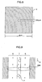
- the flow cell 6 is made of a glass and has a square cross section, one side of which is 4 mm as shown in Fig. 8.
- Fig. 7(a) is a side view of the flow cell 6 in which the optical system is seen from the direction perpendicular to the flowing direction of the sample liquid T.
- the sample liquid T containing the particles to be analyzed is supplied from the nozzle 11 to the flow cell 6 to form a sample flow.
- the laser beam LB emitted from the laser diode 1 is collimated by the collimator lens 3 that is the beam collimating section, and then, passes through the concave cylindrical lens 4 without causing a refraction to focus on a focal point SP1 in the sample flow in the flow cell 6.
- Fig. 7(b) is a top view of the flow cell 6 in which the optical system is seen from the direction parallel to the flowing direction of the sample liquid T.
- the laser beam LB emitted from the laser diode 1 is collimated by the collimator lens 3.
- the collimated laser beam focuses on a second focal point SP2 behind the sample flow in the flow cell 6 by the condenser lens 5 after the beam diameter of the collimated laser beam is enlarged by the light diffusion function of the concave cylindrical lens 4.
- Fig. 9 is a typical view showing a state where the beam spot BS0 is formed on the flow cell 6 when the flow cell is observed from an incident direction of the laser beam LB.
- the minor diameter of the elliptic section matches to the flowing direction of the sample liquid T (direction shown by an arrow A) by the condenser lens 5. This effectively prevents a plurality of particles P from simultaneously passing across the beam spot BS0.
- the concave cylindrical lens 4 allows the major diameter of the elliptic section to match in direction to the direction perpendicular to the flowing direction A of the sample liquid and to substantially match in length to a flow width of the sample liquid T and the sheath liquid S, whereby the particle P which shifts in the direction perpendicular to the flowing direction can fully be detected.
- the minor diameter of the beam spot BS0 is set to be 10 microns by the condenser lens 5 and its major diameter is set to be 220 microns by the concave cylindrical lens 4.
- the irradiation of the laser beam LB produces forward scattered light FS from the particle P that flows through the flow cell 6.
- the forward scattered light FS is converged by a focusing lens 7 on a photodiode 8 to be photoelectrically converted into a pulsed electrical signal.
- the laser beam LB (direct beam) from the condenser lens 5 is cut by a beam stopper 9 while external stray light is cut by a pinhole plate 10 having a pinhole, so that S/N ratio of the electrical signal detected by the photodiode 8 is enhanced.
- the signal detected at the detecting section 200 as described above is transmitted to the signal processing section 300 where a signal waveform of the signal is processed for calculating parameters such as a peak level, pulse width or the like.
- Various parameters calculated as particle data by the signal processing section 300 is transmitted to the analyzing section 400 to be statistically analyzed.
- a scattergram is formed by combining two parameters of the forward scattered light signal, i.e., the peak level and the pulse width, and the particles to be analyzed are counted and classified.
- An analyzed result is outputted by the outputting section 500.
- the data relating to various measuring items are printed out by a printer and the scattergram formed at the analyzing section 400 is displayed by a LCD.
- the present embodiment refers only to the detection of the forward scattered light
- a structure capable of detecting the fluorescence is naturally possible.
- Such a structure can be accomplished by the addition of a light receiving section for detecting a fluorescence signal and other necessary optical systems.
- Known devices can be utilized for the light receiving section and other necessary optical systems.
- a photomultiplier tube is preferably used for the light receiving section.
- a flow cytometer having a conventional structure is used as a comparative example.
- the flow cytometer of the invention and the comparative example are those for analyzing material components in urine. Therefore, the threshold value Vth in each flow cytometer for detecting particles is set low enough to detect bacteria.
- the difference between the flow cytometer of the invention and the comparative example exists in the arranging direction of the laser diode in the detecting section.
- the laser diode 1 is arranged such that the major diameter of the elliptic section of the emitted laser beam LB is parallel to the flowing direction of the sample liquid T in the flow cell 6.
- the laser diode 1 is arranged such that the minor diameter of the elliptic section of the emitted laser beam LB is parallel to the flowing direction of the sample liquid T in the flow cell 6.
- Latex particles each having a diameter of 7 microns are used as particles to be analyzed.
- the latex particles are assumed as white blood cells contained in urine.
- the forward scattered light signal is detected by using these particles for making an observation and comparison of the signal waveform and scattergram.
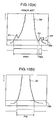
- Fig. 10(a) shows a signal waveform in the forward scattered light signal of the 7 micron-diameter latex particle detected by the comparative example. Observing this waveform, it is found that signals (stray beam signals) S1 and S2 attributed to stray beams appear at the right and left of the signal (particle signal) S0 of the latex particle itself. The stray beam signal S1 appearing at the left of the particle signal S0 results in the calculation of a pulse width PW1 that is different from a pulse width of the latex particle signal S0. If the same state occurs in the case of measuring an actual urine specimen, particles that should originally be detected as white blood cells may mistakenly be detected as particles of another type.
- the stray beam signal S2 appearing at the right of the particle signal S0 is detected as a small-sized particle independent of the 7 micron-diameter latex particle and a peak level Vp or pulse width PW2 corresponding to the small-sized particle is measured. This produces an error in a counting result of the particles. If the same state occurs in the case of measuring an actual urine specimen, an analyzed result may be obtained as if the specimen also contained small-sized particles, e.g., bacteria even through it contains only white blood cells.
- Fig. 10(b) shows a signal waveform in the forward scattered light of the 7 micron-diameter latex particle detected by the flow cytometer of the present invention.
- this waveform any stray beam signals do not occur and only one single pulse signal S0 representative of the 7 micron-diameter latex particle occurs. This shows that the adverse affect to the analyzed result due to the stray beam signal is eliminated and an accurate pulse width PW can be measured.
- Figs. 11(a) and (b) are scattergrams based on the forward scattered light signal of the 7 micron-diameter latex particle, wherein a peak level, i.e., a forward scattered light signal intensity (FSC) is used as a parameter for an ordinate while a pulse width of the forward scattered light signal (FSCW) is used as a parameter for an obscissa.
- FSC forward scattered light signal intensity
- FSCW pulse width of the forward scattered light signal
- the scattergram of in Fig. 11(a) shows a result obtained by the comparative example.
- the particle to be analyzed has a diameter of 7 microns (corresponding to a white blood cell), so that particles should originally be distributed only in the white blood cell area M.
- the particles are distributed in the area other than the white blood cell area M due to the influence of the stray beam signals. That is, the particles detected as large-sized particles from the value of the pulse width influenced by the stray beam signals are distributed at the right side of the white blood cell area M, while the particles detected mistakenly as small-sized particles are distributed in the vicinity of a bacteria area N.
- the scattergram of Fig. 11(b) shows a result obtained by the flow cytometer of the present invention.
- the result is unaffected by any stray beam signals, so that the distribution of particles is concentrated in the white blood cell area M.
- the flow cytometer of the present invention enables to detect only the particle signal generated by the main beam without producing the signal due to stray beam conventionally generated at the edges of the collimator lens. Therefore, more accurate analyzed results can be obtained.
- the adverse affect due to the stray beam signals can be avoided in case where the particles to be analyzed contain small-sized particles such as bacteria. That is, the remarkable effects of the present invention are achieved by the attempt at the optical system.
- Figs. 12(a) and (b) illustrate another embodiment in which the detecting section 200 is modified as follows. That is, the cylindrical concave lens 4 shown in Figs. 7(a) and (b) is replaced with a cylindrical lens system comprising a convex cylindrical lens 4a and a concave cylindrical lens 4b. The other constructional elements are the same as those shown in Figs. 7(a) and (b).
- This modified embodiment has a purpose that the second focal point SP2 shown in Fig. 7(b) is displaced to be present on the beam stopper 9 as shown in Fig. 12(b) for decreasing a width W of the beam stopper 9, whereby a largerer amount of the forward scattered light from the particle can effectively be detected by the photodiode 8.
- the sample liquid containing the particles to be analyzed is ejected from the nozzle 11 to the flow path of the flow cell 6 to form a sample flow of the sample liquid T surrounded by the sheath flow, i.e., the sheath liquid S as shown in Fig. 9.
- the radiant laser beam LB emitted from the laser diode 1 is collimated by the collimator lens 3, and then, passes through the convex cylindrical lens 4a and the concave cylindrical lens 4b without refraction. Thereafter, the laser beam LB focuses on the first focal point SP1 at the sample flow in the flow cell 6, and then, reaches the beam stopper 9 having a length L.
- the laser beam LB is emitted from the laser diode 1 and collimated by the lens 3.
- the collimated beam is reduced and enlarged in beam diameter by refraction functions of the convex cylindrical lens 4a and the concave cylindrical lens 4b, and then, converged at the second focal point SP2 on the beam stopper 9 by the condenser lens 5.
- the beam spot diameter of the laser beam LB formed on the beam stopper 9 is minimized in the direction perpendicular to the flowing direction of the sample liquid T.
- the position of the second focal point SP2 and the major diameter of the beam spot BS0 are independently determined according to focal distances of the convex cylindrical lens 4 and the concave cylindrical lens 5 and their setting positions.
- the laser beam LB forms the elliptic beam spot BS0 having a major diameter of 220 microns and a minor diameter of 10 microns in the sample liquid T in the flow cell 2, and then, passes through the flow cell 2 to be cut by the beam stopper 9.
- the cut laser beam LB forms on the stopper 9 such an elongated elliptic beam spot having a major diameter in the flowing direction of the sample liquid T that the width W of the beam stopper 9 can be extremely reduced.
- the laser beam LB is effectively shielded by the elongated beam stopper 9, whereby the photodiode 8 can receive even low-angle light among the forward scattered light FS.
Landscapes
- Chemical & Material Sciences (AREA)
- Dispersion Chemistry (AREA)
- Physics & Mathematics (AREA)
- Health & Medical Sciences (AREA)
- Life Sciences & Earth Sciences (AREA)
- Analytical Chemistry (AREA)
- Biochemistry (AREA)
- General Health & Medical Sciences (AREA)
- General Physics & Mathematics (AREA)
- Immunology (AREA)
- Pathology (AREA)
- Investigating Or Analysing Biological Materials (AREA)
- Optical Measuring Cells (AREA)
Claims (5)
- Cytomètre à écoulement comprenant :une source optique (1) qui émet un faisceau lumineux (LB) qui est collimaté ;un détecteur photoélectrique (8) ;une chambre d'écoulement (6) pour faire s'écouler un liquide échantillon dans un sens d'écoulement afin de former un écoulement échantillon, le liquide échantillon contenant des particules à analyser ;un système de lentilles cylindriques comprenant une première lentille cylindrique (4a) et une seconde lentille cylindrique (4b) ;la première lentille cylindrique faisant converger le faisceau lumineux collimaté dans une direction perpendiculaire à l'écoulement échantillon et la seconde lentille cylindrique diffusant le faisceau lumineux rendu convergent dans une direction perpendiculaire à l'écoulement échantillon ;une première lentille convergente (5) faisant converger sur la chambre d'écoulement le faisceau lumineux diffusé ;une seconde lentille convergente (7) faisant converger vers le détecteur photoélectrique la lumière générée par les particules ;etun dispositif d'arrêt de faisceau (9) disposé entre la chambre d'écoulement et la seconde lentille convergente pour intercepter un faisceau direct traversant la chambre ;dans lequel le système à lentilles cylindriques règle le faisceau lumineux collimaté de sorte que le faisceau lumineux collimaté forme un premier spot de faisceau (SP1) sur l'écoulement échantillon puis traverse la chambre d'écoulement pour former un second spot de faisceau (SP2) sur le dispositif d'arrêt de faisceau, le premier spot de faisceau ayant la forme d'une ellipse dont le grand diamètre est perpendiculaire à l'écoulement échantillon, le second spot de faisceau ayant la forme d'une ellipse dont le petit diamètre est perpendiculaire à l'écoulement échantillon.
- Cytomètre à écoulement selon la revendication 1, dans lequel l'écoulement échantillon est guidé dans une veine liquide (S) à l'intérieur de la chambre d'écoulement, le premier spot de faisceau ayant un grand diamètre sensiblement égal à une largeur de la veine liquide.
- Cytomètre à écoulement selon l'une quelconque des revendications 1 à 2, dans lequel le dispositif d'arrêt de faisceau (9) comprend un élément d'interception de forme allongée s'étendant le long de l'écoulement échantillon et disposé à la position de focalisation du faisceau lumineux réglé par le système de lentilles cylindriques.
- Cytomètre à écoulement selon l'une quelconque des revendications 1 à 3, dans lequel la première lentille cylindrique (4a) est une lentille cylindrique convexe et la seconde lentille cylindrique (4b) est une lentille cylindrique concave.
- Cytomètre à écoulement selon l'une quelconque des revendications 1 à 4 précédentes, dans lequel la source optique (1) comprend une diode laser émettant un faisceau laser de section elliptique et une lentille de collimation (3) pour collimater le faisceau laser issu de la diode laser, la diode laser étant disposée de sorte que le grand diamètre de la section elliptique soit perpendiculaire à l'écoulement échantillon.
Applications Claiming Priority (4)
| Application Number | Priority Date | Filing Date | Title |
|---|---|---|---|
| JP2001094878A JP4659252B2 (ja) | 2001-03-29 | 2001-03-29 | フローサイトメータ |
| JP2001094878 | 2001-03-29 | ||
| JP2001182085 | 2001-06-15 | ||
| JP2001182085A JP4763159B2 (ja) | 2001-06-15 | 2001-06-15 | フローサイトメータ |
Publications (3)
| Publication Number | Publication Date |
|---|---|
| EP1245944A2 EP1245944A2 (fr) | 2002-10-02 |
| EP1245944A3 EP1245944A3 (fr) | 2002-11-13 |
| EP1245944B1 true EP1245944B1 (fr) | 2007-02-14 |
Family
ID=26612483
Family Applications (1)
| Application Number | Title | Priority Date | Filing Date |
|---|---|---|---|
| EP02006680A Expired - Lifetime EP1245944B1 (fr) | 2001-03-29 | 2002-03-26 | Cytomètre à écoulement |
Country Status (3)
| Country | Link |
|---|---|
| US (1) | US6713019B2 (fr) |
| EP (1) | EP1245944B1 (fr) |
| DE (1) | DE60218074T2 (fr) |
Families Citing this family (78)
| Publication number | Priority date | Publication date | Assignee | Title |
|---|---|---|---|---|
| JP4323571B2 (ja) | 1997-01-31 | 2009-09-02 | エックスワイ, インコーポレイテッド | 光学装置 |
| US6149867A (en) | 1997-12-31 | 2000-11-21 | Xy, Inc. | Sheath fluids and collection systems for sex-specific cytometer sorting of sperm |
| US6071689A (en) | 1997-12-31 | 2000-06-06 | Xy, Inc. | System for improving yield of sexed embryos in mammals |
| WO1999060397A1 (fr) | 1998-05-18 | 1999-11-25 | University Of Washington | Cartouche d'analyse liquide |
| US6830729B1 (en) | 1998-05-18 | 2004-12-14 | University Of Washington | Sample analysis instrument |
| ES2296398T3 (es) | 1998-07-30 | 2008-04-16 | Xy, Inc. | Sistema de inseminacion equina artificial no quirurgica. |
| US7208265B1 (en) | 1999-11-24 | 2007-04-24 | Xy, Inc. | Method of cryopreserving selected sperm cells |
| EP2258173A3 (fr) | 2000-05-09 | 2012-06-13 | Xy, Llc | Populations de spermatozoïdes portant un chromosome X et un chromosome Y de grande pureté |
| CA2822983C (fr) | 2000-11-29 | 2017-05-09 | Xy, Llc | Systeme de dissociation de spermatozoides congeles-decongeles porteurs d'un chromosome x de ceux porteurs d'un chromosome y |
| US7713687B2 (en) | 2000-11-29 | 2010-05-11 | Xy, Inc. | System to separate frozen-thawed spermatozoa into x-chromosome bearing and y-chromosome bearing populations |
| EP1542529A4 (fr) * | 2002-07-22 | 2006-08-09 | Xy Inc | Systeme de traitement de cellule spermatique |
| US8211629B2 (en) | 2002-08-01 | 2012-07-03 | Xy, Llc | Low pressure sperm cell separation system |
| US8486618B2 (en) | 2002-08-01 | 2013-07-16 | Xy, Llc | Heterogeneous inseminate system |
| CA2534394C (fr) | 2002-08-15 | 2013-01-08 | Xy, Inc. | Cytometre a flux haute resolution |
| US7169548B2 (en) | 2002-09-13 | 2007-01-30 | Xy, Inc. | Sperm cell processing and preservation systems |
| DK2959774T3 (da) | 2003-03-28 | 2019-05-13 | Inguran Llc | Fremgangsmåde til kryokonservering af sædceller |
| WO2004104178A2 (fr) | 2003-05-15 | 2004-12-02 | Xy, Inc. | Tri efficace de cellules haploides pour systemes de cytometrie en flux |
| US7468789B2 (en) * | 2004-02-05 | 2008-12-23 | Advanced Analytical Technologies, Inc. | Flow cytometer for rapid bacteria detection |
| US8705040B2 (en) * | 2004-03-06 | 2014-04-22 | Michael Trainer | Methods and apparatus for determining particle characteristics by measuring scattered light |
| EP2260854A1 (fr) | 2004-03-29 | 2010-12-15 | Inguran, LLC | Suspensions de sperme pour trier des populations enrichies contenant les chromosomes X ou Y |
| AU2005266930B2 (en) | 2004-07-22 | 2010-09-16 | Inguran, Llc | Process for enriching a population of sperm cells |
| US7340957B2 (en) | 2004-07-29 | 2008-03-11 | Los Alamos National Security, Llc | Ultrasonic analyte concentration and application in flow cytometry |
| US7465560B2 (en) * | 2004-11-30 | 2008-12-16 | Purdue Research Foundation | System and method for rapid detection and characterization of bacterial colonies using forward light scattering |
| US7110192B2 (en) * | 2005-01-12 | 2006-09-19 | Dako Denmark A/S | System and method for a composite lens for a flow cytometer |
| WO2006103920A1 (fr) * | 2005-03-29 | 2006-10-05 | Sysmex Corporation | Procede de differenciation du cancer, des cellules atypiques et analyseur cellulaire |
| US7113266B1 (en) | 2005-03-30 | 2006-09-26 | Beckman Coulter, Inc. | Flow cytometer for differentiating small particles in suspension |
| US7616311B2 (en) * | 2005-05-02 | 2009-11-10 | Jmar Llc | Systems and methods for a multiple angle light scattering (MALS) instrument having two-dimensional detector array |
| US7618770B2 (en) | 2005-07-29 | 2009-11-17 | Xy, Inc. | Methods and apparatus for reducing protein content in sperm cell extenders |
| WO2007022641A1 (fr) | 2005-08-25 | 2007-03-01 | Institut National D'optique | Analyse par cytometrie en flux a travers une fibre optique |
| US7324724B2 (en) * | 2005-10-21 | 2008-01-29 | Institut National D'optique | Optical fiber devices using component insertion |
| US8050730B2 (en) | 2005-12-23 | 2011-11-01 | Shenzhen Mindray Bio-Medical Electrics Co., Ltd. | Method and apparatus for eliminating interference in pulse oxygen measurement |
| CN101000306B (zh) * | 2006-01-09 | 2010-11-17 | 深圳迈瑞生物医疗电子股份有限公司 | 细胞分析仪 |
| MX2008011364A (es) | 2006-03-10 | 2009-02-11 | Saryna Biotechnologies Llc D B | Dispositivo de suministro de muestras de alta velocidad. |
| JP4817442B2 (ja) * | 2006-07-31 | 2011-11-16 | シスメックス株式会社 | 粒子分析装置用光学系、及びそれを用いた粒子分析装置 |
| EP2069121B1 (fr) * | 2006-09-25 | 2011-07-27 | Basf Se | Procédé destiné à produire de manière continue des particules polymères absorbant l'eau |
| CN101153868B (zh) * | 2006-09-30 | 2012-05-30 | 深圳迈瑞生物医疗电子股份有限公司 | 流式细胞分析仪 |
| US7835000B2 (en) | 2006-11-03 | 2010-11-16 | Los Alamos National Security, Llc | System and method for measuring particles in a sample stream of a flow cytometer or the like |
| US8787633B2 (en) * | 2007-01-16 | 2014-07-22 | Purdue Research Foundation | System and method of organism identification |
| EP2479552B1 (fr) * | 2007-04-02 | 2015-09-02 | Acoustic Cytometry Systems, Inc. | Procédés pour l'analyse amplifiée de cellules et particules focalisées par un champ acoustique |
| US7837040B2 (en) * | 2007-04-09 | 2010-11-23 | Los Alamos National Security, Llc | Acoustic concentration of particles in fluid flow |
| US8083068B2 (en) | 2007-04-09 | 2011-12-27 | Los Alamos National Security, Llc | Apparatus for separating particles utilizing engineered acoustic contrast capture particles |
| US7800742B2 (en) * | 2007-10-03 | 2010-09-21 | Sysmex Corporation | Cell analyzer and cell analyzing method |
| US8263407B2 (en) | 2007-10-24 | 2012-09-11 | Los Alamos National Security, Llc | Method for non-contact particle manipulation and control of particle spacing along an axis |
| US8528406B2 (en) * | 2007-10-24 | 2013-09-10 | Los Alamos National Security, LLP | Method for non-contact particle manipulation and control of particle spacing along an axis |
| EP2204643B1 (fr) | 2007-10-29 | 2019-08-21 | Sysmex Corporation | Appareil d'analyse cellulaire et procédé d'analyse cellulaire |
| JP4556996B2 (ja) * | 2007-12-13 | 2010-10-06 | ソニー株式会社 | 光学的検出方法 |
| US8266951B2 (en) | 2007-12-19 | 2012-09-18 | Los Alamos National Security, Llc | Particle analysis in an acoustic cytometer |
| US8714014B2 (en) * | 2008-01-16 | 2014-05-06 | Life Technologies Corporation | System and method for acoustic focusing hardware and implementations |
| US8995493B2 (en) | 2009-02-17 | 2015-03-31 | Trilumina Corp. | Microlenses for multibeam arrays of optoelectronic devices for high frequency operation |
| US8995485B2 (en) | 2009-02-17 | 2015-03-31 | Trilumina Corp. | High brightness pulsed VCSEL sources |
| US20130223846A1 (en) | 2009-02-17 | 2013-08-29 | Trilumina Corporation | High speed free-space optical communications |
| US10244181B2 (en) | 2009-02-17 | 2019-03-26 | Trilumina Corp. | Compact multi-zone infrared laser illuminator |
| US10038304B2 (en) | 2009-02-17 | 2018-07-31 | Trilumina Corp. | Laser arrays for variable optical properties |
| CA2756045A1 (fr) * | 2009-03-20 | 2010-09-23 | Biorad Laboratories, Inc. | Cytometrie en flux avec microscopie et imagerie en fluorescence multicolore codee par balayage lineaire en serie |
| EP2526401A4 (fr) | 2010-01-18 | 2015-04-22 | Handyem Inc | Analyse de cytométrie à écoulement à travers une fibre optique |
| KR20120074558A (ko) * | 2010-12-28 | 2012-07-06 | 삼성전자주식회사 | 미세입자 검출장치 |
| US8761486B2 (en) * | 2011-02-22 | 2014-06-24 | Bio-Rad Laboratories, Inc. | Line scan cytometry systems and methods |
| US11095365B2 (en) | 2011-08-26 | 2021-08-17 | Lumentum Operations Llc | Wide-angle illuminator module |
| BR112014004612A2 (pt) * | 2011-08-26 | 2017-05-16 | Trilumina Corp | comunicações ópticas em espaço livre em alta velocidade |
| WO2013145836A1 (fr) * | 2012-03-30 | 2013-10-03 | ソニー株式会社 | Dispositif de mesure optique de micropuce et procédé d'ajustement de position optique pour ledit dispositif |
| ES2987440T3 (es) | 2012-05-30 | 2024-11-14 | Iris Int Inc | Citómetro de flujo |
| US9746412B2 (en) | 2012-05-30 | 2017-08-29 | Iris International, Inc. | Flow cytometer |
| CN102680379B (zh) * | 2012-05-31 | 2015-01-21 | 长春迪瑞医疗科技股份有限公司 | 一种使用偶次高次非球面激光整形系统的白细胞分类计数仪 |
| JP2014062822A (ja) * | 2012-09-21 | 2014-04-10 | Sony Corp | 微小粒子分析装置及び微小粒子分析方法 |
| CN102938534A (zh) * | 2012-11-09 | 2013-02-20 | 维林光电(苏州)有限公司 | 一种半导体激光器及其产生高质量和高稳定光束的方法 |
| JP5877810B2 (ja) * | 2013-03-26 | 2016-03-08 | シスメックス株式会社 | 粒子分析装置、粒子分析装置用光学系および粒子分析装置用レンズ |
| US9857284B1 (en) * | 2013-07-15 | 2018-01-02 | Stratedigm, Inc. | Method and apparatus for detection and measurement of particles with a wide dynamic range of measurement |
| EP3077790B1 (fr) | 2013-12-04 | 2021-10-27 | Iris International, Inc. | Cytomètre en flux |
| JP6116502B2 (ja) | 2014-02-28 | 2017-04-19 | シスメックス株式会社 | 検体分析装置および検体分析方法 |
| JP6539023B2 (ja) * | 2014-07-18 | 2019-07-03 | 株式会社堀場製作所 | 粒子分析装置 |
| JP6352713B2 (ja) * | 2014-07-22 | 2018-07-04 | シスメックス株式会社 | フローサイトメータ、粒子分析装置およびフローサイトメトリー法 |
| CN104833659B (zh) * | 2014-12-19 | 2017-05-24 | 武汉沃亿生物有限公司 | 一种生物样品断层显微成像系统 |
| CN106198359B (zh) * | 2016-07-05 | 2019-08-06 | 迪瑞医疗科技股份有限公司 | 一种使用积分球的白细胞分类计数仪用光学系统 |
| US11215545B2 (en) * | 2017-06-14 | 2022-01-04 | Cytochip Inc. | Devices and methods for cell analysis |
| CA3211350A1 (fr) * | 2018-03-30 | 2019-10-03 | Idexx Laboratories, Inc. | Cytometre en flux, ensemble optique laser associe et procedes d'assemblage associes |
| CN115917292B (zh) | 2020-06-17 | 2023-08-25 | Idexx实验室公司 | 流式细胞仪及其激光光学组件 |
| CN111855542A (zh) * | 2020-07-02 | 2020-10-30 | 江南大学 | 一种快速细胞计数装置及计数方法 |
| EP4724787A1 (fr) * | 2023-06-06 | 2026-04-15 | Beckman Coulter, Inc. | Détection de nanoparticules |
Family Cites Families (9)
| Publication number | Priority date | Publication date | Assignee | Title |
|---|---|---|---|---|
| US4636075A (en) * | 1984-08-22 | 1987-01-13 | Particle Measuring Systems, Inc. | Particle measurement utilizing orthogonally polarized components of a laser beam |
| JPS63253237A (ja) * | 1987-04-10 | 1988-10-20 | Omron Tateisi Electronics Co | 流れ式粒子分析装置 |
| US4920275A (en) * | 1988-12-30 | 1990-04-24 | Canon Kabushiki Kaisha | Particle measuring device with elliptically-shaped scanning beam |
| DE69118429T2 (de) * | 1990-01-26 | 1996-09-12 | Canon Kk | Verfahren zur Messung einer Spezies unter Verwendung von Fluoreszenzlicht |
| JP3070968B2 (ja) * | 1991-05-14 | 2000-07-31 | シスメックス株式会社 | 尿中の細胞分析用試薬及び方法 |
| JP3187129B2 (ja) * | 1992-04-01 | 2001-07-11 | シスメックス株式会社 | 粒子分析装置 |
| JP3355038B2 (ja) * | 1994-08-03 | 2002-12-09 | シスメックス株式会社 | 白血球分類方法 |
| JP3375203B2 (ja) * | 1994-08-08 | 2003-02-10 | シスメックス株式会社 | 細胞分析装置 |
| JP3308441B2 (ja) * | 1995-12-19 | 2002-07-29 | シスメックス株式会社 | 尿中有形成分分析装置 |
-
2002
- 2002-03-26 DE DE60218074T patent/DE60218074T2/de not_active Expired - Lifetime
- 2002-03-26 EP EP02006680A patent/EP1245944B1/fr not_active Expired - Lifetime
- 2002-03-27 US US10/106,062 patent/US6713019B2/en not_active Expired - Lifetime
Also Published As
| Publication number | Publication date |
|---|---|
| US20020141902A1 (en) | 2002-10-03 |
| DE60218074D1 (de) | 2007-03-29 |
| EP1245944A2 (fr) | 2002-10-02 |
| DE60218074T2 (de) | 2008-02-07 |
| EP1245944A3 (fr) | 2002-11-13 |
| US6713019B2 (en) | 2004-03-30 |
Similar Documents
| Publication | Publication Date | Title |
|---|---|---|
| US6713019B2 (en) | Flow cytometer | |
| US7561267B2 (en) | Flow cytometer | |
| US7113266B1 (en) | Flow cytometer for differentiating small particles in suspension | |
| US7385682B2 (en) | Cytometer | |
| US4999513A (en) | Particle measuring apparatus | |
| US7075647B2 (en) | Back-scatter detection in flow cytometers | |
| US7876436B2 (en) | Irradiation unit for a flow-cytometry-based analytical instrument and analytical instrument including the same | |
| US7715006B2 (en) | Optical system for a particle analyzer and particle analyzer using same | |
| US10018550B2 (en) | System and method for analyzing blood cell | |
| US12240770B2 (en) | Systems and method for correction of positionally dependent electromagnetic radiation detected from objects within a fluid column | |
| US11898951B2 (en) | Forward scattered light detection system, flow cytometer and method for measuring cell diameter | |
| US11204310B2 (en) | Optical flow cytometer for epi fluorescence measurement | |
| US11442001B2 (en) | Light collection from objects within a fluid column | |
| JP4763159B2 (ja) | フローサイトメータ | |
| JP4659252B2 (ja) | フローサイトメータ |
Legal Events
| Date | Code | Title | Description |
|---|---|---|---|
| PUAI | Public reference made under article 153(3) epc to a published international application that has entered the european phase |
Free format text: ORIGINAL CODE: 0009012 |
|
| PUAL | Search report despatched |
Free format text: ORIGINAL CODE: 0009013 |
|
| AK | Designated contracting states |
Kind code of ref document: A2 Designated state(s): AT BE CH CY DE DK ES FI FR GB GR IE IT LI LU MC NL PT SE TR |
|
| AX | Request for extension of the european patent |
Free format text: AL;LT;LV;MK;RO;SI |
|
| AK | Designated contracting states |
Kind code of ref document: A3 Designated state(s): AT BE CH CY DE DK ES FI FR GB GR IE IT LI LU MC NL PT SE TR |
|
| AX | Request for extension of the european patent |
Free format text: AL;LT;LV;MK;RO;SI |
|
| 17P | Request for examination filed |
Effective date: 20030312 |
|
| AKX | Designation fees paid |
Designated state(s): DE FR GB IT |
|
| 17Q | First examination report despatched |
Effective date: 20040311 |
|
| GRAP | Despatch of communication of intention to grant a patent |
Free format text: ORIGINAL CODE: EPIDOSNIGR1 |
|
| GRAS | Grant fee paid |
Free format text: ORIGINAL CODE: EPIDOSNIGR3 |
|
| GRAA | (expected) grant |
Free format text: ORIGINAL CODE: 0009210 |
|
| AK | Designated contracting states |
Kind code of ref document: B1 Designated state(s): DE FR GB IT |
|
| REG | Reference to a national code |
Ref country code: GB Ref legal event code: FG4D |
|
| REF | Corresponds to: |
Ref document number: 60218074 Country of ref document: DE Date of ref document: 20070329 Kind code of ref document: P |
|
| ET | Fr: translation filed | ||
| PLBE | No opposition filed within time limit |
Free format text: ORIGINAL CODE: 0009261 |
|
| STAA | Information on the status of an ep patent application or granted ep patent |
Free format text: STATUS: NO OPPOSITION FILED WITHIN TIME LIMIT |
|
| 26N | No opposition filed |
Effective date: 20071115 |
|
| REG | Reference to a national code |
Ref country code: FR Ref legal event code: PLFP Year of fee payment: 14 |
|
| REG | Reference to a national code |
Ref country code: FR Ref legal event code: PLFP Year of fee payment: 15 |
|
| PGFP | Annual fee paid to national office [announced via postgrant information from national office to epo] |
Ref country code: IT Payment date: 20160324 Year of fee payment: 15 |
|
| REG | Reference to a national code |
Ref country code: FR Ref legal event code: PLFP Year of fee payment: 16 |
|
| REG | Reference to a national code |
Ref country code: FR Ref legal event code: PLFP Year of fee payment: 17 |
|
| PG25 | Lapsed in a contracting state [announced via postgrant information from national office to epo] |
Ref country code: IT Free format text: LAPSE BECAUSE OF NON-PAYMENT OF DUE FEES Effective date: 20170326 |
|
| PGFP | Annual fee paid to national office [announced via postgrant information from national office to epo] |
Ref country code: DE Payment date: 20180313 Year of fee payment: 17 Ref country code: GB Payment date: 20180321 Year of fee payment: 17 |
|
| PGFP | Annual fee paid to national office [announced via postgrant information from national office to epo] |
Ref country code: FR Payment date: 20180223 Year of fee payment: 17 |
|
| REG | Reference to a national code |
Ref country code: DE Ref legal event code: R119 Ref document number: 60218074 Country of ref document: DE |
|
| GBPC | Gb: european patent ceased through non-payment of renewal fee |
Effective date: 20190326 |
|
| PG25 | Lapsed in a contracting state [announced via postgrant information from national office to epo] |
Ref country code: DE Free format text: LAPSE BECAUSE OF NON-PAYMENT OF DUE FEES Effective date: 20191001 Ref country code: GB Free format text: LAPSE BECAUSE OF NON-PAYMENT OF DUE FEES Effective date: 20190326 |
|
| PG25 | Lapsed in a contracting state [announced via postgrant information from national office to epo] |
Ref country code: FR Free format text: LAPSE BECAUSE OF NON-PAYMENT OF DUE FEES Effective date: 20190331 |