EP1245974A1 - Mach-Zehnder-Interferometer und Verfahren zu dessen Herstellung - Google Patents
Mach-Zehnder-Interferometer und Verfahren zu dessen Herstellung Download PDFInfo
- Publication number
- EP1245974A1 EP1245974A1 EP01108125A EP01108125A EP1245974A1 EP 1245974 A1 EP1245974 A1 EP 1245974A1 EP 01108125 A EP01108125 A EP 01108125A EP 01108125 A EP01108125 A EP 01108125A EP 1245974 A1 EP1245974 A1 EP 1245974A1
- Authority
- EP
- European Patent Office
- Prior art keywords
- fibers
- optical
- contact section
- mach
- tapering
- Prior art date
- Legal status (The legal status is an assumption and is not a legal conclusion. Google has not performed a legal analysis and makes no representation as to the accuracy of the status listed.)
- Withdrawn
Links
- 238000004519 manufacturing process Methods 0.000 title claims abstract description 14
- 238000000034 method Methods 0.000 title claims description 54
- 239000000835 fiber Substances 0.000 claims abstract description 189
- 230000003287 optical effect Effects 0.000 claims abstract description 175
- 230000008878 coupling Effects 0.000 claims abstract description 32
- 238000010168 coupling process Methods 0.000 claims abstract description 32
- 238000005859 coupling reaction Methods 0.000 claims abstract description 32
- 239000013307 optical fiber Substances 0.000 claims abstract description 13
- 230000001902 propagating effect Effects 0.000 claims description 17
- 238000012544 monitoring process Methods 0.000 claims description 15
- 239000000463 material Substances 0.000 claims description 10
- 238000010438 heat treatment Methods 0.000 claims description 7
- 230000008569 process Effects 0.000 description 16
- 238000005516 engineering process Methods 0.000 description 12
- 230000004927 fusion Effects 0.000 description 10
- 238000009826 distribution Methods 0.000 description 8
- 230000003993 interaction Effects 0.000 description 7
- 230000000694 effects Effects 0.000 description 6
- 229920005989 resin Polymers 0.000 description 6
- 239000011347 resin Substances 0.000 description 6
- 239000011248 coating agent Substances 0.000 description 5
- 238000000576 coating method Methods 0.000 description 5
- 230000004044 response Effects 0.000 description 5
- 239000000758 substrate Substances 0.000 description 5
- 238000010586 diagram Methods 0.000 description 4
- 230000003595 spectral effect Effects 0.000 description 4
- 229920001187 thermosetting polymer Polymers 0.000 description 4
- 230000015572 biosynthetic process Effects 0.000 description 3
- 238000005253 cladding Methods 0.000 description 3
- 230000006353 environmental stress Effects 0.000 description 3
- 230000001681 protective effect Effects 0.000 description 3
- VYPSYNLAJGMNEJ-UHFFFAOYSA-N Silicium dioxide Chemical compound O=[Si]=O VYPSYNLAJGMNEJ-UHFFFAOYSA-N 0.000 description 2
- 230000008901 benefit Effects 0.000 description 2
- 238000006073 displacement reaction Methods 0.000 description 2
- 230000002427 irreversible effect Effects 0.000 description 2
- BASFCYQUMIYNBI-UHFFFAOYSA-N platinum Chemical compound [Pt] BASFCYQUMIYNBI-UHFFFAOYSA-N 0.000 description 2
- 230000035882 stress Effects 0.000 description 2
- NIXOWILDQLNWCW-UHFFFAOYSA-M Acrylate Chemical compound [O-]C(=O)C=C NIXOWILDQLNWCW-UHFFFAOYSA-M 0.000 description 1
- 239000006244 Medium Thermal Substances 0.000 description 1
- 238000004026 adhesive bonding Methods 0.000 description 1
- 230000005540 biological transmission Effects 0.000 description 1
- 230000008859 change Effects 0.000 description 1
- 238000007796 conventional method Methods 0.000 description 1
- 239000003822 epoxy resin Substances 0.000 description 1
- 239000011521 glass Substances 0.000 description 1
- 230000006698 induction Effects 0.000 description 1
- 238000002955 isolation Methods 0.000 description 1
- GQYHUHYESMUTHG-UHFFFAOYSA-N lithium niobate Chemical compound [Li+].[O-][Nb](=O)=O GQYHUHYESMUTHG-UHFFFAOYSA-N 0.000 description 1
- 230000010355 oscillation Effects 0.000 description 1
- 238000004806 packaging method and process Methods 0.000 description 1
- 238000005192 partition Methods 0.000 description 1
- 230000010363 phase shift Effects 0.000 description 1
- 239000004033 plastic Substances 0.000 description 1
- 239000006223 plastic coating Substances 0.000 description 1
- 229910052697 platinum Inorganic materials 0.000 description 1
- 230000010287 polarization Effects 0.000 description 1
- 229920000647 polyepoxide Polymers 0.000 description 1
- 239000010453 quartz Substances 0.000 description 1
- 230000005855 radiation Effects 0.000 description 1
- 239000004065 semiconductor Substances 0.000 description 1
Images

Classifications
-
- G—PHYSICS
- G02—OPTICS
- G02F—OPTICAL DEVICES OR ARRANGEMENTS FOR THE CONTROL OF LIGHT BY MODIFICATION OF THE OPTICAL PROPERTIES OF THE MEDIA OF THE ELEMENTS INVOLVED THEREIN; NON-LINEAR OPTICS; FREQUENCY-CHANGING OF LIGHT; OPTICAL LOGIC ELEMENTS; OPTICAL ANALOGUE/DIGITAL CONVERTERS
- G02F1/00—Devices or arrangements for the control of the intensity, colour, phase, polarisation or direction of light arriving from an independent light source, e.g. switching, gating or modulating; Non-linear optics
- G02F1/29—Devices or arrangements for the control of the intensity, colour, phase, polarisation or direction of light arriving from an independent light source, e.g. switching, gating or modulating; Non-linear optics for the control of the position or the direction of light beams, i.e. deflection
- G02F1/31—Digital deflection, i.e. optical switching
- G02F1/313—Digital deflection, i.e. optical switching in an optical waveguide structure
- G02F1/3136—Digital deflection, i.e. optical switching in an optical waveguide structure of interferometric switch type
-
- G—PHYSICS
- G02—OPTICS
- G02B—OPTICAL ELEMENTS, SYSTEMS OR APPARATUS
- G02B6/00—Light guides; Structural details of arrangements comprising light guides and other optical elements, e.g. couplings
- G02B6/24—Coupling light guides
- G02B6/26—Optical coupling means
- G02B6/28—Optical coupling means having data bus means, i.e. plural waveguides interconnected and providing an inherently bidirectional system by mixing and splitting signals
- G02B6/2804—Optical coupling means having data bus means, i.e. plural waveguides interconnected and providing an inherently bidirectional system by mixing and splitting signals forming multipart couplers without wavelength selective elements, e.g. "T" couplers, star couplers
- G02B6/2821—Optical coupling means having data bus means, i.e. plural waveguides interconnected and providing an inherently bidirectional system by mixing and splitting signals forming multipart couplers without wavelength selective elements, e.g. "T" couplers, star couplers using lateral coupling between contiguous fibres to split or combine optical signals
- G02B6/2835—Optical coupling means having data bus means, i.e. plural waveguides interconnected and providing an inherently bidirectional system by mixing and splitting signals forming multipart couplers without wavelength selective elements, e.g. "T" couplers, star couplers using lateral coupling between contiguous fibres to split or combine optical signals formed or shaped by thermal treatment, e.g. couplers
-
- G—PHYSICS
- G02—OPTICS
- G02F—OPTICAL DEVICES OR ARRANGEMENTS FOR THE CONTROL OF LIGHT BY MODIFICATION OF THE OPTICAL PROPERTIES OF THE MEDIA OF THE ELEMENTS INVOLVED THEREIN; NON-LINEAR OPTICS; FREQUENCY-CHANGING OF LIGHT; OPTICAL LOGIC ELEMENTS; OPTICAL ANALOGUE/DIGITAL CONVERTERS
- G02F1/00—Devices or arrangements for the control of the intensity, colour, phase, polarisation or direction of light arriving from an independent light source, e.g. switching, gating or modulating; Non-linear optics
- G02F1/01—Devices or arrangements for the control of the intensity, colour, phase, polarisation or direction of light arriving from an independent light source, e.g. switching, gating or modulating; Non-linear optics for the control of the intensity, phase, polarisation or colour
- G02F1/21—Devices or arrangements for the control of the intensity, colour, phase, polarisation or direction of light arriving from an independent light source, e.g. switching, gating or modulating; Non-linear optics for the control of the intensity, phase, polarisation or colour by interference
- G02F1/225—Devices or arrangements for the control of the intensity, colour, phase, polarisation or direction of light arriving from an independent light source, e.g. switching, gating or modulating; Non-linear optics for the control of the intensity, phase, polarisation or colour by interference in an optical waveguide structure
- G02F1/2252—Devices or arrangements for the control of the intensity, colour, phase, polarisation or direction of light arriving from an independent light source, e.g. switching, gating or modulating; Non-linear optics for the control of the intensity, phase, polarisation or colour by interference in an optical waveguide structure in optical fibres
-
- G—PHYSICS
- G02—OPTICS
- G02B—OPTICAL ELEMENTS, SYSTEMS OR APPARATUS
- G02B6/00—Light guides; Structural details of arrangements comprising light guides and other optical elements, e.g. couplings
- G02B6/24—Coupling light guides
- G02B6/26—Optical coupling means
- G02B6/264—Optical coupling means with optical elements between opposed fibre ends which perform a function other than beam splitting
- G02B6/266—Optical coupling means with optical elements between opposed fibre ends which perform a function other than beam splitting the optical element being an attenuator
-
- G—PHYSICS
- G02—OPTICS
- G02F—OPTICAL DEVICES OR ARRANGEMENTS FOR THE CONTROL OF LIGHT BY MODIFICATION OF THE OPTICAL PROPERTIES OF THE MEDIA OF THE ELEMENTS INVOLVED THEREIN; NON-LINEAR OPTICS; FREQUENCY-CHANGING OF LIGHT; OPTICAL LOGIC ELEMENTS; OPTICAL ANALOGUE/DIGITAL CONVERTERS
- G02F1/00—Devices or arrangements for the control of the intensity, colour, phase, polarisation or direction of light arriving from an independent light source, e.g. switching, gating or modulating; Non-linear optics
- G02F1/01—Devices or arrangements for the control of the intensity, colour, phase, polarisation or direction of light arriving from an independent light source, e.g. switching, gating or modulating; Non-linear optics for the control of the intensity, phase, polarisation or colour
- G02F1/0128—Devices or arrangements for the control of the intensity, colour, phase, polarisation or direction of light arriving from an independent light source, e.g. switching, gating or modulating; Non-linear optics for the control of the intensity, phase, polarisation or colour based on electro-mechanical, magneto-mechanical, elasto-optic effects
- G02F1/0131—Devices or arrangements for the control of the intensity, colour, phase, polarisation or direction of light arriving from an independent light source, e.g. switching, gating or modulating; Non-linear optics for the control of the intensity, phase, polarisation or colour based on electro-mechanical, magneto-mechanical, elasto-optic effects based on photo-elastic effects, e.g. mechanically induced birefringence
- G02F1/0134—Devices or arrangements for the control of the intensity, colour, phase, polarisation or direction of light arriving from an independent light source, e.g. switching, gating or modulating; Non-linear optics for the control of the intensity, phase, polarisation or colour based on electro-mechanical, magneto-mechanical, elasto-optic effects based on photo-elastic effects, e.g. mechanically induced birefringence in optical waveguides
-
- G—PHYSICS
- G02—OPTICS
- G02F—OPTICAL DEVICES OR ARRANGEMENTS FOR THE CONTROL OF LIGHT BY MODIFICATION OF THE OPTICAL PROPERTIES OF THE MEDIA OF THE ELEMENTS INVOLVED THEREIN; NON-LINEAR OPTICS; FREQUENCY-CHANGING OF LIGHT; OPTICAL LOGIC ELEMENTS; OPTICAL ANALOGUE/DIGITAL CONVERTERS
- G02F1/00—Devices or arrangements for the control of the intensity, colour, phase, polarisation or direction of light arriving from an independent light source, e.g. switching, gating or modulating; Non-linear optics
- G02F1/01—Devices or arrangements for the control of the intensity, colour, phase, polarisation or direction of light arriving from an independent light source, e.g. switching, gating or modulating; Non-linear optics for the control of the intensity, phase, polarisation or colour
- G02F1/0147—Devices or arrangements for the control of the intensity, colour, phase, polarisation or direction of light arriving from an independent light source, e.g. switching, gating or modulating; Non-linear optics for the control of the intensity, phase, polarisation or colour based on thermo-optic effects
Definitions
- the present invention concerns a method of making a Mach-Zehnder interferometer, particularly in all-fiber technology, and a related Mach-Zehnder interferometer.
- a Mach-Zehnder Interferometer is a device having at least one optical input, two interferometer arms, at least one optical output and two optical couplings, capable of working as optical power splitters, one between the at least one input and the interferometer arms, the other between the interferometer arms and the at least one output.
- Typical MZIs have two inputs and two outputs (“2x2 MZI”), albeit simpler MZIs can have only one input and one output.
- a 2x2 MZI using single-mode optical guides comprises a first pair of optical guides and a second pair of optical guides.
- the optical guides can be optical fibers or integrated guides.
- the device is bi-directional or reciprocal: the first pair of optical guides and the second pair of optical guides can be used alternately as inputs, respectively outputs, or as outputs, respectively inputs, the device operation being nominally identical in the two cases.
- the first pair of optical guides and the second pair of optical guides are coupled to respective optical couplings, acting as optical power splitters.
- the two optical couplings are coupled to each other by means of two optical guide segments, forming the interferometer arms.
- Each of the interferometer arms has an optical length equal to ⁇ L, where ⁇ is the propagation constant of the propagating mode and L is the physical length of the arm.
- the propagation constant ⁇ is in turn equal to (2 ⁇ / ⁇ )*n, where ⁇ is the wavelength of the propagating mode and n is the refraction index of the propagating mode.
- the two arms can have equal or different optical lengths: in the former case the interferometer is said to be balanced, while in the latter it is said to be unbalanced.
- each optical power splitter splits in two nominally equal parts the optical power received on either one of the two inputs thereof. More generally, the optical splitting ratios of the two optical power splitters can be different from 50%, and also be different from each other.
- optical power splitting ratios of the two optical power splitters and the degree of unbalance of the interferometer arms it is at least nominally possible to obtain on the device outputs, by interferometric effect, any optical power splitting ratio from 0% to 100% of the optical power supplied to the device through any one of the two inputs, independently of the operating optical band of the optical power splitters.
- a balanced MZI is capable of transferring on one of the two outputs thereof the whole optical power received trough one of the two inputs thereof, on a nominally infinite optical band.
- an unbalanced MZI in which the difference between the arm optical lengths is equal to ⁇ at a predetermined wavelength is capable of transferring the whole optical power from one input to one output thereof only at said predetermined wavelength.
- the unbalance between the two arms only determines an output attenuation of optical power.
- MZIs are devices widely used in many applications in optics, thanks to the structural simplicity thereof and because they are formed by elements that can easily be practically implemented in optical guides, such as integrated wave guides or optical fibers, exploiting a single technology.
- MZIs are particularly attractive in several applications, both in the field of telecommunication and in the field of sensors.
- MZIs allow for example to vary the optical power splitting ratio on their outputs in dependence of a difference in optical length of the two interferometer arms.
- a difference in optical length between the two arms can be deliberately induced, for example by means of a suitable control, to obtain a variable attenuator or an optical switch. Otherwise, this effect can be exploited to detect or measure characteristic properties of materials or structures which, once inserted in one of the two interferometer arms, can induce variations in the optical length thereof.
- MZIs can be practically fabricated by means of two main technologies.
- a first technology makes use of planar technology applied to substrate materials such as lithium niobate, semiconductor materials, silica glass, with integrated planar optical guides.
- MZIs fabricated by this technology are however difficult to interface with most of the existing transmission lines.
- a second technology also referred to as all-fiber technology, allows fabricating MZIs directly from two optical fibers, properly coupled to each other to form the optical power splitters.
- This second technology is particularly interesting in applications requiring low optical losses.
- techniques are known providing for acting directly on the fibers which permit to vary the optical length of the arms quite efficiently.
- structures including Bragg gratings are more conveniently implemented in all-fiber MZIs than in planar technology MZIs, because of the lower losses and also because the techniques of formation of Bragg gratings in fibers are more mature than those currently available for planar guides.
- a conventional technique for fabricating all-fiber MZIs generally provides for bringing two fibers close to each other for a sufficiently long section thereof, from which the external plastic coating has previously been removed; forming the first optical coupling by fusing together the fiber claddings and stretching the fibers in a first region of said section; forming the second optical coupling by fusing together the fiber claddings and stretching the fibers in a second region of said section, properly spaced apart from the first region.
- FBT Fused Biconical Tapering
- the two fibers remain physically independent from each other in the region between the two optical couplings, that is, in the region of the two interferometer arms.
- the fibers can be for example individually coated with a thin layer of high resistivity material to form a device tuneable by thermo-optic effect, such as the electrically tuneable MZI described in GB-A-2191013, or a piezo-electric squeezer can be mounted on one of the two fibers to induce, by piezo-electric deformation of the fiber, a differential phase shift between radiations of different polarization, such as the switchable polarisation splitter described in GB-A-2211956.
- EP-A-0989423 describes a way to optimize the spectral response of a fused fiber MZI with Bragg gratings in the interferometer arms and optical couplings formed as asymmetric fused couplers, by properly modifying the fibers in the regions of the optical couplings.
- US 5,479,546 describes an all-fiber MZI with two tapered biconical couplers, in which one of the arms has a tapered optical fiber region.
- the MZI is thus rendered unbalanced and the spectral response thereof can be controlled.
- US 6,031,948 describes an all-fiber MZI.
- the MZI is properly unbalanced so to have a spectral response suitable for separating DWDM channels when cascading several MZIs.
- WO 98/29769 describes that using all-fiber MZI made of special fibers it is possible to obtain non-linear switches responsive to an optical command.
- MZIs fabricated by means of the known implementation of the all-fiber technology are in general affected by the problem that the devices thus obtained are not structurally monolithic.
- the two fibers constituting the MZI are in fact fused together only in the regions of the two optical power splitters, while in the region of the interferometer arms the two fibers remain physically distinct.
- the device operating point strongly depends on the differential optical length of the interferometer arms, and such a differential optical length in turn strongly depends on thermal gradients, vibrations and other environmental stresses on the fibers.
- the differential optical length of the interferometer arms is thus heavily affected by thermal gradients, vibrations and other environmental stresses that impact to a different extent on the two fibers.
- optical path gradients may arise on one of the two fibers more than on the other fiber, due to undesired effects such as environmental stresses (temperature gradients, for example), vibrations etc.
- the stability problem is exacerbated when Bragg gratings are formed in both the interferometer arms: in this case the above criticality adds up to the already critical stability of the Bragg gratings.
- GB 2178846 discloses a MZI comprising a single optical fiber incorporating two coaxially disposed waveguides, e.g. an inner rod waveguide and a surrounding tube waveguide, and having a pair of axially spaced tapered regions forming couplers between the two waveguides at said regions. A MZI is then obtained by submitting the structure to two successive tapering operations.
- a MZI fabrication technique in which starting from two optic fibers, two optical couplers are formed by a fused biconical tapering technique, with the two optic fibers crossing over at a very small angle so that intermediate fiber sections constituting the interferometer arms are closely adjacent each other. These sections are then barely fused together to form a joint.
- the joint has a figure-of-eight cross-section, so there is very little interference at the intermediate fiber sections between optical signal components propagating along the fibers. However the joint is sufficient to secure the fibers against vibration.
- the intermediate fiber sections constituting the interferometer arms are rigidly supported by some other means.
- the step of barely fusing together the portions of the two fibers forming the interferometer arms is carried out only after the optical couplers have been formed.
- This requires an extremely critical control of this process step, not to induce undesired, substantially irreversible mismatches in the optical path of the interferometer arms.
- EP-A-0204492 a MZI fabrication process is reported in which, starting from a pair of fibers, a first and a second optical couplers are formed by fiber heating and stretching the fibers. Then, both arms of the interferometer are coated with a thin layer of high resistive material, electrodes connected to the ends of the layer on one arms, and the device is encapsulated in a protective medium comprising a thermosetting resin.
- thermosetting resin protective medium thermal and mechanical stability is conferred thereto.
- the use of resins in the region of the interferometer arms may induce irreversible undesired mismatches in the arm optical length, due to the shrinkage of the fibers during the curing of the resin.
- MZIs fabricated by the known techniques are affected by the problem that the interaction efficiency of an external control signal with the interferometer arms is quite limited. This is a consequence of the fact that in the region of the interferometer arms the initial optical structure of the two fibers is, at the best, substantially unaltered.
- optical fibers are fabricated in such a way as to confine the oscillation mode substantially at the centre of the fiber, and have a cladding more than ten times thicker than the mode dimension. This makes very difficult to affect from outside the optical signal propagating through the fiber.
- thermosetting resin protective medium exacerbates the problem of a low efficiency of interaction with an external control signal.
- the Applicant has devised a fabrication method that allows for obtaining substantially monolithic all-fiber MZIs, in which before the steps of forming the optical splitters/couplers, the optical fibers are fused together in the portion thereof which in the final device will form the interferometer arms. Additionally, in said portion the fibers are tapered to provide a prescribed degree of optical coupling between the fibers in the region of the interferometer arms: this is for example achieved by monitoring the degree of optical coupling between the fibers during the fusing and tapering step, and terminating it when the prescribed degree of optical coupling is reached.
- a first aspect of the invention relates to a method of making an all-fiber Mach-Zehnder interferometer comprising at least two optical fibers.
- the method is characterized by comprising the steps of:
- said first portion is located mid way between the second and third portions.
- the first portion of the contact region may substantially extend from the second portion to the third portion.
- the fusing together and tapering the fibers precedes the forming at least two optical couplers.
- the fusing together and tapering the fibers comprises stretching the fibers in the first portion of the contact section.
- the fusing and tapering the first and second fibers comprises softening without stretching the fibers in the first portion of the contact section, and then simultaneously fusing together and stretching the fibers.
- said softening the fibers comprises heating the fibers in the first portion of the contact section up to a first prescribed temperature
- said simultaneously fusing together and stretching the fibers comprises heating the fibers in the first portion of the contact section up to a second prescribed temperature, higher than the first prescribed temperature
- the first prescribed temperature is approximately equal to 1470 °C
- the second prescribed temperature is approximately equal to 1580 °C.
- the fusing together and tapering the fibers in the first portion of the contact section comprises monitoring a degree of optical coupling between the fibers and terminating the tapering when a monitored degree of optical coupling reaches a prescribed value.
- the prescribed value of the monitored optical coupling is not higher than approximately 3/1000, preferably 1/1000.
- said monitoring the degree of optical coupling comprises injecting into one of the fibers an optical signal at a monitoring wavelength higher than an operating wavelength of the Mach-Zehnder interferometer, and monitoring a coupled optical power at said wavelength.
- the monitoring wavelength is approximately equal to 1550 nm and the operating wavelength is approximately equal to 1310 nm.
- the optical couplers are formed by means of a fused biconical tapering technique.
- the method may further comprise securing the fibers to a support in two securing locations, substantially at two ends of said contact section.
- a second aspect of the invention relates to an all-fiber Mach-Zehnder interferometer comprising at least two optical fibers in reciprocal contact relationship in a contact section thereof and at least two optical couplers respectively formed in a first and second portions of said contact section, characterized in that the fibers are fused together and tapered in at least a third portion, intermediate the first and second portions of the contact section.
- said third portion is located mid way between the second and third portion of the contact section.
- the third portion of the contact section may substantially extend from the first second portion to the second third portion of the contact section.
- the fibers are secured to a support in two securing locations, substantially at two ends of said contact section.
- a third aspect of the invention relates to an optical device characterised in that it comprises:
- said control element is a thermo-optical actuator.
- thermo-optical actuator is a resistive material film applied externally to the fiber.
- said control element is a piezoelectric actuator.
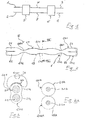
- the MZI comprises a first pair of optical guides 1, 2 and a second pair of optical guides 3, 4.
- the first pair of optical guides 1, 2 and the second pair of optical guides are optically coupled to a first optical coupler 5 and a second optical coupler 6, respectively.
- two optical guide sections 7, 8 form respective arms of the interferometer.
- the device is substantially bi-directional (i.e., reciprocal): the first pair of optical guides 1, 2 and the second pair of optical guides 3, 4 can alternately act as interferometer inputs, respectively outputs, or vice versa.
- the device can be optimised for working in one direction only, for example with the first pair of optical guides 1, 2 working as inputs and the second pair of optical guides 3, 4 working as outputs.
- the schematic diagram of Figure 1 is descriptive of a MZI independently of the technology adopted for the fabrication thereof.
- Figure 2 schematically shows in elevation an all-fiber MZI according to an embodiment of the invention.
- the device comprises a first fiber 201 and a second fiber 202, aligned and close to each other in a reciprocal contact relationship.
- First sections 21, 22 of the first and second fibers 201, 202 forms the first pair of optical guides 1, 2.
- Second sections 23, 24 of the first and second fibers 201, 202 form the second pair of optical guides 3, 4.
- the first and second optical couplers 5, 6 are formed by respective first and second fused together and tapered sections 251, 252 and 261, 262 of the first and second fibers 201, 202.
- Intermediate sections 27, 28 of the first and second fibers 201, 202, respectively, extending between the first and second fused and tapered sections 251, 252 and 261, 262 correspond to the optical guide sections 7, 8 of Figure 1 and form the interferometer arms.
- the first and second fibers 201, 202 are fused together and tapered at least in respective portions 291, 292 of the intermediate sections 27, 28.
- the fiber portions 291, 292 extend across a plane III-III transversal to the fibers 201, 202.
- plane III-III is placed substantially mid way along the intermediate fiber sections 27, 28.
- the third sections 291, 292 are centered around plane III-III.
- Figure 3 shows a cross-sectional view along plane III-III of the MZI of Figure 2. Shaded circular regions 31, 32 schematically show the distribution of the optical power associated with a propagating mode inside the interferometer arms.
- Figure 3A shows a similar cross-sectional view of a conventional all-fiber MZI comprised of two fibers 201A, 202A and wherein, in the respective fiber sections 27A, 28A forming the interferometer arms, the fibers 201A, 202A are in simple contact relationship; as in Figure 3, shaded circular regions 31A, 32A show the optical power distribution of the propagating mode.
- the width of the optical power distribution 31, 32 of the propagating mode compared to the external dimension of the fibers is substantially higher in the MZI of Figure 2 than in the conventional MZI. This widening is a consequence of the guiding characteristics of the fiber tapering.
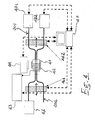
- FIG. 4 schematically shows an apparatus which, albeit experimental, is suitable for implementing the method of the invention.
- the apparatus comprises a micro-furnace 41 for fusing the fibers.
- the micro-furnace 41 is preferably made of platinum and has a length of approximately 13 mm.
- an induction coil 42 is associated therewith and is supplied by a radio frequency generator 43.
- a pyrometer 44 is also operatively coupled to the micro-furnace 41, so as to externally measure the temperature thereof.
- the apparatus also comprises two drives 461, 462, adapted for translating towards and away from the micro-furnace 41, for stretching the fibers.
- An optical signal generator 47 is provided to inject an optical signal into one of the two fibers 201, 202, for example fiber 201, from one end thereof.
- Two power meters 481, 482 are provided to measure the optical power at the outputs of the fibers.
- a two-channel power meter can be used: in this case, numerals 481 and 482 designate the two channels of the power meter.
- the radio-frequency generator 43, the pyrometer 44, the drives 461, 462 and the power meters 481, 482 are operatively connected to and controlled by a control unit 49, for example a personal computer.
- Two fibers 201, 202 for example step-index fibers of the type SMF 28 produced by Corning, are initially subjected to a step of stripping of their plastic (typically acrylate) coating 50 for respective sections thereof, for example of the length of approximately 40 mm each.
- plastic typically acrylate
- the two fibers 201, 202 are then placed inside the micro-furnace 41, and are brought in physical contact to each other, for example submitting them to a twisting of 360°. Then, the fibers are attached to the drives 461, 462.
- the following steps provide for fusing together and tapering the fibers in a substantially central region of the fiber sections from which the coating has been removed.
- one of the two fibers for example fiber 201, is coupled at one end thereof, chosen to act as an optical input, to the optical signal generator 47; the latter is tuned to generate an optical signal at a nominal wavelength of 1550 nm.
- the opposite ends of the fibers, chosen to act as optical outputs, are coupled to the power meters 481, 482.
- the radio-frequency generator 43 is then activated to heat the micro-furnace 41.
- the fibers are thus submitted to a process of fusion without stretching: the micro-furnace temperature is brought to approximately 1470 °C and kept to this value for a prescribed period of time, for example 120 seconds, sufficient to soften the fibers, while the drives are kept deactivated.
- a process of fusion and simultaneous stretching of fibers follows: the micro-furnace temperature is raised, preferably to approximately 1580 °C, and the drives 461, 462 are activated to stretch the fibers.
- the two drives move away from each other at a prescribed speed; preferably, each drive is moved away from the micro-furnace at a speed of approximately 0.33 mm/sec.
- the control unit 49 monitors the optical power measured by the power meters 481, 482: as the fibers are fused together and stretched, they become more and more tapered.
- the tapering causes optical power of the mode propagating through fiber 201 to be transferred by optical coupling to fiber 202.
- the process is terminated when the monitored degree of coupling between the fibers reaches a prescribed value, preferably comprised between 0 and 3/1000, for example approximately 1/1000.
- a prescribed value preferably comprised between 0 and 3/1000, for example approximately 1/1000.
- the Applicant has experimentally found that, with the cited fibers and experimental conditions, this value of optical power coupling corresponds to approximately 8 mm of stretching.
- the following steps provides for forming one of the two optical couplers 5, 6, for example optical coupler 5.
- the two drives 461, 462 are moved jointly in a same sense to bring in the fusion zone a new region of the fiber sections from which the coating 50 has been stripped off.
- the drives are moved jointly towards the right of Figure 4, so as to bring in the fusion zone a new fiber region situated at the left of the fused and tapered fiber portions 291, 292.
- the new fiber region is located at approximately 4 mm from the fused and tapered portions 291, 292.
- the optical signal generator is tuned to generate an optical signal at a nominal wavelength of 1310 nm.
- the radio-frequency generator is activated and the fibers are submitted to a process of fusion without stretching: the micro-furnace temperature is brought to approximately 1490 °C and kept to this value for a prescribed period of time, for example 120 seconds, sufficient to soften the fibers, while the drives are kept deactivated.
- a process of fusion and simultaneous stretching of the fibers follows: the micro-furnace temperature is raised, preferably to approximately 1600 °C, and the drives 461, 462 are activated to stretch the fibers. To this purpose, the two drives move away from each other at a prescribed speed; preferably, each drive is moved away the micro-furnace 41 at a speed of approximately 0.32 mm/sec.
- control unit 49 monitors the optical power measured by the power meters 481, 482. The process is terminated when the degree of coupling between the fibers reaches a prescribed value, for example nominally 50/100 (in the practice, a value in the range 45/100 to 55/100 is suitable).
- a prescribed value for example nominally 50/100 (in the practice, a value in the range 45/100 to 55/100 is suitable).
- the Applicant has experimentally found that, with the cited experimental conditions, this value of optical power coupling corresponds to approximately 12 mm of stretching.
- the following steps provides for forming the other of the two optical couplers, in the example optical coupler 6. These steps are substantially similar to those just described for the formation of the first optical coupler.
- the two drives are moved jointly in a same sense to bring in the fusion zone a new region of the fiber sections from which the coating 50 has been stripped off.
- the drives are moved jointly towards the left of Figure 4, so as to bring in the fusion zone a new region of the fibers situated at the right of the fused and tapered portions 291, 292.
- the drives are moved so as to displace the fibers of approximately 13.5 mm compared to the previous position.
- the optical signal generator again generates an optical signal at a nominal wavelength of 1310 nm.
- the radio-frequency generator is then activated and the fibers are submitted to a process of fusion without stretching: the micro-furnace temperature is brought to approximately 1490 °C and kept to this value for a prescribed period of time, for example 120 seconds, sufficient to soften the fibers, while the drives are kept deactivated.
- a process of fusion and simultaneous stretching of the fibers follows: the micro-furnace temperature is raised, preferably to approximately 1600 °C, and the drives 461, 462 are activated to stretch the fibers. To this purpose, the two drives move away from each other at a prescribed speed; preferably, each drive is moved away from the micro-furnace at a speed of approximately 0.32 mm/sec.
- the control unit 49 monitors the optical power measured by the power meters 481, 482. The process is terminated when the monitored degree of coupling between the fibers reaches a prescribed value, for example nominally 50/100 (practically, the value can be in the range 55/100 to 45/100, depending on the degree of coupling reached during the formation of the first optical coupler).
- a prescribed value for example nominally 50/100 (practically, the value can be in the range 55/100 to 45/100, depending on the degree of coupling reached during the formation of the first optical coupler).
- this value of optical power coupling corresponds to approximately 12.2 mm of stretching.
- a support substrate 60 ( Figure 6), preferably made of quartz, is introduced into the micro-furnace.
- Thermosetting epoxy resin is added in prescribed attachment locations of the structure. Preferably, such locations are two locations 61, 62 situated substantially at the two boundaries of the fiber sections from which the coating 50 has previously been stripped off.
- the resin is then cured at 120 °C.
- the optical signal generator is tuned on a wavelength (1310 nm) corresponding to the operating wavelength of the MZI.
- the optical signal generator is tuned on a wavelength (1550 nm) higher than the MZI operating wavelength.
- the MZI obtained by means of the method according to the invention has a monolithic structure, since the two fibers form a substantially single block. Thanks to this, the MZI is substantially not affected by stresses (temperature, vibrations etc.) causing undesired differential optical path variations of the interferometer arms.
- this step can be terminated when the optical coupling between the fibers is still substantially negligible (for example, of the order of 1/1000 at a longer wavelength). In this way, the interferometric properties of the final device are not altered.
- the optical power distribution of the propagating mode on a transversal cross-section of the fibers in the region of the interferometer arms it can be seen that the optical power distribution of the propagating mode is wide compared to the external dimension of the fibers.
- the width of the optical power distribution of the propagating mode allows for increasing the efficiency of the interaction between the propagating mode and an external signal.
- one of the two arm of the interferometer may comprise a control element act to obtain a differential phase displacement of 180°.
- control element may cause a thermo-optical effect; the interferometer arms shall be subjected to a differential heating, so as to obtain said differential phase displacement of 180°.
- control element is a thermo-optical actuator and comprise a resistive material film 33 applied externally to the fiber 201. Said resistive material film is supplied with a electrical control voltage in order to heat said fiber 201.
- control element heat laterally only one of the two fibers.
- the heat distribution inside the tapered fiber structure is much more efficient than inside the non-tapered one shown in Figure 3A, so that a lower control voltage is to be supplied to the resistive material film 33 and a better dynamic response is achieved.
- Other type of control element for controlling the MZI can however be used, such as for example control elements based on the piezo-electric effect.
- the step of fusing together and tapering the fibers in the region of the interferometer arms is carried out before the steps of forming the optical couplers.
- the structure is already substantially monolithic, that is it has already been rendered stable. This makes the fabrication method sufficiently reproducible. It is in fact to be observed that during the step of fusing and tapering the fibers for forming the last optical coupler, a stable monitoring of the optical power is important to be able to stop the process at the desired prescribed point. At this time the structure is in fact already interferometric in nature, and any differential stress, e.g. mechanical, possibly induced during the fiber tapering could make the power monitoring unstable.
- a further advantage of the MZI according to the invention resides in the simplified attachment thereof to a support substrate. Conventionally, after the fabrication of the MZI is completed the device is attached by gluing to a stiff support substrate, so as to confer mechanical stability and to protect the structure. Thanks to the fact that the MZI according to the invention is substantially monolithic, it is sufficient to provide only two attachment locations to the support, as depicted in Figure 6.
- the fibers could be fused and tapered in more than one portion along the interferometer arms. For example, this could be useful should the MZI be very long, with arms longer than approximately 9 mm.
Landscapes
- Physics & Mathematics (AREA)
- Nonlinear Science (AREA)
- General Physics & Mathematics (AREA)
- Optics & Photonics (AREA)
- Mechanical Light Control Or Optical Switches (AREA)
- Instruments For Measurement Of Length By Optical Means (AREA)
Priority Applications (4)
| Application Number | Priority Date | Filing Date | Title |
|---|---|---|---|
| EP01108125A EP1245974A1 (de) | 2001-03-30 | 2001-03-30 | Mach-Zehnder-Interferometer und Verfahren zu dessen Herstellung |
| PCT/EP2002/003078 WO2002079833A1 (en) | 2001-03-30 | 2002-03-19 | Mach-zehnder interferometer and method of manufacture thereof |
| EP02737888A EP1423740A1 (de) | 2001-03-30 | 2002-03-19 | Mach-zehnder-interferometer und verfahren zu dessen herstellung |
| US10/113,447 US6862386B2 (en) | 2001-03-30 | 2002-03-28 | Method of making a Mach-Zehnder interferometer, and related device |
Applications Claiming Priority (1)
| Application Number | Priority Date | Filing Date | Title |
|---|---|---|---|
| EP01108125A EP1245974A1 (de) | 2001-03-30 | 2001-03-30 | Mach-Zehnder-Interferometer und Verfahren zu dessen Herstellung |
Publications (1)
| Publication Number | Publication Date |
|---|---|
| EP1245974A1 true EP1245974A1 (de) | 2002-10-02 |
Family
ID=8177001
Family Applications (2)
| Application Number | Title | Priority Date | Filing Date |
|---|---|---|---|
| EP01108125A Withdrawn EP1245974A1 (de) | 2001-03-30 | 2001-03-30 | Mach-Zehnder-Interferometer und Verfahren zu dessen Herstellung |
| EP02737888A Withdrawn EP1423740A1 (de) | 2001-03-30 | 2002-03-19 | Mach-zehnder-interferometer und verfahren zu dessen herstellung |
Family Applications After (1)
| Application Number | Title | Priority Date | Filing Date |
|---|---|---|---|
| EP02737888A Withdrawn EP1423740A1 (de) | 2001-03-30 | 2002-03-19 | Mach-zehnder-interferometer und verfahren zu dessen herstellung |
Country Status (2)
| Country | Link |
|---|---|
| EP (2) | EP1245974A1 (de) |
| WO (1) | WO2002079833A1 (de) |
Families Citing this family (1)
| Publication number | Priority date | Publication date | Assignee | Title |
|---|---|---|---|---|
| CN118443150B (zh) * | 2024-04-12 | 2025-03-11 | 南通大学 | 一种微双臂mzi模式监测器及其制备方法和工作原理 |
Citations (5)
| Publication number | Priority date | Publication date | Assignee | Title |
|---|---|---|---|---|
| GB2163549A (en) * | 1984-08-22 | 1986-02-26 | Gen Electric Plc | Mach Zehnder interferometer |
| GB2191013A (en) * | 1986-05-27 | 1987-12-02 | Gen Electric Plc | Tunable optical fibre filters |
| WO1998029769A1 (en) * | 1997-01-02 | 1998-07-09 | The Board Of Trustees Of The Leland Stanford Junior University | Stable nonlinear mach-zehnder fiber switch |
| JPH1123887A (ja) * | 1997-07-03 | 1999-01-29 | Shin Etsu Chem Co Ltd | マッハツエンダー型カプラの補強方法 |
| US5943458A (en) * | 1995-06-09 | 1999-08-24 | Corning Incorporated | Mach-Zehnder interferometric devices with composite fibers |
-
2001
- 2001-03-30 EP EP01108125A patent/EP1245974A1/de not_active Withdrawn
-
2002
- 2002-03-19 EP EP02737888A patent/EP1423740A1/de not_active Withdrawn
- 2002-03-19 WO PCT/EP2002/003078 patent/WO2002079833A1/en not_active Ceased
Patent Citations (5)
| Publication number | Priority date | Publication date | Assignee | Title |
|---|---|---|---|---|
| GB2163549A (en) * | 1984-08-22 | 1986-02-26 | Gen Electric Plc | Mach Zehnder interferometer |
| GB2191013A (en) * | 1986-05-27 | 1987-12-02 | Gen Electric Plc | Tunable optical fibre filters |
| US5943458A (en) * | 1995-06-09 | 1999-08-24 | Corning Incorporated | Mach-Zehnder interferometric devices with composite fibers |
| WO1998029769A1 (en) * | 1997-01-02 | 1998-07-09 | The Board Of Trustees Of The Leland Stanford Junior University | Stable nonlinear mach-zehnder fiber switch |
| JPH1123887A (ja) * | 1997-07-03 | 1999-01-29 | Shin Etsu Chem Co Ltd | マッハツエンダー型カプラの補強方法 |
Non-Patent Citations (1)
| Title |
|---|
| PATENT ABSTRACTS OF JAPAN vol. 1999, no. 04 30 April 1999 (1999-04-30) * |
Also Published As
| Publication number | Publication date |
|---|---|
| WO2002079833B1 (en) | 2003-10-30 |
| EP1423740A1 (de) | 2004-06-02 |
| WO2002079833A1 (en) | 2002-10-10 |
Similar Documents
| Publication | Publication Date | Title |
|---|---|---|
| JP4768127B2 (ja) | 熱光学ポリマーを含むフォトニックデバイス | |
| CA1321912C (en) | Optical star couplers | |
| US6862386B2 (en) | Method of making a Mach-Zehnder interferometer, and related device | |
| US5754720A (en) | Low loss fiber optic coupler and method | |
| US20030048991A1 (en) | All-fiber mach-zehnder interferometer and method of making the same | |
| WO2003021317A2 (en) | Optical devices using shaped optical fibers and methods for making optical devices with shaped optical fibers | |
| AU774103B2 (en) | Method of manufacturing polarization-maintaining optical fiber coupler | |
| JP2010224577A (ja) | 多重化および分波単モード光ファイバ・カップラの製作 | |
| TWI396876B (zh) | Variable splitting ratio fiber coupler and its manufacturing method | |
| EP0539472B1 (de) | Faseroptischer koppler | |
| EP1245974A1 (de) | Mach-Zehnder-Interferometer und Verfahren zu dessen Herstellung | |
| AU697911B2 (en) | Mach-zehnder switch | |
| Bobb et al. | Tapered optical fiber components and sensors | |
| GB2163549A (en) | Mach Zehnder interferometer | |
| KR101100082B1 (ko) | 열 광학 가변 광커플러 | |
| JP2001051150A (ja) | 偏波保持光ファイバカプラの製造方法 | |
| JPH02300726A (ja) | 光切替部品 | |
| JPS60113214A (ja) | フアイバ形光スイツチ | |
| US5818584A (en) | Multiport optical waveguide interferometer having a flat wavelength response | |
| CN116324549A (zh) | 包括偏振控制器的光学系统和操作方法 | |
| CN116261687A (zh) | 偏振控制器和制造方法 | |
| CA2386068A1 (en) | Method for producing an optical coupler for extracting a signal from a polarization maintaining optical fibre, and corresponding coupler | |
| Tong et al. | Fiber null coupler with ultra-high splitting ratio for optic switching and add-drop multiplexing | |
| JPH0394207A (ja) | 分岐状態可変型光カプラ | |
| HK112097A (en) | Optical fibre coupler |
Legal Events
| Date | Code | Title | Description |
|---|---|---|---|
| PUAI | Public reference made under article 153(3) epc to a published international application that has entered the european phase |
Free format text: ORIGINAL CODE: 0009012 |
|
| AK | Designated contracting states |
Kind code of ref document: A1 Designated state(s): AT BE CH CY DE DK ES FI FR GB GR IE IT LI LU MC NL PT SE TR |
|
| AX | Request for extension of the european patent |
Free format text: AL;LT;LV;MK;RO;SI |
|
| AKX | Designation fees paid | ||
| REG | Reference to a national code |
Ref country code: DE Ref legal event code: 8566 |
|
| STAA | Information on the status of an ep patent application or granted ep patent |
Free format text: STATUS: THE APPLICATION IS DEEMED TO BE WITHDRAWN |
|
| 18D | Application deemed to be withdrawn |
Effective date: 20030403 |