EP1245998A2 - Dispositif pour insoler une face d'un panneau de circuit imprimé - Google Patents
Dispositif pour insoler une face d'un panneau de circuit imprimé Download PDFInfo
- Publication number
- EP1245998A2 EP1245998A2 EP02290697A EP02290697A EP1245998A2 EP 1245998 A2 EP1245998 A2 EP 1245998A2 EP 02290697 A EP02290697 A EP 02290697A EP 02290697 A EP02290697 A EP 02290697A EP 1245998 A2 EP1245998 A2 EP 1245998A2
- Authority
- EP
- European Patent Office
- Prior art keywords
- light
- exposed
- light strip
- panel
- homogeneous
- Prior art date
- Legal status (The legal status is an assumption and is not a legal conclusion. Google has not performed a legal analysis and makes no representation as to the accuracy of the status listed.)
- Withdrawn
Links
- 238000012545 processing Methods 0.000 claims abstract description 34
- 230000003287 optical effect Effects 0.000 claims abstract description 33
- 238000006073 displacement reaction Methods 0.000 claims abstract description 15
- 230000001131 transforming effect Effects 0.000 claims abstract 2
- 238000007493 shaping process Methods 0.000 claims description 25
- 238000005286 illumination Methods 0.000 claims description 12
- 230000004907 flux Effects 0.000 claims description 11
- 230000006978 adaptation Effects 0.000 claims description 8
- 230000008859 change Effects 0.000 claims description 7
- 230000035945 sensitivity Effects 0.000 claims description 6
- 238000000034 method Methods 0.000 claims description 5
- 230000008569 process Effects 0.000 claims description 5
- 206010019345 Heat stroke Diseases 0.000 claims description 4
- 208000007180 Sunstroke Diseases 0.000 claims description 4
- 238000004519 manufacturing process Methods 0.000 description 8
- 230000005855 radiation Effects 0.000 description 8
- 239000000463 material Substances 0.000 description 7
- 238000013519 translation Methods 0.000 description 4
- 230000000694 effects Effects 0.000 description 3
- 238000010891 electric arc Methods 0.000 description 3
- 238000010438 heat treatment Methods 0.000 description 3
- 230000009466 transformation Effects 0.000 description 3
- 238000012550 audit Methods 0.000 description 2
- 238000007664 blowing Methods 0.000 description 2
- 230000009257 reactivity Effects 0.000 description 2
- 238000010408 sweeping Methods 0.000 description 2
- 229920000297 Rayon Polymers 0.000 description 1
- 230000009471 action Effects 0.000 description 1
- 230000032683 aging Effects 0.000 description 1
- 230000004075 alteration Effects 0.000 description 1
- 230000033228 biological regulation Effects 0.000 description 1
- 230000015572 biosynthetic process Effects 0.000 description 1
- 230000015556 catabolic process Effects 0.000 description 1
- 238000001816 cooling Methods 0.000 description 1
- 238000006731 degradation reaction Methods 0.000 description 1
- 238000011161 development Methods 0.000 description 1
- 230000018109 developmental process Effects 0.000 description 1
- 238000000265 homogenisation Methods 0.000 description 1
- VSQYNPJPULBZKU-UHFFFAOYSA-N mercury xenon Chemical compound [Xe].[Hg] VSQYNPJPULBZKU-UHFFFAOYSA-N 0.000 description 1
- 230000000750 progressive effect Effects 0.000 description 1
- 239000002964 rayon Substances 0.000 description 1
- 238000011084 recovery Methods 0.000 description 1
- 230000007480 spreading Effects 0.000 description 1
- 230000006641 stabilisation Effects 0.000 description 1
- 238000011105 stabilization Methods 0.000 description 1
- 239000000126 substance Substances 0.000 description 1
- 238000004381 surface treatment Methods 0.000 description 1
- 238000012549 training Methods 0.000 description 1
Images


Classifications
-
- G—PHYSICS
- G03—PHOTOGRAPHY; CINEMATOGRAPHY; ANALOGOUS TECHNIQUES USING WAVES OTHER THAN OPTICAL WAVES; ELECTROGRAPHY; HOLOGRAPHY
- G03F—PHOTOMECHANICAL PRODUCTION OF TEXTURED OR PATTERNED SURFACES, e.g. FOR PRINTING, FOR PROCESSING OF SEMICONDUCTOR DEVICES; MATERIALS THEREFOR; ORIGINALS THEREFOR; APPARATUS SPECIALLY ADAPTED THEREFOR
- G03F7/00—Photomechanical, e.g. photolithographic, production of textured or patterned surfaces, e.g. printing surfaces; Materials therefor, e.g. comprising photoresists; Apparatus specially adapted therefor
- G03F7/20—Exposure; Apparatus therefor
- G03F7/2022—Multi-step exposure, e.g. hybrid; backside exposure; blanket exposure, e.g. for image reversal; edge exposure, e.g. for edge bead removal; corrective exposure
- G03F7/2032—Simultaneous exposure of the front side and the backside
-
- G—PHYSICS
- G03—PHOTOGRAPHY; CINEMATOGRAPHY; ANALOGOUS TECHNIQUES USING WAVES OTHER THAN OPTICAL WAVES; ELECTROGRAPHY; HOLOGRAPHY
- G03F—PHOTOMECHANICAL PRODUCTION OF TEXTURED OR PATTERNED SURFACES, e.g. FOR PRINTING, FOR PROCESSING OF SEMICONDUCTOR DEVICES; MATERIALS THEREFOR; ORIGINALS THEREFOR; APPARATUS SPECIALLY ADAPTED THEREFOR
- G03F7/00—Photomechanical, e.g. photolithographic, production of textured or patterned surfaces, e.g. printing surfaces; Materials therefor, e.g. comprising photoresists; Apparatus specially adapted therefor
- G03F7/20—Exposure; Apparatus therefor
- G03F7/2002—Exposure; Apparatus therefor with visible light or UV light, through an original having an opaque pattern on a transparent support, e.g. film printing, projection printing; by reflection of visible or UV light from an original such as a printed image
- G03F7/2008—Exposure; Apparatus therefor with visible light or UV light, through an original having an opaque pattern on a transparent support, e.g. film printing, projection printing; by reflection of visible or UV light from an original such as a printed image characterised by the reflectors, diffusers, light or heat filtering means or anti-reflective means used
-
- G—PHYSICS
- G03—PHOTOGRAPHY; CINEMATOGRAPHY; ANALOGOUS TECHNIQUES USING WAVES OTHER THAN OPTICAL WAVES; ELECTROGRAPHY; HOLOGRAPHY
- G03F—PHOTOMECHANICAL PRODUCTION OF TEXTURED OR PATTERNED SURFACES, e.g. FOR PRINTING, FOR PROCESSING OF SEMICONDUCTOR DEVICES; MATERIALS THEREFOR; ORIGINALS THEREFOR; APPARATUS SPECIALLY ADAPTED THEREFOR
- G03F7/00—Photomechanical, e.g. photolithographic, production of textured or patterned surfaces, e.g. printing surfaces; Materials therefor, e.g. comprising photoresists; Apparatus specially adapted therefor
- G03F7/20—Exposure; Apparatus therefor
- G03F7/2002—Exposure; Apparatus therefor with visible light or UV light, through an original having an opaque pattern on a transparent support, e.g. film printing, projection printing; by reflection of visible or UV light from an original such as a printed image
- G03F7/201—Exposure; Apparatus therefor with visible light or UV light, through an original having an opaque pattern on a transparent support, e.g. film printing, projection printing; by reflection of visible or UV light from an original such as a printed image characterised by an oblique exposure; characterised by the use of plural sources; characterised by the rotation of the optical device; characterised by a relative movement of the optical device, the light source, the sensitive system or the mask
-
- G—PHYSICS
- G03—PHOTOGRAPHY; CINEMATOGRAPHY; ANALOGOUS TECHNIQUES USING WAVES OTHER THAN OPTICAL WAVES; ELECTROGRAPHY; HOLOGRAPHY
- G03F—PHOTOMECHANICAL PRODUCTION OF TEXTURED OR PATTERNED SURFACES, e.g. FOR PRINTING, FOR PROCESSING OF SEMICONDUCTOR DEVICES; MATERIALS THEREFOR; ORIGINALS THEREFOR; APPARATUS SPECIALLY ADAPTED THEREFOR
- G03F7/00—Photomechanical, e.g. photolithographic, production of textured or patterned surfaces, e.g. printing surfaces; Materials therefor, e.g. comprising photoresists; Apparatus specially adapted therefor
- G03F7/20—Exposure; Apparatus therefor
- G03F7/2002—Exposure; Apparatus therefor with visible light or UV light, through an original having an opaque pattern on a transparent support, e.g. film printing, projection printing; by reflection of visible or UV light from an original such as a printed image
- G03F7/2014—Contact or film exposure of light sensitive plates such as lithographic plates or circuit boards, e.g. in a vacuum frame
-
- H—ELECTRICITY
- H05—ELECTRIC TECHNIQUES NOT OTHERWISE PROVIDED FOR
- H05K—PRINTED CIRCUITS; CASINGS OR CONSTRUCTIONAL DETAILS OF ELECTRIC APPARATUS; MANUFACTURE OF ASSEMBLAGES OF ELECTRICAL COMPONENTS
- H05K3/00—Apparatus or processes for manufacturing printed circuits
- H05K3/0073—Masks not provided for in groups H05K3/02 - H05K3/46, e.g. for photomechanical production of patterned surfaces
- H05K3/0082—Masks not provided for in groups H05K3/02 - H05K3/46, e.g. for photomechanical production of patterned surfaces characterised by the exposure method of radiation-sensitive masks
Definitions
- the present invention relates to a device for insulating at at least one side of a panel, in particular for a circuit panel printed.
- Such devices make it possible to manufacture printed circuits from a panel coated with photosensitive material in front of which comes to place a snapshot including the tracks to generate on the circuit printed. A light beam scanning the image then allows to insulate the entire panel.
- each light beam is in a cone of revolution having an axis more or less inclined with respect to the surface to insolate, called declination.
- the half angle at the top of the cone represents collimation which accounts for the parallelism between the light rays.
- the object of the invention is to provide an insolation device which improves the insolation of a surface by sweeping, in particular for the manufacture of printed circuits, by providing a strip light presenting, compared to the panel, both a good incidence and good homogeneity.
- Such a device makes it possible to produce printed circuits, the density of conductive tracks is very important and requires a layout precise and end of the tracks and therefore perfect insolation of the surface to insolated.
- the size of the conductive tracks of the printed circuits that we seek to achieve with such a device is between 25 microns and 50 ⁇ m and their spacing is of the same order of magnitude.
- the quality of development i.e. removing the part of the photosensitive material that covers the surface to be exposed so as not to cover future tracks during the engraving, and ultimately the quality of the engraving, depends on the transformation the photosensitive material, transformation which is linked to the amount of light energy received.
- the light beam is not homogeneous, it causes a transformation heterogeneous of this photosensitive material and therefore an imprecise line of tracks which can go as far as interruptions in the latter.
- the light strip the set of light beams which arrive on the surface to be exposed and the angle average incidence corresponding to the angle measured in any plane substantially transverse to the plane of the surface to be exposed under which the half of the luminous flux must reach the surface, the other half being able to arrive from any angle.
- each light beam is in a cone of axis revolution substantially perpendicular to the plane of the surface to insolated.
- the apex half-angle that represents the collimation is less than or equal to the average angle of incidence.
- this involves moving the light strip relative to the surface to insolate or vice versa, in the direction transverse to the length of the light strip to scan the entire surface.
- Scan direction of the panel corresponds to the direction of one side of the panel. So in generating a light strip in a first direction parallel to one of the sides of the panel, one sweeps according to one second direction, substantially transverse to this first direction.
- the scanning time is all the more reduced when the use of a narrow light brush and its flux is all the higher than in the case of global insolation.
- the greater the height of the quadrilateral the longer the time scan is short.
- the greater this height the more difficult to get a low incidence light that is collimated and homogeneous throughout the quadrilateral and the less the luminous flux is important. It is therefore necessary to find a compromise.
- a first aspect of the present invention is to provide a device which improves the insolation of a surface, in particular for the manufacture of printed circuits, from a processing of a light beam emitted by a single fixed light source.
- the scanning is all the more rapid that it is carried out according to a direction parallel to the width of the panel, i.e. when the light strip is parallel to the direction of the length of the panel.
- the length of the light strip is at least equal to the length of the longest side of the panel and the sweep is made according to the shortest side.
- the length of the light strip is at least equal to the length of the panel and scanning is done in the direction parallel to the width of the panel.
- the entire optical system is fixed at so that the optical means which they comprise are not subjected to inadvertent misadjustment which can lead to degradation of the beam homogeneous and collimated light which emerges from this set.
- the light At the input of the integrator-collimator assembly placed after the light source, the light is neither collimated nor distributed homogeneously, while at the output, it is distributed homogeneously, for example with a smaller difference ⁇ 10% for a light band of 780 ⁇ 170 mm 2 and collimated with an average angle of incidence less than 2 °, preferably less than 1 °.
- the integrator-collimator assembly advantageously comprises a first processing optic intended to distribute the light of substantially homogeneous and a second processing optic, said second processing optic being arranged after said first processing optic and being intended to collimate light.
- each lens has a specific role (collimation and declination or homogenization).
- the first processing optic is disposed on the one hand at the second focus of said reflector, so that said first processing optic makes it possible to process said light beam entering it in a homogeneous outgoing light beam, and on the other hand, at focus object of said second processing optic, so that this last allows to treat said homogeneous light beam entering it in a homogeneous and collimated beam.
- the light being homogeneous the variation of the power of the insolation at all points of the light strip is controlled and does not not exceed the extreme values that could damage the tracks.
- the light being collimated the light rays are parallel to each other and all arrive with an angle of incidence less than 2 °.
- the integrator-collimator assembly further includes advantageously a first cover placed in the vicinity of said first optic and a second cover placed in the vicinity of said second optical.
- the first cover eliminates part of the radiation bright (not homogeneous, not collimated) having an average incidence too far from the mean direction of propagation at the exit of the reflector, while the second cover has the same function for the homogeneous light beam which has passed through the first optic of treatment.
- These two caches allow you to trim the collimation by twice removing excessively divergent radiation before entry in the second perspective intended for collimation. The latter is then all the more effective as these divergent radiations are eliminated.
- the temperature of the photograph is a determining factor in the quality of the realization of the printed circuit, because any gradient of temperature causes a distortion of the picture and therefore of the layout of tracks. For example, a simple temperature difference of 2 ° C results in a image distortion.
- the device advantageously comprises a dichroic mirror.
- Infrared is not useful for sunstroke, but entraining a heating of the neighboring elements and in particular of the stereotype, it is advantageous that the heat filter allows the beam to be separated bright between infrared and ultraviolet and therefore to insulate the panel with a "cold" light, that is to say essentially composed ultraviolet.
- the shaping means comprise a first mirror which is divergent and convex and a second mirror which is converging and concave, successively arranged at the outlet of said integrator-collimator set.
- the light beam is homogeneous and collimated, on the other hand, it does not yet appear under forms a strip of light, but extends in two directions usually in the form of a rectangle much smaller than that desired to scan along the length of one side of the sign.
- the first mirror will allow the beam to be collimated luminous in the plane of the mirror by making it diverge in one of the two directions for spreading the light beam according to a light strip of longer than its original length.
- the second mirror will re-collimate this strip luminous in this same plane by making it converge in this same direction so that the light strip has collimation properties identical to those of the light beam entering the focusing system in shape.
- the homogeneity of the light beam and therefore of the strip light remains unchanged throughout the shaping.
- the position of the mirrors in relation to the integrator-collimator assembly does not influence the properties of the light strip, but understands that their relative position in relation to each other, in particular their spacing, as well as their characteristics, determine the geometry of the light strip.
- the length of said light strip homogeneous and collimated is a function of the distance between said mirrors converge and diverge, and radii of curvature of these last and in particular of the radius of curvature of the divergent mirror.
- the height of the light strip depends on the characteristics of the collimating lens and its support. This height of the light strip is only slightly affected by converging mirrors and divergent.
- the displacement means advantageously include a plane and movable deflection mirror in the plane defined by the axes of the face of the panel to be exposed.
- This deflection mirror has no effect on the properties of the tape light and is placed at the output of the optical system that allowed the processing and shaping of the light beam.
- This deflection mirror is the only mobile part of the device and allows successive insolation by scanning, the entire surface by returning a light strip mobile in translation towards the panel to be exposed.
- the dimensions of the deflection mirror are of course adapted to the length of the desired light strip so as not to cause involuntary decrease in the latter.
- the geometry of the light strip being directly linked to the optical shaping system chosen, so it can be easily changed.
- the source advantageously is arranged at the first focus of the reflector.
- it is preferably its arc which is placed at the first focus of the reflector.
- a second aspect of the invention is to provide a device which improves the insolation of a surface, in particular for the manufacture of printed circuits, from a mobile light source.
- the very shape of the reflector determines the properties and the geometry of the light beam.
- said first parable is located in a first plane defined by the axes comprising said scanning direction and said second parable is located in a second plane defined by axes comprising said scanning direction and substantially transverse foreground audit.
- the reflector is advantageously formed by two parts symmetrical.
- the reflector advantageously comprises a central opening.
- the optical system advantageously comprises five light boxes aligned in the direction transverse to said scanning direction, which will be moved in translation, in the scanning direction, or in the direction substantially transverse to the length of the light strip so as to sweep the entire panel.
- the average incidence obtained with five medium arc lamps is approximately 11 °.
- Medium arc lamps make collimating the beam more delicate, but facilitates the superimposition of light sources.
- the number of light boxes should be adjusted and their luminous power, as well as the length of their respective arc and possibly modify the reflector.
- the spacing of the boxes is preferably 145 mm, with adjustment possibilities in the longitudinal direction of the light strip to compensate for inaccuracies in the realization of light boxes.
- the strip collimated light advantageously forms on the surface to be exposed, at a given moment, a quadrilateral with a height between 100 mm and 150 mm and of length at least equal to the length of one of the sides of the surface to be exposed.
- said light source advantageously comprises an electric arc discharge lamp medium or short arc.
- short arcs are less than 10 mm and the medium arcs are between 10 mm and 25 mm. Above 25 mm, we usually speak of an arc lamp long. The shorter the arc of the lamp, the better the collimation; however, the lamp supply is more sophisticated when the arc is short.
- the light strip advantageously has an average angle of incidence less than or equal to 2 ° or 15 °.
- the device also advantageously includes means for calibrating the light source or each of the sources bright independently of one another in the presence of several light sources.
- the calibration means advantageously comprise a single sensor that one comes to place successively in front of each light source. From of the light intensity recorded for a light source, the signal from sensor will allow to control, via a loop control, regulation of the light source supply corresponding and therefore of its emitted power.
- a uniform power of the light strip is obtained. Knowing the average value of this power and the nature of the surface to be exposed, a computer of the device regulates the scanning of the light strip in adapting the speed of movement of the light strip to obtain the desired exposure conditions as a function of the power bright and the nature of the surface to be exposed.
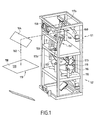
- the exposure device intended for the manufacture of printed circuit shown in FIGS. 1 to 6 has an optical system which is composed of a discharge lamp and of various optical elements.
- the lamp and a device for treatment and shaping of the light beam emitted by the lamp, as well as the panel to be exposed are fixed, and a single optical element, in this case a deflection mirror, allows the surface to be scanned of the panel to be exposed.
- FIG. 1 is an overall view of such a device comprising a panel 120 to be exposed, an optical system S 1 making it possible to process and band-form a light beam emitted by a light source 112.
- the device comprises two optical systems S 1 and S 2 making it possible to process and band-form two light beams emitted respectively by two light sources 112 and 112 'which are arranged side by side to expose the panel on these two faces.
- two similar optical systems S 1 and S 2 are then controlled simultaneously or independently depending on the device chosen.
- the light sources 112 and 112 ′ are arc lamps, for example of the Xenon Mercury type, it is necessary to orient them upwards to ensure their operation.
- the two lamps 112 and 112 ' are oriented in the same direction.
- the processing and shaping system S 1 respectively S 2 , is specific to each lamp 112, respectively 112 ', and is arranged on either side of the lamps 112 and 112' symmetrically.
- the exposure device includes a plurality of deflection mirrors, which do not process the light beam, but make it possible to form elbows in the device and in particular in the processing and shaping system. S 1 .
- mirrors are preferably flat return mirrors simple. They have no action in the treatment of the beam or in its shaping. However, it is preferable that they be treated to be dichroic, whereby they serve as a heat filter by separating the light beam between infrared and ultraviolet. Indeed, such surface treatment allows about 97% of the radiation to be reflected ultraviolet, while passing around 70% of the radiation infrared. Infrared is not useful for sunstroke, but entraining heating the plate (not shown) and surrounding elements, in especially optics, we understand that it is advantageous to separate it at earlier of the light beam and in particular before it crosses the processing and shaping system.
- FIG. 2 schematically shows such an optical system which comprises the short-arc discharge lamp 112, for example with a power of 5 kW or 8 kW, placed at the first focus 122 'of an elliptical reflector 116.
- a 5 kW lamp 112, having an arc of 3 ⁇ 3 ⁇ 7 mm 3, will be used .
- Z II Z II ' be the axis along which the different optical elements are placed, corresponding to the axis of revolution of the reflector 116 formed by a portion of ellipsoid and passing through the two focal points 122' and 124 'of said reflector 116.
- the axis Z II Z II ' is substantially vertical and corresponds to the axis of propagation of the light beam leaving the lamp 112 and the reflector 116.
- Two axes X II X II ' and Y II Y II ' are substantially perpendicular to the 'axis Z II Z II ' so as to define an orthogonal coordinate system.
- first deflection mirror 117 1 which is preferably cooled by a cooling system by blowing cold air 119.
- This first deflection mirror 117 1 is placed at 45 ° above the lamp 112 and returns the light beam I to a second deflection mirror 117 2 (see FIGS. 1 and 2).
- This second deflection mirror 117 2 is preferably oriented upwards at 45 °, so that the light beam I is reflected towards the input of the processing and shaping system, which begins with an integrator-collimator assembly 151.
- This integrator-collimator assembly 151 shown in detail in FIG. 3, comprises an assembly of different diopters allowing on the one hand, to average the illumination and to distribute the light intensity to make it homogeneous and on the other hand, to collimate it.
- the axis of the integrator-collimator assembly 151 coincides with the axis Z II Z II 'and comprises at its input 151A a first processing optic, in this case an integrating lens 150, and at its output 151B, a second processing optic, in this case a collimating lens 156.
- a first processing optic in this case an integrating lens 150
- a second processing optic in this case a collimating lens 156.
- Each of these lenses 150, respectively 156 is arranged in a support 152, respectively 154.
- the two supports 152 and 154 which are preferably covers, are placed substantially perpendicular to the axis Z II Z II ', so as to eliminate the radiation having an incidence too far from the mean direction of propagation at the outlet of the reflector 116 and so that the optical axis of the integrator-collimator assembly 151 is coincident with the axis Z II Z II 'to obtain good variation of the beam on the surface to be exposed.
- the integrating lens 150 is a convex cylindrical lens, of curvature oriented towards the collimating lens 156 and of radius of R150 curvature between 30 mm and 40 mm, preferably substantially equal to 35 mm.
- the integrating lens 150 is placed in the second focal point 124 ′ of the reflector 116.
- the light rays I are in the form of a cone of revolution whose height is substantially on the axis Z II Z II '.
- the light beam I is neither homogeneous nor collimated, at exit, the light beam II is homogeneous with a deviation of less than ⁇ 10%.
- the light beam II is also very slightly collimated by the support 152.
- This light beam II follows its path towards the collimating lens 156, which in this case is a spherical lens of curvature oriented towards the exit of the integrator-collimator assembly 151 and whose radius of curvature R 156 is between 150 mm and 200 mm, preferably substantially equal to 170 mm.
- the collimating lens 156 which in this case is a spherical lens of curvature oriented towards the exit of the integrator-collimator assembly 151 and whose radius of curvature R 156 is between 150 mm and 200 mm, preferably substantially equal to 170 mm.
- the spherical lens 156 is moved away from the spherical lens 152 so that the latter is at the focus object 156 'of the lens spherical 156.
- the light beam III is collimated with an average angle of incidence of the order of 1 °.
- the two focal points 124 'and 156' are combined and the lens spherical 156A and the reflector 116 are arranged on either side of the cylindrical lens 152. Consequently, at the outlet of the assembly integrator-collimator 151, the light beam III is homogeneous with a difference of less than ⁇ 10% and collimated.
- the focal points of the lenses 150 and 154 of the integrator-collimator assembly 151 are arranged on the same axis as that of the second focal point 124 'of the lamp 112, that is to say along the axis Z II Z' II , so that the light beam has the smallest possible declination allowing it to expose the surface of the panel to be exposed substantially perpendicularly.
- the light beam III is homogeneous with a deviation of less than ⁇ 10% and has an average angle of incidence of the order of 1 °.
- a third deflection mirror 117 3 is arranged at the outlet of the integrator-collimator assembly 151 to form the last bend in the light path III.
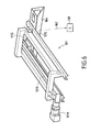
- the shaping means include shaping optics placed immediately after this third deflecting mirror 117 3 , make it possible to successively de-collimate by causing the light beam to diverge, then re-collimating the light flux III again to obtain a light strip 162.
- a first shaping optic in this case a divergent mirror 158
- a second shaping optic form in this case a converging mirror 160
- the two mirrors 158 and 160 are facing each other, preferably inclined as much as possible towards the horizontal plane (X II X ' II , Y II Y' II ) to avoid optical aberration.
- the two mirrors 158 and 160 are spaced less than 45 ° from the axis Y II Y ' II .
- the divergent mirror 158 is a convex mirror of curvature oriented towards the converging mirror 160 and whose radius of curvature R 158 is preferably between 150 mm and 200 mm.
- the converging mirror 160 it is a concave mirror with a curvature oriented in the same direction as that of the divergent mirror 158 and with a radius of curvature R 160 , preferably between 1,200 mm and 1,500 mm.
- the two mirrors 158 and 160 make it possible to obtain a light strip 162 (shown in FIG. 2) of length L 162 (shown in FIG. 4).
- the length L 162 is a function of the radius of curvature R 158 of the divergent mirror 158 and the spacing d between the two divergent mirrors 158 and converge 160.
- the width or height H 162 of the light strip 162 for its part depends on the geometric characteristics of the cover 154 and in particular of those of the spherical lens 156.
- the radius of curvature of the mirror 160 can have a small effect on the length L 162 of the light strip. For industrial reasons, this radius of curvature remains constant.
- a fourth deflection mirror 164 is placed opposite the converging mirror 160, so as to return the light strip towards the surface 118 of the panel to be exposed 120 which is placed in the horizontal plane (X II X ' II , Y II Y' II ).
- this fourth deflection mirror 164 is intended to return all or part of this length L 162 .
- the length L 126 of a light strip 126 is obtained which arrives on the surface to be exposed 118 of the printed circuit panel 120 held in a frame (not shown).
- this fourth deflection mirror 164 is the only optical element which is mobile in the device. It is understood that the surface 118 of the panel can be arranged differently.
- the scanning is carried out according to the width of the surface to be exposed, that is to say according to the axis Y II Y II '.
- the scanning is always carried out transversely to the longitudinal direction of the light strip, this scanning direction preferably being parallel to the width or at least the length of the surface to be exposed.
- the fourth deflection mirror 164 is at 45 ° relative to the axis Y II Y ′ II , so as to return the light strip to the surface 118 to be exposed in the plane defined by the axes X II X II 'and Y II Y II '.
- the width of the mirror 164 will be at least equal to the width I 118 of the surface 118 to be exposed. To expose a different surface, it suffices to change the mirror 164 or to vary the parameters of the shaping means.
- the mirror 164 must be adjusted angularly with respect to the vertical and horizontal planes by means not shown in such a way that during its movement, it remains parallel to the panel.
- the speed of movement of the mirror 164 conditions the quality and the duration of sunshine.
- the distance between the two elements increases with during scanning. It would therefore be desirable to adapt the speed of scanning, to obtain a higher quality illumination homogeneity of the entire surface to be exposed throughout the exposure.
- the homogeneity conditions set out above can be satisfied.
- a photometric sensor 138 (shown in Figure 6) sensitive to ultraviolet UV radiation is placed in the luminous flux in place of the panel to be exposed and connected to the automaton of the insolation device (not shown).
- the value of the measured flux power is sent to the controller, which calculates the speed displacement as a function of this luminous power of the flux and parameters of the surface 118 to be exposed, in particular according to the sensitivity of the material, parameters that the operator will have indicated.
- a laser is advantageously placed at the location of the panel to be exposed emitting a visible light beam towards one of the light sources 112 or 112 ′ (FIG. 1) for mechanically adjusting, by means of displacement not shown, the position of each lamp and therefore of each reflector to ensure the correct positioning of the optical axis of each integrator-collimator assembly of each of the systems S 1 and S 2 on the axis Z II Z ' II .
- This calibration is only done during the assembly of the device.
- these displacement means 121 cooperating with the device for example comprise a variable speed motor 121A which drives a belt with two pulleys 121B and a support 121D movable relative to the rails 121C on which the mirror 164 is fixed. All types of known means of travel can be used to move the mirror 164.
- the speed of the displacement means is variable for compensate for the loss of light power due to the progressive spacing of the mirror 164 with respect to the lamp 112.
- a starting speed V Max determined when the mirror 164 is closest to the lamp 112 (at the start of the sunshine), will regularly decrease until reaching a minimum value V MIN , when the scanning of the entire surface 118 is finished.
- the adaptation means comprise a servo loop programmed in the automaton which makes it possible to calculate and adapt the speed of the mirror 164.
- a significant downtime is essential (several ten minutes) before being able to relight the lamps, especially to ensure that they have sufficiently cooled.
- the downtime also includes the necessary time to stabilize the lamps so that the light is emitted homogeneously.
- the life of a lamp is inversely proportional to the number of times the lamp is on and off.
- the device comprises a flap (not shown) which can be arranged in the vicinity of the cylindrical lens 152 for mask the radiation without having to turn off the lamp 112.
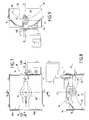
- the exposure device intended for the manufacture of printed circuit shown in FIGS. 7 to 12 comprises an optical system which is composed of a set of light boxes each comprising a specially shaped reflector and a discharge lamp provides a collimated light strip and homogeneous.
- the entire optical system, in particular the light source, is mobile and the panel is fixed.
- Figure 7 shows such a light box 10 which comprises a medium arc discharge lamp 12, preferably of length 20 mm and power 500 W.
- the lamp 12 is placed in a housing 14 in which a reflector 16 has been placed.
- axis X I X I ' as the horizontal axis corresponding to the direction of the width of the surface 18 of the panel to be exposed 20 disposed substantially vertically (shown in FIG. 10 without the plate or the holding frame ), it suffices to move the light box along the axis Y I Y I ', substantially transverse to the axis X I X I ' to scan the entire surface 18.
- the reflector 16 has a surface formed by a first parabola 24 in the vertical plane defined by the axes Y I Y I 'and Z I Z I ' (represented in FIG. 9) and a second parabola 22 in the horizontal plane defined by the axes X I X I 'and Z I Z I ' (shown in Figure 8), having respectively a first focus 24 'and a second focus (not shown) on the axis Z I Z I '.
- the lamp 12 is placed on the first focus 24 '.
- the light rays are therefore preferably sent along the axis Z I Z I '.
- the correct positioning of the lamp 12 in such a reflector 16 conditions the collimation and the declination of the light beam.
- the reflector 16 is produced in two parts 16A and 16B symmetrical with respect to the plane horizontal.
- the reflector has a central opening 16C which is made in the two parts 16A and 16B of the reflector 16.
- the two parts 16A and 16B are not contiguous, but separated from each other by said opening 16C.
- This opening 16C has a defined adequate shape according to the geometry of the lamp 12.
- a length L 26 equal to the width I 18 of the surface 18, preferably 635 mm and a height H 26 between 100 mm and 150 mm, preferably 130 mm, it is preferable to place five light boxes 10 as defined above.
- the panel 20 is arranged substantially at vertically, just align the five light boxes 10 along the axis horizontal to form the light strip 26.
- the light boxes 10 are separated from each other by a nominal distance preferential of 145 mm, it is this distance between the light boxes which conditions the homogeneity of the light beam.
- a setting of the position of each light box 10 compensates for errors for making the light box 10.
- this adjustment can have an amplitude of ⁇ 5 mm around the nominal position.
- the light strip 26 has an average angle of incidence of the order of 11 ° and a deviation in the uniformity of the illumination of ⁇ 10% from the average value which is around 120 mW. cm -2 . In fact, half of the flux arrives on the surface 18 with an angle of incidence less than 11 °.
- the set of light boxes 10 is arranged on a support 28 movable in translation, in the horizontal plane, to allow adjustment the distance between all of the light boxes 10 and the panel 20 to to be exposed, depending on the position of the surface to be exposed which depends on the position of the retaining frame (not shown).
- This distance from the center from the lamp to the panel is preferably 180 mm. This distance determines the quality of the homogeneity of the light strip.
- the support 28 is, for example, arranged on a rail comprising the part female 30 of a dovetail which slides on the fixed male part 32 on a drive support 34 movable in translation in the direction vertical, corresponding to the scanning direction.
- the means of displacement include a drive system training support 34.
- the device comprises a flap 36 fixed on the support 28 capable of rotate in front of the lamps 12.
- the closed position (during a change of panel 20 for example), as shown in the figure 10, the flow of the light strip 26 is interrupted, while the lamps 12 can stay on.
- the flap 36 is shown in position open, during the exposure of a panel 20 (not shown) on the Figure 11.
- the use of such a shutter 36 thus makes it possible to avoid switching off the lamps 12 between each change of panels 20 to be exposed and this made to reduce the manufacturing time of the printed circuit.
- the speed of movement of this drive support 34 determines the quality and duration of the sunshine. To determine this speed, the operator introduces the characteristics of the surface to be exposed, particularly the sensitivity of the material, in a computer of the automaton of the insolation device (not shown). Travel speed is determined at each change of surface type 18 of the panels 20 to be exposed.
- the automaton calculates the light power of the light strip 26 from the light output of each lamp 12.
- Calibration means 38 comprising a calibration cell 40 and a dichroic 42 arranged on a mobile support 44.
- the means of calibration are connected to the automation of the insolation device (no shown), so as to provide the light output of the lamp 12 that we want to calibrate.
- the automaton adjusts the power intensity of the lamp 12, until obtaining the desired power measured by the calibration means 38.
- the calibration of the lamps 12 is made during the start-up of the device for controlling the stabilization of the lamps 12 and as soon as a lamp 12 or surface type change is carried out insolated.
- the calibration means 38 can also be used for checking regular lamps 12 throughout their use. Indeed, during aging of a lamp, with electric power supply constant, it provides less and less light power. Thus, a servo of the regular adaptation of the power the lamp as a function of the loss of light power measured, allows to have a light strip 26 of substantially intensity constant over time.
- the calibration means 38 are mobile, using a motor 46 for example, so that they can be placed in front of each lamp 12 of all the light boxes 10.
- Means of adaptation include the servo of the means of displacement of the support 34.
- Means of adaptation can, for example, include a motor controlled by a control loop connected to the device controller. The loop being directly determined by the PLC, depending on the desired light output and the type of area.
- the device has tangential fans 19 placed below the boxes to light 10 which blows cold air towards deflectors 19 'which allow to generate a band of air which propagates towards the surface to expose 18 and the image, in particular towards the area of the image exposed by the light strip 26.
Landscapes
- Physics & Mathematics (AREA)
- General Physics & Mathematics (AREA)
- Exposure And Positioning Against Photoresist Photosensitive Materials (AREA)
Abstract
Description
- des moyens pour maintenir au moins un cliché et ledit panneau sur un cadre,
- un système optique comportant une source lumineuse émettant un faisceau lumineux, des moyens de traitement dudit faisceau lumineux pour générer un faisceau lumineux homogène et collimaté dont l'angle d'incidence moyen par rapport à la surface à insoler est inférieur à 2° et dont l'homogénéité de l'éclairement présente un écart inférieur à ± 10% par rapport à la valeur moyenne, et des moyens de mise en forme permettant de transformer ledit faisceau lumineux homogène et collimaté en une bande lumineuse homogène et collimatée sur la surface du panneau à insoler comportant ledit cliché, ladite bande lumineuse homogène et collimatée étant de longueur au moins égale à la longueur d'un des côtés de ladite surface à insoler, lesdits moyens de traitement du faisceau lumineux comportant un réflecteur et un ensemble intégrateur-collimateur,
- des moyens de déplacement pour générer un mouvement relatif entre ladite bande lumineuse et ladite face à insoler dans la direction sensiblement transversale à la direction longitudinale de ladite bande lumineuse et,
- des moyens d'adaptation de la vitesse de déplacement relative entre ladite bande lumineuse et ladite face à insoler en fonction de l'éclairement de la bande lumineuse et de la sensibilité de la surface à insoler.
- des moyens pour maintenir au moins un cliché et ledit panneau sur un cadre,
- un système optique comportant au moins une boíte à lumière comportant une source lumineuse et un réflecteur comportant au moins une première parabole ayant un premier foyer et une deuxième parabole ayant un deuxième foyer, lesdits premier et deuxième foyers étant situés sur l'axe correspondant à ladite direction de balayage de ladite face à insoler et en ce que la source lumineuse est placée audit premier foyer pour générer une bande lumineuse sur la surface du panneau à insoler comportant ledit cliché dont l'angle d'incidence moyen est inférieur à 15° et dont l'homogénéité de l'éclairement présente un écart inférieur à ± 10% par rapport à la valeur moyenne, ladite bande lumineuse collimatée étant de longueur au moins égale à la longueur d'un des côtés de ladite surface à insoler,
- des moyens de déplacement pour générer un mouvement relatif entre ladite bande lumineuse et ladite face à insoler dans la direction sensiblement transversale à la direction longitudinale de ladite bande lumineuse et,
- des moyens d'adaptation de la vitesse de déplacement relative entre ladite bande lumineuse et ladite face à insoler en fonction de l'éclairement de la bande lumineuse et de la sensibilité de la surface à insoler.
- la figure 1 est une vue en perspective du dispositif d'insolation selon le premier aspect de l'invention,
- la figure 2 est une vue schématique du chemin parcouru par un rayon lumineux dans le dispositif de la figure 1,
- la figure 3 est une vue en perspective de l'ensemble intégrateur-collimateur,
- la figure 4 est une représentation schématique de la figure 1 vue de dessus,
- la figure 5 est une représentation schématique identique à la figure 4 en vue de côté,
- la figure 6 est une vue en perspective montrant les moyens de déplacement,
- la figure 7 est une vue d'une boíte à lumière selon le deuxième aspect de l'invention,
- la figure 8 est une coupe de la boite à lumière de la figure 7 selon VIII-VIII,
- la figure 9 est une coupe de la boite à lumière de la figure 7 selon IX-IX,
- la figure 10 est une vue en perspective d'un ensemble de cinq boites à lumière vue de derrière,
- la figure 11 est une vue en perspective de l'ensemble des cinq boites à lumière de la figure 10, vue de devant, et
- la figure 12 est une vue en perspective des moyens de calibration.
Claims (30)
- Dispositif pour insoler au moins une face (118) d'un panneau (120), en particulier pour panneau de circuit imprimé, comprenant :des moyens pour maintenir au moins un cliché et ledit panneau (120) sur un cadre,un système optique comportant une source lumineuse (112) émettant un faisceau lumineux (I), des moyens de traitement dudit faisceau lumineux (I) pour générer un faisceau lumineux homogène et collimaté (III) dont l'angle d'incidence moyen par rapport à la surface à insoler (118) est inférieur à 2° et dont l'homogénéité de l'éclairement présente un écart inférieur à ± 10% par rapport à la valeur moyenne, et des moyens de mise en forme (158, 160) permettant de transformer ledit faisceau lumineux homogène et collimaté (III) en une bande lumineuse (126) homogène et collimatée sur la surface (118) du panneau (120) à insoler comportant ledit cliché, ladite bande lumineuse (126) homogène et collimatée étant de longueur (L126) au moins égale à la longueur (I118) d'un des côtés de ladite surface (118) à insoler, lesdits moyens de traitement du faisceau lumineux (I) comportant un réflecteur (116) et un ensemble intégrateur-collimateur (151),des moyens de déplacement (121) pour générer un mouvement relatif entre ladite bande lumineuse (126) et ladite face (118) à insoler dans la direction (ZIZI'; ZIIZII') sensiblement transversale à la direction longitudinale (XIXI'; XIIXII') de ladite bande lumineuse (126) et,des moyens d'adaptation de la vitesse de déplacement relative entre ladite bande lumineuse (126) et ladite face (118) à insoler en fonction de l'éclairement de la bande lumineuse (126) et de la sensibilité de la surface à insoler (118).
- Dispositif selon la revendication précédente, caractérisé en ce que ledit réflecteur (116) comporte une portion d'un ellipsoïde de révolution et en ce que ledit ellipsoïde de révolution présente un premier foyer (122') et un deuxième foyer (124').
- Dispositif selon l'une quelconque des revendications précédentes, caractérisé en ce que ledit ensemble intégrateur-collimateur (151) comporteune première optique de traitement (150) destinée à distribuer la lumière de manière sensiblement homogène,une deuxième optique de traitement (156) présentant un foyer objet (156'), ladite deuxième optique de traitement (156) étant disposée après ladite première optique de traitement (150) et étant destinée à collimater la lumière.
- Dispositif selon les revendications 2 et 3, caractérisé en ce que ladite première optique de traitement (150) est disposée au deuxième foyer (124') dudit réflecteur (116), de sorte que ladite première optique de traitement (150) permette de traiter ledit faisceau lumineux (I) y entrant en un faisceau lumineux sortant homogène (II).
- Dispositif selon la revendication précédente, caractérisé en ce que ladite première optique de traitement (150) est disposée au foyer objet (156') de ladite seconde optique de traitement (156), de sorte que cette dernière (156) permette de traiter ledit faisceau lumineux homogène (II) y entrant en un faisceau homogène et collimaté (III).
- Dispositif selon l'une quelconque des revendications 3 à 5, caractérisé en ce que ladite première optique de traitement (150) est une lentille intégratrice cylindrique (150) de rayon de courbure (R150) compris entre 30 mm et 40 mm.
- Dispositif selon l'une quelconque des revendications 3 à 6, caractérisé en ce que ladite deuxième optique de traitement (156) est une lentille collimatrice sphérique (156) de rayon de courbure (R156) compris entre 150 mm et 200 mm.
- Dispositif selon la revendication précédente, caractérisé en ce que ledit ensemble intégrateur-collimateur (151) comporte en outre :un premier cache (152) placé au voisinage de ladite première optique (150),un deuxième cache (154) placé au voisinage de ladite deuxième optique (156).
- Dispositif selon l'une quelconque des revendications précédentes, caractérisé en ce que ladite source lumineuse (112) est disposée au premier foyer (122') dudit réflecteur (116).
- Dispositif selon l'une quelconque des revendications précédentes, caractérisé en ce qu'il comporte en outre au moins un miroir dichroïque (1171, 1172, 1173).
- Dispositif selon l'une quelconque des revendications précédentes, caractérisé en ce que lesdits moyens de mise en forme (158, 160) comportent une première optique de mise en forme (158) et une deuxième optique de mise en forme (160) qui sont successivement disposés à la sortie dudit ensemble intégrateur-collimateur (151).
- Dispositif selon la revendication précédente, caractérisé en ce que ladite première optique de forme est un miroir divergent (158) qui est convexe et de courbure (R158) et en ce que ladite deuxième optique de mise en forme est un miroir convergent (160) qui est concave et de courbure (R160).
- Dispositif selon la revendication précédente, caractérisé en ce que lesdits miroirs divergent (158) et convergent (160) sont écartés d'une distance d'écartement (d) et en ce que la longueur (L126) de ladite bande lumineuse (126) homogène et collimatée est fonction de ladite distance d'écartement (d) et des rayons de courbure (R158, R160) desdits miroirs convergent (158) et divergent (160).
- Dispositif selon l'une quelconque des revendications précédentes, caractérisé en ce que lesdits moyens de déplacement comportent un miroir de renvoi (164) plan et mobile dans le plan défini par les axes (XIIXII', ZIIZII') de la face (118) du panneau (120) à insoler.
- Dispositif pour insoler au moins une face (18) d'un panneau (20), en particulier pour panneau de circuit imprimé, comprenant :des moyens pour maintenir au moins un cliché et ledit panneau (20) sur un cadre,un système optique comportant au moins une boíte à lumière (10) comportant une source lumineuse (12) et un réflecteur (16) comportant au moins une première parabole (24) ayant un premier foyer (24') et une deuxième parabole (22) ayant un deuxième foyer, lesdits premier (22') et deuxième foyers étant situés sur l'axe (ZIZI'; ZIIZII') correspondant à ladite direction de balayage de ladite face (18) à insoler et en ce que la source lumineuse (12) est placée audit premier foyer (24') pour générer une bande lumineuse (26) sur la surface (18) du panneau (20) à insoler comportant ledit cliché dont l'angle d'incidence moyen est inférieur à 15° et dont l'homogénéité de l'éclairement présente un écart inférieur à ± 10% par rapport à la valeur moyenne, ladite bande lumineuse (26) collimatée étant de longueur (L26) au moins égale à la largeur (I18) de ladite surface (18) à insoler,des moyens de déplacement pour générer un mouvement relatif entre ladite bande lumineuse (26) et ladite face (18) à insoler dans la direction (ZIZI'; ZIIZII') de la longueur de ladite face (18) à insoler, direction qui est sensiblement transversale à la direction longitudinale (XIXI'; XIIXII') de ladite bande lumineuse (26) et,des moyens d'adaptation de la vitesse de déplacement relative entre ladite bande lumineuse (26) et ladite face (18) à insoler en fonction de l'éclairement de la bande lumineuse (26) et de la sensibilité de la surface à insoler (18).
- Dispositif selon la revendication précédente, caractérisé en ce que ladite première parabole (24) se situe dans un premier plan défini par les axes (YIYI', ZIZI') comportant ladite direction de balayage (ZIZI' ; ZIIZII') et ladite deuxième parabole (22) se situe dans un deuxième plan défini par les axes (XIXI', ZIZI') comportant ladite direction de balayage (ZIZI'; ZIIZII') et sensiblement transversal au dit premier plan.
- Dispositif selon l'une quelconque des revendications 15 et 16, caractérisé en ce que ledit réflecteur (16) comporte en outre deux parties symétriques (16A, 16B).
- Dispositif selon l'une quelconque des revendications 15 à 17, caractérisé en ce que ledit réflecteur (16) comporte en outre une ouverture centrale (16C) destinée à faciliter le changement de lampe (12).
- Dispositif selon l'une quelconque des revendications 15 à 18, caractérisé en ce que ledit système optique comprend cinq boítes à lumière (10) alignées selon la direction (XIXI') sensiblement transversale à ladite direction de balayage (ZIZI').
- Dispositif selon la revendication précédente, caractérisé en ce que chacune desdites boítes à lumière (10) est déplaçable l'une par rapport à l'autre selon la direction longitudinale de la bande lumineuse (XIXI').
- Dispositif selon l'une quelconque des revendications précédentes, caractérisé en ce que ladite bande lumineuse (26 ; 126) homogène et collimatée forme un quadrilatère de hauteur (H26; H126) comprise entre 100 mm et 150 mm et de longueur (L26; L126) au moins égale à la largeur (I18 ; I118) de ladite surface (18 ; 118) à insoler.
- Dispositif selon l'une quelconque des revendications précédentes, caractérisé en ce que ladite source lumineuse (12 ; 112) comprend une lampe à décharge électrique (12 ; 112).
- Dispositif selon l'une quelconque des revendications 1 à 21, caractérisé en ce que ladite bande lumineuse (26 ; 126) présente un angle d'incidence moyen inférieur ou égal à 15°.
- Dispositif selon l'une quelconque des revendications 1 à 21, caractérisé en ce que ladite bande lumineuse (26 ; 126) présente un angle d'incidence moyen inférieur ou égal à 2°.
- Dispositif selon l'une quelconque des revendications 1 à 23, caractérisé en ce que ladite source lumineuse (12 ; 112) comporte une lampe à décharge électrique à arc moyen (12).
- Dispositif selon l'une quelconque des revendications 1 à 23, caractérisé en ce que ladite source lumineuse (12 ; 112) comporte une lampe à décharge électrique à arc court (112).
- Dispositif selon l'une quelconque des revendications précédentes, caractérisé en ce qu'il comporte en outre des moyens de calibration pour calibrer (38, 40) chaque source lumineuse (12) indépendamment l'une de l'autre.
- Dispositif selon la revendication 26, caractérisé en ce que lesdits moyens de calibration (38) sont déplaçables devant chaque source lumineuse (12).
- Dispositif selon l'une quelconque des revendications précédentes, caractérisé en ce qu'il comporte en outre un capteur photométrique (138) destiné à mesurer la puissance du flux lumineux.
- Dispositif selon l'une quelconque des revendications précédentes, caractérisé en ce que les moyens d'adaptation permettent en outre de faire varier la vitesse de déplacement relative entre ladite bande lumineuse (26 ; 126) et ladite face (18 ; 118) à insoler au cours de l'insolation.
Applications Claiming Priority (2)
| Application Number | Priority Date | Filing Date | Title |
|---|---|---|---|
| FR0104186 | 2001-03-28 | ||
| FR0104186A FR2822967B1 (fr) | 2001-03-28 | 2001-03-28 | Dispositif pour insoler une face d'un panneau de circuit imprime |
Publications (2)
| Publication Number | Publication Date |
|---|---|
| EP1245998A2 true EP1245998A2 (fr) | 2002-10-02 |
| EP1245998A3 EP1245998A3 (fr) | 2007-06-13 |
Family
ID=8861641
Family Applications (1)
| Application Number | Title | Priority Date | Filing Date |
|---|---|---|---|
| EP02290697A Withdrawn EP1245998A3 (fr) | 2001-03-28 | 2002-03-20 | Dispositif pour insoler une face d'un panneau de circuit imprimé |
Country Status (8)
| Country | Link |
|---|---|
| US (1) | US6646279B2 (fr) |
| EP (1) | EP1245998A3 (fr) |
| JP (1) | JP2002333720A (fr) |
| KR (1) | KR20020077212A (fr) |
| CN (1) | CN1266546C (fr) |
| CA (1) | CA2379101A1 (fr) |
| FR (1) | FR2822967B1 (fr) |
| TW (1) | TW594384B (fr) |
Families Citing this family (7)
| Publication number | Priority date | Publication date | Assignee | Title |
|---|---|---|---|---|
| US8694510B2 (en) | 2003-09-04 | 2014-04-08 | Oracle International Corporation | Indexing XML documents efficiently |
| US7930277B2 (en) | 2004-04-21 | 2011-04-19 | Oracle International Corporation | Cost-based optimizer for an XML data repository within a database |
| WO2006064363A1 (fr) * | 2004-12-14 | 2006-06-22 | Radove Gmbh | Processus et appareil de production de rayons uv de collimation pour transfert photolithographique |
| US8073841B2 (en) | 2005-10-07 | 2011-12-06 | Oracle International Corporation | Optimizing correlated XML extracts |
| KR100880858B1 (ko) * | 2007-08-09 | 2009-01-30 | 한기수 | 피씨비 양면 동시 노광기 광원 구조 |
| CN108803237A (zh) * | 2018-06-08 | 2018-11-13 | 东莞市银泰丰光学科技有限公司 | 一种玻璃导光板的加工装置及其加工方法 |
| CN115309002A (zh) * | 2022-07-04 | 2022-11-08 | 湖北源合达科技有限公司 | 一种平行曝光机 |
Citations (1)
| Publication number | Priority date | Publication date | Assignee | Title |
|---|---|---|---|---|
| US4965621A (en) | 1989-11-17 | 1990-10-23 | Eastman Kodak Company | Compact light collimator for a scanning contact printer |
Family Cites Families (9)
| Publication number | Priority date | Publication date | Assignee | Title |
|---|---|---|---|---|
| DE2603879A1 (de) * | 1976-02-02 | 1977-08-04 | Siemens Ag | Belichtungsanordnung |
| US4111538A (en) * | 1976-02-25 | 1978-09-05 | Xerox Corporation | Projection system of high efficiency |
| US4258395A (en) * | 1979-09-12 | 1981-03-24 | The Mead Corporation | Document scanning system |
| DE2944312A1 (de) * | 1979-11-02 | 1981-05-14 | Hans 6250 Limburg Haus | Vorrichtung zum belichten von, auf eine ebene auflageflaeche geschichtetem kopier- und belichtungsgut mittels gerichteten lichts |
| CH665492A5 (de) * | 1984-11-13 | 1988-05-13 | Mettler Instrumente Ag | Verfahren zum gleichmaessigen belichten einer kopierflaeche und einrichtung zur durchfuehrung des verfahrens. |
| US4987445A (en) * | 1989-10-13 | 1991-01-22 | Burgess Industries Inc. | Scanning light contact duplicating apparatus |
| DE9003438U1 (de) * | 1990-03-23 | 1990-05-31 | Croon Reprografische Industrie, Mijdrecht | Belichtungskonstruktion zum Belichten großer reckteckiger Flächen |
| US5416683A (en) * | 1994-05-25 | 1995-05-16 | Kenall Manufacturing Co. | Drop dish lighting fixture with rectangular beam pattern |
| EP0730194A1 (fr) * | 1995-03-02 | 1996-09-04 | Agfa-Gevaert N.V. | Appareil d'exposition photographique |
-
2001
- 2001-03-28 FR FR0104186A patent/FR2822967B1/fr not_active Expired - Fee Related
-
2002
- 2002-03-20 EP EP02290697A patent/EP1245998A3/fr not_active Withdrawn
- 2002-03-26 TW TW091105916A patent/TW594384B/zh not_active IP Right Cessation
- 2002-03-27 CA CA002379101A patent/CA2379101A1/fr not_active Abandoned
- 2002-03-28 JP JP2002092184A patent/JP2002333720A/ja active Pending
- 2002-03-28 US US10/109,225 patent/US6646279B2/en not_active Expired - Fee Related
- 2002-03-28 KR KR1020020017145A patent/KR20020077212A/ko not_active Abandoned
- 2002-03-28 CN CNB021217971A patent/CN1266546C/zh not_active Expired - Fee Related
Patent Citations (1)
| Publication number | Priority date | Publication date | Assignee | Title |
|---|---|---|---|---|
| US4965621A (en) | 1989-11-17 | 1990-10-23 | Eastman Kodak Company | Compact light collimator for a scanning contact printer |
Also Published As
| Publication number | Publication date |
|---|---|
| FR2822967B1 (fr) | 2003-10-03 |
| EP1245998A3 (fr) | 2007-06-13 |
| CA2379101A1 (fr) | 2002-09-28 |
| FR2822967A1 (fr) | 2002-10-04 |
| JP2002333720A (ja) | 2002-11-22 |
| US20020167788A1 (en) | 2002-11-14 |
| TW594384B (en) | 2004-06-21 |
| CN1391137A (zh) | 2003-01-15 |
| CN1266546C (zh) | 2006-07-26 |
| US6646279B2 (en) | 2003-11-11 |
| KR20020077212A (ko) | 2002-10-11 |
Similar Documents
| Publication | Publication Date | Title |
|---|---|---|
| EP0299836B1 (fr) | Système optique et appareil chirurgical comportant ledit système | |
| JP5329520B2 (ja) | 低角度で入射する補正光を用いる補正光学素子 | |
| JP3640391B1 (ja) | 照明光学装置 | |
| FR2591717A1 (fr) | Dispositif de source lumineuse notamment pour machine de gestion ou de bureau | |
| EP1245998A2 (fr) | Dispositif pour insoler une face d'un panneau de circuit imprimé | |
| EP0018249A1 (fr) | Dispositif illuminateur destiné à fournir un faisceau d'éclairement divergent à partir d'une zône prédéterminée d'un plan et système de transfert de motifs comprenant un tel dispositif | |
| FR2621711A1 (fr) | Procede et dispositif pour compenser l'influence de parametres de l'environnement sur les caracteristiques de reproduction d'un systeme optique | |
| EP0000450A1 (fr) | Appareils de reproduction photographique de documents transparents, notamment du type agrandisseur photographique | |
| CN115066893B (zh) | 用于校准、安装和/或检查光电学系统的设备、方法和设备的应用 | |
| FR2831967A1 (fr) | Appareil et procede d'exposition d'un objet a de la lumiere | |
| EP3069156B1 (fr) | Dispositif et procede de test d'un module photovoltaique a concentration | |
| FR2691814A1 (fr) | Procédé et appareillage d'impression d'une image. | |
| WO2003071778A1 (fr) | Procede pour transferer une image numerique en vue de sa restitution visuelle, et dispositif pour la mise en oeuvre de ce procede | |
| FR2639723A1 (fr) | Projecteur d'image reelle lumineuse reflechie | |
| FR2831765A1 (fr) | Dispositif pour insoler une face d'un panneau | |
| FR2639857A1 (fr) | Dispositif pour le traitement d'une surface par balayage d'un faisceau laser | |
| FR2735245A1 (fr) | Tete de son optique et projecteur pour films sonores ainsi equipe | |
| EP0199650A1 (fr) | Appareil de régulation de caractéristiques d'un faisceau lumineux, notamment d'un laser de puissance | |
| EP0221606B1 (fr) | Dispositif optique de prise de vue ou de projection | |
| FR3139735A1 (fr) | Procédé et dispositif de dépôt de couche mince sur surface courbe | |
| JP5557225B2 (ja) | 単色光照射装置 | |
| FR3073839B1 (fr) | Systeme d’alignement d’un dispositif de traitement thermique et son fonctionnement | |
| FR2673009A1 (fr) | Systeme holographique de duplication d'objets plans capable d'un pouvoir de resolution tres eleve. | |
| FR2666421A1 (fr) | Projecteur a arc au xenon de forte puissance. | |
| EP1097573A1 (fr) | Dispositif d'affichage par retroprojection |
Legal Events
| Date | Code | Title | Description |
|---|---|---|---|
| PUAI | Public reference made under article 153(3) epc to a published international application that has entered the european phase |
Free format text: ORIGINAL CODE: 0009012 |
|
| AK | Designated contracting states |
Kind code of ref document: A2 Designated state(s): AT BE CH CY DE DK ES FI FR GB GR IE IT LI LU MC NL PT SE TR |
|
| AX | Request for extension of the european patent |
Free format text: AL;LT;LV;MK;RO;SI |
|
| PUAL | Search report despatched |
Free format text: ORIGINAL CODE: 0009013 |
|
| AK | Designated contracting states |
Kind code of ref document: A3 Designated state(s): AT BE CH CY DE DK ES FI FR GB GR IE IT LI LU MC NL PT SE TR |
|
| AX | Request for extension of the european patent |
Extension state: AL LT LV MK RO SI |
|
| RIC1 | Information provided on ipc code assigned before grant |
Ipc: F21V 7/08 20060101ALI20070507BHEP Ipc: F21V 7/06 20060101ALI20070507BHEP Ipc: H05K 3/00 20060101ALI20070507BHEP Ipc: G03B 27/10 20060101ALI20070507BHEP Ipc: G03F 7/20 20060101AFI20070507BHEP |
|
| 17P | Request for examination filed |
Effective date: 20071102 |
|
| AKX | Designation fees paid |
Designated state(s): AT BE CH CY DE DK ES FI FR GB GR IE IT LI LU MC NL PT SE TR |
|
| 17Q | First examination report despatched |
Effective date: 20090407 |
|
| GRAP | Despatch of communication of intention to grant a patent |
Free format text: ORIGINAL CODE: EPIDOSNIGR1 |
|
| STAA | Information on the status of an ep patent application or granted ep patent |
Free format text: STATUS: THE APPLICATION IS DEEMED TO BE WITHDRAWN |
|
| 18D | Application deemed to be withdrawn |
Effective date: 20110816 |