EP1246300A2 - Bindungselement für koaxiales Kabel und ein elektrischer Verbinder für koaxiales Kabel, beide unter Verwendung von Harz-Lötpaste, und Verfahren zur Verbindung - Google Patents
Bindungselement für koaxiales Kabel und ein elektrischer Verbinder für koaxiales Kabel, beide unter Verwendung von Harz-Lötpaste, und Verfahren zur Verbindung Download PDFInfo
- Publication number
- EP1246300A2 EP1246300A2 EP02007084A EP02007084A EP1246300A2 EP 1246300 A2 EP1246300 A2 EP 1246300A2 EP 02007084 A EP02007084 A EP 02007084A EP 02007084 A EP02007084 A EP 02007084A EP 1246300 A2 EP1246300 A2 EP 1246300A2
- Authority
- EP
- European Patent Office
- Prior art keywords
- binding member
- conductor
- coaxial cable
- lead
- electric
- Prior art date
- Legal status (The legal status is an assumption and is not a legal conclusion. Google has not performed a legal analysis and makes no representation as to the accuracy of the status listed.)
- Withdrawn
Links
Images



Classifications
-
- H—ELECTRICITY
- H01—ELECTRIC ELEMENTS
- H01R—ELECTRICALLY-CONDUCTIVE CONNECTIONS; STRUCTURAL ASSOCIATIONS OF A PLURALITY OF MUTUALLY-INSULATED ELECTRICAL CONNECTING ELEMENTS; COUPLING DEVICES; CURRENT COLLECTORS
- H01R9/00—Structural associations of a plurality of mutually-insulated electrical connecting elements, e.g. terminal strips or terminal blocks; Terminals or binding posts mounted upon a base or in a case; Bases therefor
- H01R9/03—Connectors arranged to contact a plurality of the conductors of a multiconductor cable, e.g. tapping connections
- H01R9/05—Connectors arranged to contact a plurality of the conductors of a multiconductor cable, e.g. tapping connections for coaxial cables
-
- H—ELECTRICITY
- H01—ELECTRIC ELEMENTS
- H01R—ELECTRICALLY-CONDUCTIVE CONNECTIONS; STRUCTURAL ASSOCIATIONS OF A PLURALITY OF MUTUALLY-INSULATED ELECTRICAL CONNECTING ELEMENTS; COUPLING DEVICES; CURRENT COLLECTORS
- H01R4/00—Electrically-conductive connections between two or more conductive members in direct contact, i.e. touching one another; Means for effecting or maintaining such contact; Electrically-conductive connections having two or more spaced connecting locations for conductors and using contact members penetrating insulation
- H01R4/02—Soldered or welded connections
- H01R4/023—Soldered or welded connections between cables or wires and terminals
- H01R4/024—Soldered or welded connections between cables or wires and terminals comprising preapplied solder
-
- H—ELECTRICITY
- H01—ELECTRIC ELEMENTS
- H01R—ELECTRICALLY-CONDUCTIVE CONNECTIONS; STRUCTURAL ASSOCIATIONS OF A PLURALITY OF MUTUALLY-INSULATED ELECTRICAL CONNECTING ELEMENTS; COUPLING DEVICES; CURRENT COLLECTORS
- H01R9/00—Structural associations of a plurality of mutually-insulated electrical connecting elements, e.g. terminal strips or terminal blocks; Terminals or binding posts mounted upon a base or in a case; Bases therefor
- H01R9/03—Connectors arranged to contact a plurality of the conductors of a multiconductor cable, e.g. tapping connections
- H01R9/05—Connectors arranged to contact a plurality of the conductors of a multiconductor cable, e.g. tapping connections for coaxial cables
- H01R9/0515—Connection to a rigid planar substrate, e.g. printed circuit board
-
- H—ELECTRICITY
- H01—ELECTRIC ELEMENTS
- H01R—ELECTRICALLY-CONDUCTIVE CONNECTIONS; STRUCTURAL ASSOCIATIONS OF A PLURALITY OF MUTUALLY-INSULATED ELECTRICAL CONNECTING ELEMENTS; COUPLING DEVICES; CURRENT COLLECTORS
- H01R13/00—Details of coupling devices of the kinds covered by groups H01R12/70 or H01R24/00 - H01R33/00
- H01R13/02—Contact members
- H01R13/03—Contact members characterised by the material, e.g. plating, or coating materials
-
- H—ELECTRICITY
- H05—ELECTRIC TECHNIQUES NOT OTHERWISE PROVIDED FOR
- H05K—PRINTED CIRCUITS; CASINGS OR CONSTRUCTIONAL DETAILS OF ELECTRIC APPARATUS; MANUFACTURE OF ASSEMBLAGES OF ELECTRICAL COMPONENTS
- H05K3/00—Apparatus or processes for manufacturing printed circuits
- H05K3/30—Assembling printed circuits with electric components, e.g. with resistors
- H05K3/32—Assembling printed circuits with electric components, e.g. with resistors electrically connecting electric components or wires to printed circuits
- H05K3/321—Assembling printed circuits with electric components, e.g. with resistors electrically connecting electric components or wires to printed circuits by conductive adhesives
-
- Y—GENERAL TAGGING OF NEW TECHNOLOGICAL DEVELOPMENTS; GENERAL TAGGING OF CROSS-SECTIONAL TECHNOLOGIES SPANNING OVER SEVERAL SECTIONS OF THE IPC; TECHNICAL SUBJECTS COVERED BY FORMER USPC CROSS-REFERENCE ART COLLECTIONS [XRACs] AND DIGESTS
- Y10—TECHNICAL SUBJECTS COVERED BY FORMER USPC
- Y10S—TECHNICAL SUBJECTS COVERED BY FORMER USPC CROSS-REFERENCE ART COLLECTIONS [XRACs] AND DIGESTS
- Y10S428/00—Stock material or miscellaneous articles
- Y10S428/901—Printed circuit
-
- Y—GENERAL TAGGING OF NEW TECHNOLOGICAL DEVELOPMENTS; GENERAL TAGGING OF CROSS-SECTIONAL TECHNOLOGIES SPANNING OVER SEVERAL SECTIONS OF THE IPC; TECHNICAL SUBJECTS COVERED BY FORMER USPC CROSS-REFERENCE ART COLLECTIONS [XRACs] AND DIGESTS
- Y10—TECHNICAL SUBJECTS COVERED BY FORMER USPC
- Y10T—TECHNICAL SUBJECTS COVERED BY FORMER US CLASSIFICATION
- Y10T428/00—Stock material or miscellaneous articles
- Y10T428/13—Hollow or container type article [e.g., tube, vase, etc.]
- Y10T428/1352—Polymer or resin containing [i.e., natural or synthetic]
- Y10T428/139—Open-ended, self-supporting conduit, cylinder, or tube-type article
-
- Y—GENERAL TAGGING OF NEW TECHNOLOGICAL DEVELOPMENTS; GENERAL TAGGING OF CROSS-SECTIONAL TECHNOLOGIES SPANNING OVER SEVERAL SECTIONS OF THE IPC; TECHNICAL SUBJECTS COVERED BY FORMER USPC CROSS-REFERENCE ART COLLECTIONS [XRACs] AND DIGESTS
- Y10—TECHNICAL SUBJECTS COVERED BY FORMER USPC
- Y10T—TECHNICAL SUBJECTS COVERED BY FORMER US CLASSIFICATION
- Y10T428/00—Stock material or miscellaneous articles
- Y10T428/28—Web or sheet containing structurally defined element or component and having an adhesive outermost layer
- Y10T428/2804—Next to metal
-
- Y—GENERAL TAGGING OF NEW TECHNOLOGICAL DEVELOPMENTS; GENERAL TAGGING OF CROSS-SECTIONAL TECHNOLOGIES SPANNING OVER SEVERAL SECTIONS OF THE IPC; TECHNICAL SUBJECTS COVERED BY FORMER USPC CROSS-REFERENCE ART COLLECTIONS [XRACs] AND DIGESTS
- Y10—TECHNICAL SUBJECTS COVERED BY FORMER USPC
- Y10T—TECHNICAL SUBJECTS COVERED BY FORMER US CLASSIFICATION
- Y10T428/00—Stock material or miscellaneous articles
- Y10T428/31504—Composite [nonstructural laminate]
- Y10T428/31678—Of metal
- Y10T428/31681—Next to polyester, polyamide or polyimide [e.g., alkyd, glue, or nylon, etc.]
Definitions
- the present invention belongs to a field of technology for connecting a coaxial cable, wherein a centered conductor and an outer conductor are arranged coaxially and each conductor is covered by an insulating covering, to another member at one end of the coaxial cable.
- the conductor When the outer conductor and the centered conductor are to be soldered to electric connecting devices or a printed circuit board, the conductor is placed on the electric connecting device or the printed circuit board and molten solder is applied to them.
- a conductor is to be soldered to, for example, a recess of an electric connector, or if a conductor is to be soldered to an inner part of a printed circuit board in three-dimensional packaging, it is difficult or impossible to solder because an adequate space for soldering can not be secured.
- the work of applying solder requires delicate quality control, temperature control and the like of the solder, and the control man-hour increases correspondingly.
- the conductors tend to be disturbed. If the conductors are disturbed, the workability of soldering will deteriorate. Moreover, if the outer conductor is disturbed, the shielding performance will deteriorate in proportion to the disturbance of the conductor.
- the centered conductor is a very fine wire (for example, American Wire Gauge size 36 falls in the category of very fine wire, and the diameter of this electric wire is 0.12 mm approximately.)
- the work of applying molten solder to the contacting parts of both the conductor and the electric connecting device or the printed circuit board can not be done by an automatic machine, and it is inevitable to do the work manually by a skilled worker. Hence the productivity is low and this results in an increase in cost.
- Japanese Patent unexamined publication gazette Heisei 10-237331 discloses a lead-free ultrahigh-conductive plastic being a conductive resin composite, comprising a thermoplastic resin, a lead-free solder that can be melted in the plasticated thermoplastic resin, and powder of a metal that assists fine dispersion of the lead-free solder in the thermoplastic resin or a mixture of the powder of the metal and short fibers of a metal.
- This lead-free ultrahigh-conductive plastic exhibits a high conductivity, for example, 10 -3 ⁇ ⁇ cm or under in volume resistivity. Moreover, this material can be formed by injection molding and has a high degree of formability. As this material contains solder, there is no need of separately applying solder.
- One objective of the present invention is to provide a binding member for coaxial cable and an electric connector for coaxial cable both using resin solder and a method of connecting the binding member to coaxial cable or the electric connector, which can solve the above-mentioned problems, by using the lead-free ultrahigh-conductive plastic that has such excellent conductivity and formability and contains solder.
- a binding member for coaxial cable using resin solder is formed into a tubular piece which covers an outer conductor or a centered conductor being exposed from an insulating covering, and is made of a lead-free ultrahigh-conductive plastic being a conductive resin composite, comprising a thermoplastic resin, a lead-free solder that can be melted in the plasticated thermoplastic resin, and powder of a metal that assists fine dispersion of the lead-free solder in the thermoplastic resin or a mixture of the powder of the metal and short fibers of a metal.
- This binding member is made to cover the outer conductor or the centered conductor being exposed from the insulating covering.
- the lead-free solder being contained in the lead-free ultrahigh-conductive plastic of the binding member will melt out to stick to the conductor.
- the solder cools and solidifies, the binding member will be connected to the conductor.
- the binding member being connected to the coaxial cable When the binding member being connected to the coaxial cable is placed on an electric connecting device or a printed circuit board and the contacting parts of both the binding member and the device or the board are heated, the lead-free solder being contained in the lead-free ultrahigh-conductive plastic of the binding member will melt out to stick to the electric connecting device or the printed circuit board. When the solder cools and solidifies, the binding member will be connected to the electric connecting device or the printed circuit board. This will connect the coaxial cable to the electric connecting device or the printed circuit board.
- the coaxial cable when the coaxial cable is to be connected to the electric connecting device or the printed circuit board, the work of separately applying solder is not required. Accordingly, even if an adequate space for the soldering work can not be secured, the coaxial cable can be easily connected to the electric connecting device or the printed circuit board. Moreover, as solder quality control, temperature control and the like are not required, the control man-hour is reduced correspondingly. Furthermore, as the binding member circumferentially covers the outer conductor or the centered conductor to prevent the outer conductor or the centered conductor from being disturbed, the outer conductor or the centered conductor can be easily connected to the electric connecting device or the printed circuit board. Thus the workability is good, and as the binding member has conductivity, the shielding performance of the signal line is secured.
- connection of a very fine wire can be done by an automatic machine, and the productivity is enhanced and the cost is reduced.
- the lead-free ultrahigh-conductive plastic exhibits high conductivity, as high as 10 -3 ⁇ ⁇ cm or under in volume resistivity. Hence the electric resistance of the binding member can be reduced. After the connection of the coaxial cable, when electricity is passed at a normal level, the lead-free ultrahigh-conductive plastic will not melt due to heat generation.
- MID Molded Interconnection Device
- the lead-free ultrahigh-conductive plastic provides the conductor with a larger cross-sectional area and a larger volume. Hence the resistance of the conductor can be reduced and the heat dissipation is better. This in turn allows passage of a larger current.
- the lead-free ultrahigh-conductive plastic can be formed by injection molding
- the binding member can be directly formed by injection molding. As it has a greater freedom of molding, the binding member can be molded into a variety of configurations according to the application. This makes it easier to obtain impedance matching.
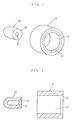
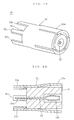
- Fig. 1 is a perspective view of the binding members of the first embodiment according to the present invention.
- Fig. 2 is a sectional view of the binding members of the first embodiment.
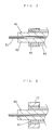
- Fig. 3 is a sectional view of the coaxial cable used in the first embodiment. The coverings of the coaxial cable are removed.
- Fig. 4 is a sectional view showing the binding member of the first embodiment covering the outer conductor of the coaxial cable of Fig. 3.
- Fig. 5 is a sectional view showing the binding members of the first embodiment covering both the outer conductor and the centered conductor of the coaxial cable of Fig. 3.
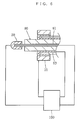
- Fig. 6 is a schematic diagram showing another embodiment of the method of connecting the binding members of the first embodiment to the coaxial cable.
- Fig. 7 is a sectional view showing the binding members of the first embodiment, which are connected to a printed circuit board.
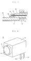
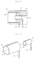
- Fig. 8 is a perspective view of the electric connector of the second embodiment.
- Fig. 9 is a sectional view of the electric connector of the second embodiment.
- Fig. 10 is a perspective view of the electric contacts of the electric connector of the second embodiment.
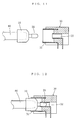
- Fig. 11 is a sectional view showing the electric connector of the second embodiment before the connection of the coaxial cable to which the binding members are connected or which is covered by the binding members.
- Fig. 12 is a sectional view showing the electric connector of the second embodiment after the connection of the coaxial cable to which the binding members are connected or which is covered by the binding members.
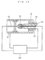
- Fig. 13 is a schematic diagram showing another embodiment of the method of connecting the binding members to the electric connector of the second embodiment.
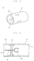
- Fig. 14 is perspective view of the electric connector of the third embodiment.
- Fig. 15 is a sectional view of the electric connector of the third embodiment.
- Fig. 16 is a sectional view of the electric connector of the third embodiment before the connection of the coaxial cable to which the binding members are connected or which is covered by the binding members.
- Fig. 17 is a sectional view of the electric connector of the third embodiment after the connection of the coaxial cable to which the binding members are connected or which is covered by the binding members.
- Fig. 18 is a schematic diagram showing another embodiment of the method of connecting the binding members to the electric connector of the third embodiment.
- Fig. 19 is a perspective view of the counterpart connector which is connected to the electric connector of the third embodiment.
- Fig. 20 is a sectional view of the counterpart connector which is connected to the electric connector of the third embodiment.
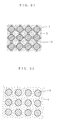
- Fig. 21 is a schematic structural diagram of the lead-free ultrahigh-conductive plastic used in the embodiments.
- Fig. 22 is a schematic structural diagram of the conventional plastic wherein powder of a metal that does not melt is kneaded in a resin.
- binding member for coaxial cable and the electric connector for coaxial cable both using resin solder and the method of connecting the binding member to coaxial cable or the electric connector according to the present invention will be described.
- This lead-free ultrahigh-conductive plastic is a conductive resin composite, which comprises a thermoplastic resin, a lead-free solder that can be melted in the plasticated thermoplastic resin, and powder of a metal that assists fine dispersion of the lead-free solder in the thermoplastic resin or a mixture of the powder of the metal and short fibers of a metal.
- This lead-free ultrahigh-conductive plastic includes those wherein lead-free solder parts that are finely dispersed in the above-mentioned thermoplastic resin are continuously connected to each other in the entire resin.
- the above-mentioned lead-free ultrahigh-conductive plastic includes those of which above-mentioned conductive resin composite has such a conductivity that the volume resistivity thereof is as low as 10 -3 ⁇ ⁇ cm or under.
- the synthetic resin to be used for this lead-free ultrahigh-conductive plastic is not specifically limited, and those that have been used conventionally can be used. However, from the viewpoints of ease in molding and some other physical properties required, it is preferable to use a thermoplastic resin.
- the metal to be used for this lead-free ultrahigh-conductive plastic must be a lead-free metal that can half melt when the synthetic resin composite containing the metal is heat-plasticated.
- the heat plastication temperature of thermoplastic resin is normally 350°C or under, low-melting-point metals having a melting point below the above-mentioned plastication temperature are preferable.
- the metal may be a pure metal or an alloy.
- the above-mentioned metal include zinc (Zn), tin (Sn), bismuth (Bi), aluminum (Al), cadmium (Cd), indium (In) and their alloys.
- preferred alloys among them include low-melting-point alloys such as Sn-Cu, Sn-Zn, Sn-Al and Sn-Ag.
- Metals in powdery form for assisting dispersion of the solder include copper (Cu), nickel (Ni), aluminum (Al), chromium (Cr) and their alloys all in powdery form.
- the finer is the particle diameter of the metal powder, the finer is the dispersion of the solder after kneading. However, it is not necessary to provide powder of a common particle diameter. Powder of a metal having a distribution of particle diameters can be used.
- the usage of the metal components in the above-mentioned lead-free ultrahigh-conductive plastic is from 30 to 75 % and preferably from 45 to 65 % in volume ratio to the entire conductive resin composite.
- the above-mentioned lead-free ultrahigh-conductive plastic uses a resin and a low-melting-point alloy (lead-free solder) which does not contain lead from the viewpoint of environment.
- the lead-free solder being metal components can be dispersed finely throughout the resin.
- the dispersed solder fractions are kept connected continuously to each other. This connection is not just a contact but a junction between solder fractions. As the conductivity thus achieved differs from that obtained by contacts among metal fractions, even if the molding is heated to a high temperature, the junctions will not break, thus the molding stably exhibits low resistance.
- this material When this material is to be formed by injection molding, as the metal components are partly half-melted and the lead-free solder is finely dispersed, the material can be formed by injection molding into fine configurations although the material contains a large amount of metal components. Hence binding members and the like can be formed by processes of injection molding alone. Moreover, as no plating is required, a conductive part of low resistance can be formed inside the injection molding.
- ABS resin produced by Toray; Toyolac 441
- lead-free solder produced by Fukuda Kinzoku Hakufun Kogyo; Sn-Cu-Ni-AtW-150
- copper powder produced by Fukuda Kinzoku Hakufun Kogyo; FCC-SP-77, mean particle diameter 10 ⁇ m
- the kneaded material was pelletized by a plunger extrusion pelletizer (Toshin make, Model TP60-2) at the dies temperature ranging from 200 to 240°C to produce pellets. These pellets were used to make injection molding into molds by an injection molding machine (Kawaguchi Tekko make, KS-10B). The preset temperature was from 230 to 280°C, and the mold temperature was from the ordinary temperature to 150 °C. The injection moldings obtained showed no sign of segregation of metal, and their surfaces were even.
- ABS resin produced by Toray; Toyolac 441
- lead-free solder produced by Fukuda Kinzoku Hakufun Kogyo; Sn-Cu-Ni-AtW-150
- 10 % by volume of copper powder produced by Fukuda Kinzoku Hakufun Kogyo; FCC-SP-77, mean particle diameter 10 ⁇ m
- FCC-SP-77 mean particle diameter 10 ⁇ m
- the kneaded material was pelletized by the plunger extrusion pelletizer (Toshin make, Model TP60-2) at the dies temperature ranging from 200 to 240°C to produce pellets. These pellets were used to make injection molding into molds by the injection molding machine (Kawaguchi Tekko make, KS-10B). The preset temperature of the machine was from 230 to 280°C, and the mold temperature was from the ordinary temperature to 150 °C. The injection moldings obtained showed no sign of segregation of metal, and their surfaces were even. Observation, under an optical microscope, of the state of dispersion of the solder showed that the solder was evenly dispersed throughout the resin and solder fractions were about 100 ⁇ m or under in size. The volume resistivity of this specimen was on the order of 4 x 10 -5 ⁇ ⁇ cm.
- the lead-free solder could be dispersed finely throughout the resins, and even when a large volume of metal components as high as 65 % by volume were mixed, a kneaded material that did not show any segregation, under heating, of metals from the resin was obtained successfully.
- the solder fractions were continuous to each other in this lead-free ultrahigh-conductive plastic, the conductivity of the plastic did not show any deterioration even when the temperature changed, thus the plastic stably exhibited high conductivity.
- injection molding the plastic was successfully molded into fine configurations without any clogging.
- Fig. 21 is a schematic structural diagram of the above-mentioned lead-free ultrahigh-conductive plastic. As shown in this diagram, in this lead-free ultrahigh-conductive plastic, the lead-free solders 1 are connected to each other by the solders 2 which are melted in the plastic 3. Hence the lead-free solders 1 are junctioned to each other and the conductivity is high and the reliability of the connection is high.
- the lead-free ultrahigh-conductive plastic shows a low resistance, does not exhibit deterioration in conductivity in a variety of environments, and has a high reliability.
- the lead-free solder being the metal components can be dispersed finely throughout the resin.
- the dispersed solder fractions are kept connected continuously to each other. This connection is not just a contact but a junction between solder fractions. As the conductivity thus achieved differs from that obtained by contacts among metal fractions, even if the molding is heated to a high temperature, the junctions will not break, thus the molding stably exhibits low resistance.
- this material When this material is to be formed by injection molding, as the metal components are partly half-melted and the lead-free solder is finely dispersed, the material can be formed by injection molding into fine configurations although the material contains a large amount of metal components. Hence the binding members and the like can be formed by processes of injection molding alone. Moreover, as no plating is required, a conductive part of low resistance can be formed inside the frame (injection molding).
- the first embodiment is a binding member for axial cable using the resin solder.
- the coaxial cable 80 comprises a centered conductor 81, an insulating covering 82 which covers the centered conductor 81, an outer conductor 83 which is braided strands and covers the outside of the insulating covering 82, and an insulating covering 84 which covers the outer conductor 83.
- the binding members include a binding member 10 for the outer conductor 83 and a binding member 20 for the centered conductor 81.
- the binding member 10 for the outer conductor 83 is formed into a tubular piece which covers the outer conductor 83 being exposed from the insulating cover 84.
- the configuration of the binding member 10 is not limited provided that it is tubular. Here it is a cylinder with a through hole 11. A chamfered part 12 is provided, if necessary, in one opening of the through hole 11. This chamfered part 12 guides the end of the coaxial cable 80 into the through hole 11.
- the binding member 20 for the centered conductor 81 is formed into a tubular piece which covers the centered conductor 81 being exposed from the insulating covering 82.
- the configuration of the binding member 80 is not limited provided that it is tubular.
- binding members 10, 20 are made of the lead-free ultrahigh-conductive plastic being the conductive resin composite.
- binding members 10, 20 The method of use of these binding members 10, 20 will be described.
- an end of the insulating covering 84 is removed to expose the outer conductor 83, and the exposed outer conductor 83 is reversed to cover the new end of the insulating covering 84.
- the exposed outer conductor 83 may be left as it is.
- the end of the insulating covering 82 is removed to expose the end of the centered conductor 81.
- the binding member 10 is fitted to cover the outer conductor 83 which is exposed from the insulating covering 84.
- the lead-free solder being contained in the lead-free ultrahigh-conductive plastic of the binding member 10 will melt out to stick to the outer conductor 83.
- the binding member 10 will be connected to the outer connector 83.
- the binding member 20 is fitted to cover the centered conductor 81 which is exposed from the insulating covering 82.
- the lead-free solder being contained in the lead-free ultrahigh-conductive plastic of the binding member 20 will melt out to stick to the centered conductor 81.
- the binding member 20 When the solder cools and solidifies, the binding member 20 will be connected to the centered conductor 81.
- the above-mentioned heating is effected by, for example, blowing hot air or irradiating high frequency waves or laser beams to give thermal energy.
- the binding members 10, 20 being connected to the coaxial cable 80 are placed on electric connecting devices or a printed circuit board and the contacting parts between them are heated, the lead-free solder of the lead-free ultrahigh-conductive plastic of the binding members 10, 20 will melt out and stick to the electric connecting devices or the printed circuit board. When the solder cools and solidifies, the binding members 10, 20 will be connected to the electric connecting devices or the printed circuit board. This in turn will connect the coaxial cable 80 to the electric connecting devices or the printed circuit board.
- the above-mentioned heating is effected by, for example, blowing hot air or irradiating high frequency waves or laser beams to give thermal energy.
- Fig. 7 shows an example of use wherein the binding members 10, 20 are connected to a printed circuit board 90.
- the binding member 10 for the outer conductor 83 is connected to the grounding conductor 91 of the printed circuit board 90, and the binding member 20 for the centered conductor 81 is connected to the signal conductor 92 of the printed circuit board 90. Examples of use wherein the binding members 10, 20 are connected to electric connecting devices such as terminals, electric contacts, etc. will be described later.
- the binding members of the first embodiment are used, when the axial cable 80 is to be connected to electric connecting devices or the printed circuit board 90, no work of separately; applying solder will be required. Hence, even if an adequate space for the soldering work can not be provided, the coaxial cable 80 can be easily connected to the electric connecting devices or the printed circuit board 90. Moreover, as solder quality control, temperature control and the like are not required, the control man-hour is reduced correspondingly.
- the binding member 10 or 20 circumferentially covers the outer conductor 83 or the centered conductor 81 to prevent the outer conductor 83 or the centered conductor 81 from being disturbed, the outer conductor 83 or the centered conductor 81 can be easily connected to the electric connecting device or the printed circuit board 90 and the workability is good.
- the binding members 10, 20 have conductivity, the shielding performance of the signal line is ensured. Further, the connection of a very fine wire can be done by an automatic machine, and the productivity is enhanced and the cost is reduced.
- the lead-free ultrahigh-conductive plastic exhibits high conductivity, as high as 10 -3 ⁇ ⁇ cm or under in volume resistivity. Hence the electric resistance of the binding members 10, 20 can be reduced.
- the lead-free ultrahigh-conductive plastic After the connection of the coaxial cable 80, when electricity is passed at a normal level, the lead-free ultrahigh-conductive plastic will not melt due to heat generation. Moreover, in comparison with the technology of MID wherein a conductive plated layer is formed on the surface of an insulator, the lead-free ultrahigh-conductive plastic provides the conductor with a larger cross-sectional area and a larger volume. Hence the resistance of the conductor can be reduced and the heat dissipation is better. This in turn allows passage of a larger current. As the lead-free ultrahigh-conductive plastic can be formed by injection molding, the binding members 10, 20 can be directly formed by injection molding. As it has a greater freedom of molding, the binding members 10, 20 can be molded to a variety of configurations according to their applications. This makes it easier to obtain impedance matching.
- FIG. 6 Another embodiment of the method of connecting the binding members 10, 20 to the coaxial cable 80 will be described.
- the binding member 10 is placed to cover the outer conductor 83 being exposed from the insulating covering 84.
- electricity is passed between the binding member 10 and the outer conductor 83 by a power source 100 to melt the lead-free solder which is contained in the binding member 10 to connect the binding member 10 to the outer conductor 83.
- the binding member 20 is placed to cover the centered conductor 81 being exposed from the insulating covering 82.
- electricity is passed between the binding member 20 and the centered conductor 81 by the power source 100 to melt the lead-free solder being contained in the binding member 20 to connect the binding member 20 to the centered conductor 81.
- the binding members 10, 20 When this method is used, as the binding members 10, 20 generate heat by themselves, even if it is difficult to externally heat the contacting parts of both the binding members 10, 20 and the conductors 83, 81 of the coaxial cable 80, the binding members 10, 20 can be connected to the conductors 83, 81 of the coaxial cable 80.
- Fig. 8 through Fig. 10 show an electric connector for coaxial cable being the second embodiment of the present invention.
- This electric connector 30 is mounted on a printed circuit board.
- This electric connector 30 comprises a first electric contact 31, a second electric contact 32 and a housing 33 which insulates and couples these electric contacts 31, 32.
- the first electric contact 31 is made of a conductor such as a copper alloy and has a receiving port 31a into which the binding member 10 for the outer conductor 83 is inserted.
- the configuration of the receiving port 31a is not limited provided that the binding member 10 can be inserted into the port 31a.
- the first electric contact 31 is formed into a tubular piece and the opening in one end thereof is used as the receiving port 31a.
- a lead 31b for connecting to another member is provided at the other end of the first electric contact 31.
- the second electric contact 32 is made of a conductor such as a copper alloy and has a receiving port 32a into which the binding member 20 for the centered conductor 81 is inserted.
- the configuration of the receiving port 32a is not limited provided that the binding member 20 can be inserted into the receiving port 32a.
- the second electric contact 32 is formed into a tubular piece and the'opening in one end thereof is used as the receiving port 32a.
- a lead 32b for connecting to another member is provided at the other end of the second electric contact 32.
- the housing 33 is made of an insulator, and the first and second electric contacts 31, 32 are fitted into the housing 33 or the first and second electric contacts 31, 32 and the housing 33 are formed integrally. The respective leads 31b, 32b are led out of the housing 33.
- this electric connector 30 The method of use of this electric connector 30 will be described.
- the binding member 10, which connects with or covers the outer conductor 83 of the coaxial cable 80 is inserted into the receiving port 31a of the first electric contact 31 of the electric connector 30, and the binding member 20, which connects with or covers the centered conductor 81 of the coaxial cable 80, is inserted into the receiving port 32a of the second electric contact 32.
- the contacting parts of the first and second electric contacts 31, 32 and the binding members 10, 20 are heated, the lead-free solder being contained in the lead-free ultrahigh-conductive plastic of the binding members 10, 20 will melt out and stick to the first and second electric contacts 31, 32.
- the binding members 10, 20 When the solder cools and solidifies, the binding members 10, 20 will be connected to the first and second electric contacts 31, 32, and this will connect the coaxial cable 80 to the electric connector 30.
- the expression "the,binding member connects with or covers the conductor” is used because, in the stage of inserting the binding member into the receiving port of the electric contact, the binding member may be either in the state of being connected to the conductor by heating and cooling or in the state of just covering the conductor.
- the above-mentioned heating is made by, for example, blowing hot air or irradiating high frequency waves or laser beams to give thermal energy.
- the coaxial cable 80 when the coaxial cable 80 is to be connected to the electric connector 30, the work of separately applying solder is not required. Accordingly, even if an adequate space for the soldering work can not be provided, the coaxial cable 80 can be easily connected to the electric connector 30. Moreover, as solder quality control, temperature control and the like are not required, the control man-hour is reduced correspondingly. Furthermore, as the binding member 10 or 20 circumferentially covers the outer conductor 83 or the centered conductor 81 to prevent the outer conductor 83 or the centered conductor 81 from being disturbed, the outer conductor 83 or the centered conductor 81 can be easily connected to the electric connector 30.
- the lead-free ultrahigh-conductive plastic exhibits high conductivity, as'high as 10 -3 ⁇ ⁇ cm or under in volume resistivity. Hence the electric resistance of the wiring harness comprising the coaxial cable 80 and the electric connector 30 can be reduced. After the connection of the coaxial cable 80, when electricity is passed at a normal level, the lead-free ultrahigh-conductive plastic will not melt due to heat generation.
- the lead-free ultrahigh-conductive plastic provides the conductor with a larger cross-sectional area and a larger volume. Hence the resistance of the conductor can be reduced and the heat dissipation is better. This in turn allows passage of a larger current in the wiring harness.
- the electric contact may be made of a conductor.
- the present invention includes embodiments wherein the electric contact is made of, for example, the lead-free ultrahigh-conductive plastic.
- the electric contact 31, 32 is made of a material of which strength and elasticity are higher than those of the lead-free ultrahigh-conductive plastic, for example a metal, the strength and elasticity of the electric contact 31, 32 will be secured, and the durability against repeated insertion and extraction will be improved.
- FIG. 13 Another embodiment of the method of connecting these binding members 10, 20 to the electric connector 30 will be described.
- the binding member 10, which connects with or covers the outer conductor 83 is inserted into the first electric contact 31.
- electricity is passed between the first electric contact 31 and the outer conductor 83 by a power source 100 to melt the lead-free solder being contained in the binding member 10 to connect the binding member 10 to the first electric contact 31.
- the binding member 20, which connects with or covers the centered conductor 81 is inserted into the second electric contact 32.
- the binding members 10, 20 When this method is used, as the binding members 10, 20 generate heat by themselves, even if it is difficult to externally heat the contacting parts of both the binding members 10, 20 and the electric contacts 31, 32, the binding members 10, 20 can be connected to the electric contacts 31, 32.
- Fig. 14 and Fig. 15 show the third embodiment being an electric connector for coaxial cable.
- This electric connector 40 is connected to a counterpart connector 50, which will be described later.
- the electric connector 40 comprises a first electric contact 41, a second electric contact 42 and a housing 43, which insulates and couples these electric contacts 41, 42.
- the first electric contact 41 is made of a conductor, for example, a copper alloy, and has a receiving port 41a into which the binding member 10 for the outer conductor 83 is inserted.
- the configuration of the receiving port 41a is not limited provided that the binding member 10 can be inserted into the receiving port 41a.
- the first electric contact 41 is formed into a tubular piece and the opening at one end thereof is used as the receiving port 41a.
- the other end thereof is used as the contacting part 41b to be connected to the counterpart connector 50.
- a plate-shaped housing 43 which is formed of an insulator, is provided inside the first electric contact 41.
- the second electric contact 42 is made of a conductor, for example, a copper alloy, and is made to pierce the housing 43.
- the second electric contact 42 is fixed onto the housing 43.
- the second electric contact 42 has, at one end thereof, a receiving port 42a into which the binding member 20 for the centered conductor 81 is inserted.
- the configuration of the receiving port 42a is not limited provided that the binding member 20 can be inserted into the receiving port 42a.
- the second electric contact is formed into a rod, and one end thereof is formed into a cup which is used as the receiving port 42a.
- the other end of the second electric contact 42 is used as the contacting part 42b for connecting with the counterpart connector 50.
- this electric connector 40 The method of use of this electric connector 40 will be described.
- the binding member 10, which connects with or covers the outer conductor 83 of the coaxial cable 80 is inserted into the receiving port 41a of the first electric contact 41 of the electric connector 40, and the binding member 20, which connects with or covers the centered conductor 81 of the coaxial cable 80 is inserted into the receiving port 42a of the second electric contact 42.
- the contacting parts of the first and second electric contacts 41, 42 and the binding parts 10, 20 are heated, the lead-free solder being contained in the lead-free ultrahigh-conductive plastic of the binding members 10, 20 will melt out to stick to the first and second electric contacts 41, 42.
- the binding members 10, 20 When the solder cools and solidifies, the binding members 10, 20 will be connected to the first and second electric contacts 41, 42, and this in turn will connect the coaxial cable 80 to the electric connector 40.
- the above-mentioned heating is made by, for example, blowing hot air or irradiating high frequency waves or laser beams to give thermal energy.
- Fig. 18 shows another embodiment of the method of connecting the binding members 10, 20 to the electric connector 40 of the third embodiment.
- This method is similar to the method of connecting the binding members 10, 20 to the electric connector 30 of the second embodiment, and can be similarly described by substituting the first electric contact 31 with the first electric contact 41, and the second electric contact 32 with the second electric contact 42. Functions and effects similar to those of the second embodiment can be obtained.
- Fig. 19 and Fig. 20 show the counterpart connector 50 to which the electric connector 40 of the third embodiment is connected.
- This counterpart connector 50 is mounted on a printed circuit board.
- the counterpart connector 50 comprises a first electric contact 51, a second electric contact 52 and a housing 53 which insulates and couples these electric contacts 51, 52.
- the first electric contact 51 is made of a conductor, for example, a copper alloy and has a contacting part 51a into which the first electric contact 41 of the above-mentioned electric connector 40 is inserted.
- the configuration of the contacting part 51a is not limited provided that the first electric contact 41 can be inserted into the part 51a.
- the first electric contact 51 is formed into a tubular piece and the opening in one end thereof is used as the contacting part 51a.
- Leads 51b for mounting on the printed circuit board are formed to protrude from the other end thereof.
- the housing 53 being formed of an insulator is provided inside the first electric contact 51.
- a gap to receive the first electric contact 41 is open between the first electric contact 51 and the housing 53.
- Slits are made in the first electric contact 51 from the side of the contacting part 51a in the axial direction.
- Each portion between a slit and an adjacent slit functions as a leaf spring.
- the second electric contact 52 is made of a conductor, for example, a copper alloy, and is made to pierce the housing 53.
- the second electric contact 52 is fixed to the housing 53.
- the second electric contact 52 has, at one end thereof, a contacting part 52 which fits with the second electric contact 42 of the above-mentioned electric connector 40.
- the configuration of the contacting part 52a is not limited provided that the second electric contact 42 can be inserted into the contacting part 52a.
- the second electric contact 52 is formed into a rod, and one end thereof is formed into a cup which is used as the contacting part 52a. The other end of the second electric contact 52 is used as the lead 52b for mounting on the printed circuit board.
- the present invention includes embodiments wherein features of the above-mentioned embodiments are combined.
- the present invention is also applicable to coaxial cables which have a plurality of centered cables and their insulating coverings.
- a coaxial cable 80 comprises a plurality of centered conductors 81, a plurality of insulating coverings which cover the respective centered conductors 81, an outer conductor 83 which consists of braided strands and covers the outside of the above-mentioned plurality of insulating coverings 82, and an insulating covering 84 which covers the outer conductor 83.
- binding members of the first embodiment are to be used for this coaxial cable 80
- one binding member 10 is used for the outer conductor 83
- a plurality of binding members 10 are used for the centered conductors 81.
- the electric connector 30 of the second embodiment or the electric connector 40 of the third embodiment is used for this coaxial cable 80
- a plurality of the second electric connectors 32 or 42 are used.
- Coaxial cables of such a kind are exemplified by Twinax.
- the electric connector for coaxial cable comprises a first electric contact, which is made of a conductor and has a receiving port into which the above-mentioned binding member for the outer conductor is inserted, a second electric contact, which is made of a conductor and has a receiving port into which the above-mentioned binding member for the centered conductor is inserted, and a housing, which insulates and couples these electric contacts.
- the binding member of the present invention which connects to or covers the outer conductor of the coaxial cable, is inserted into the receiving port of the first electric contact of this electric connector, and the binding member of the present invention, which connects to or covers the centered conductor of the coaxial cable, is inserted into the receiving port of the second electric contact.
- the coaxial cable when the coaxial cable is to be connected to the electric' connector, the work of separately applying solder is not required. Accordingly, even if an adequate space for the soldering work can not be provided, the coaxial cable can be easily connected to the electric connector. Moreover, as solder quality control, temperature control and the like are not required, the control man-hour is reduced correspondingly. Furthermore, as the binding member circumferentially covers the outer conductor or the centered conductor to prevent the outer conductor or the centered conductor from being disturbed, the outer conductor or the centered conductor can be easily connected to the electric connector. Thus the workability is good, and as the binding members have conductivity, the shielding performance of the signal line is ensured.
- connection of a very fine wire can be done by an automatic machine, and the productivity is enhanced and the cost is reduced.
- the lead-free ultrahigh-conductive plastic exhibits high conductivity, as high as 10 -3 ⁇ ⁇ cm or under in volume resistivity. Hence the electric resistance of the wiring harness comprising the coaxial cable and the electric connector can be reduced. After the connection of the coaxial cable, when electricity is passed at a normal level, the lead-free ultrahigh-conductive plastic will not melt due to heat generation. Moreover, in comparison with the technology of MID wherein a conductive plated layer is formed on the surface of an insulator, the lead-free ultrahigh-conductive plastic provides the conductor with a larger cross-sectional area and a larger volume.
- this electric connector for coaxial cable is suitable as the electric connector for connecting the coaxial cable via the above-mentioned binding member.
- the method of connecting the binding member to the coaxial cable is to place the binding member to cover the outer conductor or the centered conductor which is exposed from the insulating covering, pass electricity between the binding member and the outer conductor or the centered conductor of the coaxial cable to melt the lead-free solder being contained in the binding member and connect the binding member to the outer conductor or the centered conductor.
- the binding member When this method is used, as the binding member generates heat by itself, even if it is difficult to externally heat the contacting parts of both the binding member and the conductor of the coaxial cable, the binding member can be connected to the conductor of the coaxial cable.
- the method of connecting the binding member to the electric connector is the method of connecting the above-mentioned binding member, which connects to or covers the outer conductor or the centered conductor, to the above-mentioned electric connector, and is to insert the binding member, which connects to or covers the outer conductor or the centered conductor, into the first or second electric contact, pass electricity between the first or second electric contact and the outer conductor or the centered conductor to melt the lead-free solder being contained in the binding member and connect the binding member to the first or second electric contact.
- the binding member When this method is used, as the binding member generates heat by itself, even if it is difficult to externally heat the contacting parts of both the binding member and the electric contact, the binding member can be connected to the electric contact.
Landscapes
- Coupling Device And Connection With Printed Circuit (AREA)
- Multi-Conductor Connections (AREA)
- Cable Accessories (AREA)
- Compositions Of Macromolecular Compounds (AREA)
- Manufacturing Of Electrical Connectors (AREA)
- Processing Of Terminals (AREA)
- Connections Effected By Soldering, Adhesion, Or Permanent Deformation (AREA)
Applications Claiming Priority (2)
| Application Number | Priority Date | Filing Date | Title |
|---|---|---|---|
| JP2001102645A JP2002298995A (ja) | 2001-03-30 | 2001-03-30 | 樹脂ハンダを用いた同軸ケーブルの結束部材及び同軸ケーブルの電気コネクタ並びに結束部材の同軸ケーブル又は電気コネクタへの接続方法 |
| JP2001102645 | 2001-03-30 |
Publications (2)
| Publication Number | Publication Date |
|---|---|
| EP1246300A2 true EP1246300A2 (de) | 2002-10-02 |
| EP1246300A3 EP1246300A3 (de) | 2003-11-26 |
Family
ID=18955811
Family Applications (1)
| Application Number | Title | Priority Date | Filing Date |
|---|---|---|---|
| EP20020007084 Withdrawn EP1246300A3 (de) | 2001-03-30 | 2002-03-27 | Bindungselement für koaxiales Kabel und ein elektrischer Verbinder für koaxiales Kabel, beide unter Verwendung von Harz-Lötpaste, und Verfahren zur Verbindung |
Country Status (6)
| Country | Link |
|---|---|
| US (1) | US6974615B2 (de) |
| EP (1) | EP1246300A3 (de) |
| JP (1) | JP2002298995A (de) |
| KR (1) | KR20020077267A (de) |
| CN (1) | CN1379502A (de) |
| TW (1) | TW536854B (de) |
Cited By (3)
| Publication number | Priority date | Publication date | Assignee | Title |
|---|---|---|---|---|
| EP1562265A1 (de) * | 2004-02-04 | 2005-08-10 | Delphi Technologies, Inc. | Koaxialkabelendstück |
| EP1508941A3 (de) * | 2003-08-16 | 2008-03-05 | Rainer Bicking | Elektrischer Leiter mit einem Lotdepot an einem Kontaktabschnitt |
| WO2009132735A1 (de) * | 2008-04-30 | 2009-11-05 | Md Elektronik Gmbh | Elektrisches kabel sowie verfahren und vorrichtung zu dessen herstellung |
Families Citing this family (21)
| Publication number | Priority date | Publication date | Assignee | Title |
|---|---|---|---|---|
| US7244890B2 (en) | 2001-02-15 | 2007-07-17 | Integral Technologies Inc | Low cost shielded cable manufactured from conductive loaded resin-based materials |
| JP2003282197A (ja) * | 2002-03-25 | 2003-10-03 | Fujitsu Ltd | 同軸コネクタ及びその製造方法並びに超伝導装置 |
| JP4084079B2 (ja) | 2002-05-07 | 2008-04-30 | 日本圧着端子製造株式会社 | コネクタ構造 |
| KR100716413B1 (ko) | 2006-02-13 | 2007-05-11 | 엘에스전선 주식회사 | 열전재료를 이용한 전력케이블의 접합 방법 |
| JP2008198456A (ja) * | 2007-02-13 | 2008-08-28 | Neomax Material:Kk | 導電材の接続部材及びその接続方法 |
| JP5045547B2 (ja) * | 2008-05-19 | 2012-10-10 | マックス株式会社 | 鉄筋結束機 |
| JP4858488B2 (ja) * | 2008-05-19 | 2012-01-18 | マックス株式会社 | 鉄筋結束機 |
| US8365404B2 (en) | 2010-11-22 | 2013-02-05 | Andrew Llc | Method for ultrasonic welding a coaxial cable to a coaxial connector |
| US8826525B2 (en) * | 2010-11-22 | 2014-09-09 | Andrew Llc | Laser weld coaxial connector and interconnection method |
| US8887388B2 (en) | 2010-11-22 | 2014-11-18 | Andrew Llc | Method for interconnecting a coaxial connector with a solid outer conductor coaxial cable |
| JP5838819B2 (ja) * | 2012-01-12 | 2016-01-06 | 住友電気工業株式会社 | 電気コネクタ付ケーブル及び電気コネクタ付ケーブルの製造方法 |
| JP6327531B2 (ja) | 2012-11-30 | 2018-05-23 | エレクトリック パワー リサーチ インスチテュート インコーポレイテッド | 表面ドーピングによる電気的接触導電率の改善 |
| US10239164B2 (en) * | 2013-10-23 | 2019-03-26 | Onanon, Inc. | Robotic wire termination system |
| JP2016094542A (ja) * | 2014-11-14 | 2016-05-26 | 内浜化成株式会社 | ポリプロピレン樹脂組成物およびこのポリプロピレン樹脂組成物からなる電磁波シールド部材 |
| DE102015012906A1 (de) * | 2015-02-27 | 2016-09-01 | Gentherm Gmbh | Hülse, Kontaktier-Einrichtung und Verfahren zum Schweißen von dünnen strangförmigen Leitern mittels Ultraschall |
| RU2654374C1 (ru) * | 2016-06-15 | 2018-05-18 | Руслан Борисович Аношин | Макетная плата |
| JP7344650B2 (ja) * | 2019-02-25 | 2023-09-14 | オリンパス株式会社 | 撮像装置、撮像装置を含む内視鏡装置、および撮像装置を含む移動体 |
| US10886685B2 (en) * | 2019-03-08 | 2021-01-05 | Onanon, Inc. | Preformed solder-in-pin system |
| JPWO2021059903A1 (de) * | 2019-09-27 | 2021-04-01 | ||
| US10868401B1 (en) | 2020-03-04 | 2020-12-15 | Onanon, Inc. | Robotic wire termination system |
| CN115733023A (zh) * | 2022-12-02 | 2023-03-03 | 深圳市拓普联科技术股份有限公司 | 连接器的加工工艺 |
Family Cites Families (54)
| Publication number | Priority date | Publication date | Assignee | Title |
|---|---|---|---|---|
| GB256377A (en) * | 1925-07-02 | 1926-08-12 | George Earl Vicary | A self soldering nipple for fixing on control wires and cables of motor cycles and for other similar purposes |
| US3914081A (en) | 1969-12-29 | 1975-10-21 | Katashi Aoki | Apparatus for injection molding two-colored products |
| US3660726A (en) | 1970-10-12 | 1972-05-02 | Elfab Corp | Multi-layer printed circuit board and method of manufacture |
| US3822107A (en) | 1970-11-20 | 1974-07-02 | Engel Kg L | Improvements in or relating to an injection mold |
| US3978378A (en) | 1973-02-12 | 1976-08-31 | The Dow Chemical Company | Articles having electroconductive components of highly electroconductive resinous compositions |
| US3971610A (en) | 1974-05-10 | 1976-07-27 | Technical Wire Products, Inc. | Conductive elastomeric contacts and connectors |
| US4315724A (en) | 1979-12-19 | 1982-02-16 | Kamaya Kagaku Kogyo Co., Ltd. | Process and machine for multi-color injection molding |
| US4398785A (en) | 1981-09-28 | 1983-08-16 | Essex Group, Inc. | Electrical connector and method of making same |
| US5129143A (en) | 1982-11-29 | 1992-07-14 | Amp Incorporated | Durable plating for electrical contact terminals |
| US4926548A (en) | 1984-10-17 | 1990-05-22 | Amp Incorporated | Select solder slot termination method |
| US4666547A (en) | 1985-03-29 | 1987-05-19 | Snowden Jr Thomas M | Electrically conductive resinous bond and method of manufacture |
| US4778556A (en) | 1986-04-21 | 1988-10-18 | Unisys Corporation | Apparatus for correcting printed circuit boards |
| JPS6332881A (ja) | 1986-07-25 | 1988-02-12 | 日本テキサス・インスツルメンツ株式会社 | Icソケツト |
| DD276951A1 (de) | 1987-08-04 | 1990-03-14 | Seefahrt Inghochschule | Verbindungselement oder fassung nach dem ssc-prinzip |
| JPH055657Y2 (de) | 1988-05-10 | 1993-02-15 | ||
| US4863392A (en) | 1988-10-07 | 1989-09-05 | Amerace Corporation | High-voltage loadbreak bushing insert connector |
| JP2597015B2 (ja) | 1989-09-29 | 1997-04-02 | ホーヤ株式会社 | ガラス溶融装置の溶融ガラス流出量調節方法および装置 |
| US5163856A (en) | 1989-10-20 | 1992-11-17 | Metcal, Inc. | Multipin connector |
| DE4012061A1 (de) | 1990-04-10 | 1991-10-17 | Mittweida Ing Hochschule | Loesungsmittelfreie isotrope leit- und klebepaste mit eingelagerten elektrisch leitfaehigen partikeln |
| US5249355A (en) | 1991-10-31 | 1993-10-05 | Hughes Aircraft Company | Method of fabricating a multilayer electrical circuit structure |
| US5232377A (en) * | 1992-03-03 | 1993-08-03 | Amp Incorporated | Coaxial connector for soldering to semirigid cable |
| US5347711A (en) | 1992-07-15 | 1994-09-20 | The Whitaker Corporation | Termination of multi-conductor electrical cables |
| GB9219448D0 (en) * | 1992-09-14 | 1992-10-28 | Raychem Sa Nv | Termination device and method |
| US5497546A (en) | 1992-09-21 | 1996-03-12 | Matsushita Electric Works, Ltd. | Method for mounting lead terminals to circuit board |
| US5402088A (en) | 1992-12-03 | 1995-03-28 | Ail Systems, Inc. | Apparatus for the interconnection of radio frequency (RF) monolithic microwave integrated circuits |
| US5357074A (en) | 1993-08-17 | 1994-10-18 | The Whitaker Corporation | Electrical interconnection device |
| US5427546A (en) | 1993-12-16 | 1995-06-27 | Methode Electronics, Inc. | Flexible jumper with snap-in stud |
| US5590460A (en) | 1994-07-19 | 1997-01-07 | Tessera, Inc. | Method of making multilayer circuit |
| US5580271A (en) | 1994-09-08 | 1996-12-03 | The Whitaker Corporation | SCSI cable with termination circuit and method of making |
| JPH08148240A (ja) | 1994-09-20 | 1996-06-07 | Whitaker Corp:The | コネクタ |
| US5772454A (en) | 1995-11-03 | 1998-06-30 | The Whitaker Corporation | Wire to board contact terminal |
| JPH09274972A (ja) | 1996-02-05 | 1997-10-21 | Cable Tec Japan:Kk | ビデオ信号伝送用接続器、並びに該接続器を備えたビデオ信号伝送装置及びビデオ信号伝送システム |
| GB9613046D0 (en) * | 1996-06-21 | 1996-08-28 | Delta Millennia Limited | Making an electrical joint |
| US5800211A (en) * | 1996-06-24 | 1998-09-01 | Augat Inc. | Snap together CATV connector for indoor use |
| JPH1022001A (ja) * | 1996-07-04 | 1998-01-23 | Sumitomo Wiring Syst Ltd | シールド線におけるシールド層の処理構造 |
| DE19638209A1 (de) | 1996-09-19 | 1998-03-26 | Bosch Gmbh Robert | Hochschmelzende elektrisch leitende Verbindung und Verfahren zu deren Herstellung |
| US5898991A (en) | 1997-01-16 | 1999-05-04 | International Business Machines Corporation | Methods of fabrication of coaxial vias and magnetic devices |
| JP3810505B2 (ja) * | 1997-02-28 | 2006-08-16 | 独立行政法人科学技術振興機構 | 導電性プラスチック、それによる導電回路及びその導電回路の形成方法 |
| DE19729327C1 (de) | 1997-07-09 | 1998-10-29 | Wieland Electric Gmbh | Schutzleiterklemme |
| JPH11186688A (ja) | 1997-10-14 | 1999-07-09 | Murata Mfg Co Ltd | ハイブリッドicおよびそれを用いた電子装置 |
| US6179631B1 (en) | 1997-11-21 | 2001-01-30 | Emc Corporation | Electrical contact for a printed circuit board |
| US5959829A (en) | 1998-02-18 | 1999-09-28 | Maxwell Energy Products, Inc. | Chip capacitor electromagnetic interference filter |
| JP3646001B2 (ja) | 1998-02-20 | 2005-05-11 | 本田技研工業株式会社 | アルミニウム材料の耐食性試験方法 |
| US6239385B1 (en) * | 1998-02-27 | 2001-05-29 | Agilent Technologies, Inc. | Surface mountable coaxial solder interconnect and method |
| JPH11312568A (ja) | 1998-04-27 | 1999-11-09 | Yazaki Corp | ステアリング用電気的接続装置における電線とフラットケーブルの接続コネクタ |
| JP3901855B2 (ja) | 1998-08-10 | 2007-04-04 | 矢崎総業株式会社 | シールド端子 |
| EP0994527B1 (de) * | 1998-10-13 | 2004-12-29 | Cabel-Con A/S | Steckverbinder für Koaxialkabel mit Reibungsverschluss |
| US6163957A (en) | 1998-11-13 | 2000-12-26 | Fujitsu Limited | Multilayer laminated substrates with high density interconnects and methods of making the same |
| US6194669B1 (en) | 1999-02-05 | 2001-02-27 | Trw Inc. | Solder ball grid array for connecting multiple millimeter wave assemblies |
| US6159046A (en) * | 1999-07-12 | 2000-12-12 | Wong; Shen-Chia | End connector and guide tube for a coaxial cable |
| US6176744B1 (en) | 1999-10-01 | 2001-01-23 | Motorola, Inc. | Plated plastic connection system and method of making |
| US6388204B1 (en) | 2000-08-29 | 2002-05-14 | International Business Machines Corporation | Composite laminate circuit structure and methods of interconnecting the same |
| US6465084B1 (en) | 2001-04-12 | 2002-10-15 | International Business Machines Corporation | Method and structure for producing Z-axis interconnection assembly of printed wiring board elements |
| US6638607B1 (en) | 2002-10-30 | 2003-10-28 | International Business Machines Corporation | Method and structure for producing Z-axis interconnection assembly of printed wiring board elements |
-
2001
- 2001-03-30 JP JP2001102645A patent/JP2002298995A/ja active Pending
-
2002
- 2002-03-08 TW TW91104416A patent/TW536854B/zh not_active IP Right Cessation
- 2002-03-27 EP EP20020007084 patent/EP1246300A3/de not_active Withdrawn
- 2002-03-28 CN CN02108506A patent/CN1379502A/zh active Pending
- 2002-03-29 KR KR1020020017480A patent/KR20020077267A/ko not_active Withdrawn
- 2002-04-01 US US10/114,198 patent/US6974615B2/en not_active Expired - Fee Related
Cited By (6)
| Publication number | Priority date | Publication date | Assignee | Title |
|---|---|---|---|---|
| EP1508941A3 (de) * | 2003-08-16 | 2008-03-05 | Rainer Bicking | Elektrischer Leiter mit einem Lotdepot an einem Kontaktabschnitt |
| EP1562265A1 (de) * | 2004-02-04 | 2005-08-10 | Delphi Technologies, Inc. | Koaxialkabelendstück |
| US7038134B2 (en) | 2004-02-04 | 2006-05-02 | Delphi Technologies, Inc. | Coaxial cable termination system |
| WO2009132735A1 (de) * | 2008-04-30 | 2009-11-05 | Md Elektronik Gmbh | Elektrisches kabel sowie verfahren und vorrichtung zu dessen herstellung |
| US20110100672A1 (en) * | 2008-04-30 | 2011-05-05 | Md Elektronik Gmbh | Electrical cable and method and device for the manufacture thereof |
| US8609989B2 (en) | 2008-04-30 | 2013-12-17 | Md Elektronik Gmbh | Electrical cable and method and device for the manufacture thereof |
Also Published As
| Publication number | Publication date |
|---|---|
| US20020142653A1 (en) | 2002-10-03 |
| JP2002298995A (ja) | 2002-10-11 |
| CN1379502A (zh) | 2002-11-13 |
| US6974615B2 (en) | 2005-12-13 |
| KR20020077267A (ko) | 2002-10-11 |
| TW536854B (en) | 2003-06-11 |
| EP1246300A3 (de) | 2003-11-26 |
Similar Documents
| Publication | Publication Date | Title |
|---|---|---|
| US6974615B2 (en) | Binding member for coaxial cable and an electric connector for coaxial cable both using resin solder, and a method of connecting the binding member to coaxial cable or the electric connector | |
| US20020142676A1 (en) | Electric connector for twisted pair cable using resin solder and a method of connecting electric wire to the electric connector | |
| US6818839B2 (en) | Electric contact and an electric connector both using resin solder and a method of connecting them to a printed circuit board | |
| US6717065B2 (en) | Electric contact and an electric connector both using resin solder and a method of connecting them to a printed circuit board | |
| US6342680B1 (en) | Conductive plastic with lead-free solder additive | |
| CN1914694B (zh) | 金属-塑料混合物及其应用和由其制备的模制体 | |
| EP1246301A2 (de) | Elektrische Verbindungseinrichtung mit Harzlötmittel und Verfahren um elektrische Drähte dami zu verbinden | |
| EP1246308A2 (de) | Ein Paar elektrische Verbinder die in einem der Verbinder Lötharz benutzen | |
| US7326463B2 (en) | Conductive circuits or cables manufactured from conductive loaded resin-based materials | |
| HK1050078A (en) | A binding member, an electric connector and a connecting method thereof | |
| HK1050077A (en) | Electric connecting device using resin solder, electric connector and method of connecting electric wire | |
| WO2005091955A2 (en) | Conductive circuits or cables manufactured from conductive loaded resin-based materials | |
| US20050199413A1 (en) | Conductive circuits or cables manufactured from conductive loaded resin-based materials |
Legal Events
| Date | Code | Title | Description |
|---|---|---|---|
| PUAI | Public reference made under article 153(3) epc to a published international application that has entered the european phase |
Free format text: ORIGINAL CODE: 0009012 |
|
| AK | Designated contracting states |
Kind code of ref document: A2 Designated state(s): AT BE CH CY DE DK ES FI FR GB GR IE IT LI LU MC NL PT SE TR |
|
| AX | Request for extension of the european patent |
Free format text: AL;LT;LV;MK;RO;SI |
|
| PUAL | Search report despatched |
Free format text: ORIGINAL CODE: 0009013 |
|
| AK | Designated contracting states |
Kind code of ref document: A3 Designated state(s): AT BE CH CY DE DK ES FI FR GB GR IE IT LI LU MC NL PT SE TR |
|
| AX | Request for extension of the european patent |
Extension state: AL LT LV MK RO SI |
|
| 17P | Request for examination filed |
Effective date: 20040122 |
|
| 17Q | First examination report despatched |
Effective date: 20040323 |
|
| AKX | Designation fees paid |
Designated state(s): DE FR GB |
|
| STAA | Information on the status of an ep patent application or granted ep patent |
Free format text: STATUS: THE APPLICATION IS DEEMED TO BE WITHDRAWN |
|
| 18D | Application deemed to be withdrawn |
Effective date: 20050518 |