EP1246303A2 - Anschlussmodul für die Telekommunikationstechnik - Google Patents
Anschlussmodul für die Telekommunikationstechnik Download PDFInfo
- Publication number
- EP1246303A2 EP1246303A2 EP02013427A EP02013427A EP1246303A2 EP 1246303 A2 EP1246303 A2 EP 1246303A2 EP 02013427 A EP02013427 A EP 02013427A EP 02013427 A EP02013427 A EP 02013427A EP 1246303 A2 EP1246303 A2 EP 1246303A2
- Authority
- EP
- European Patent Office
- Prior art keywords
- contact
- connection module
- connection
- housing
- module according
- Prior art date
- Legal status (The legal status is an assumption and is not a legal conclusion. Google has not performed a legal analysis and makes no representation as to the accuracy of the status listed.)
- Granted
Links
- 238000005516 engineering process Methods 0.000 title claims abstract description 5
- 238000006073 displacement reaction Methods 0.000 claims abstract description 46
- 238000009413 insulation Methods 0.000 claims abstract description 46
- 230000008878 coupling Effects 0.000 claims description 9
- 238000010168 coupling process Methods 0.000 claims description 9
- 238000005859 coupling reaction Methods 0.000 claims description 9
- 238000000926 separation method Methods 0.000 claims description 8
- 210000002105 tongue Anatomy 0.000 claims description 5
- 230000000295 complement effect Effects 0.000 claims description 3
- 238000004519 manufacturing process Methods 0.000 description 6
- 238000011161 development Methods 0.000 description 4
- 230000018109 developmental process Effects 0.000 description 4
- 238000003780 insertion Methods 0.000 description 2
- 230000037431 insertion Effects 0.000 description 2
- 230000000712 assembly Effects 0.000 description 1
- 238000000429 assembly Methods 0.000 description 1
- 230000005540 biological transmission Effects 0.000 description 1
- 230000015572 biosynthetic process Effects 0.000 description 1
- 238000010276 construction Methods 0.000 description 1
- 238000007689 inspection Methods 0.000 description 1
- 238000002955 isolation Methods 0.000 description 1
- 238000010079 rubber tapping Methods 0.000 description 1
- 238000009751 slip forming Methods 0.000 description 1
Images

Classifications
-
- H—ELECTRICITY
- H01—ELECTRIC ELEMENTS
- H01R—ELECTRICALLY-CONDUCTIVE CONNECTIONS; STRUCTURAL ASSOCIATIONS OF A PLURALITY OF MUTUALLY-INSULATED ELECTRICAL CONNECTING ELEMENTS; COUPLING DEVICES; CURRENT COLLECTORS
- H01R4/00—Electrically-conductive connections between two or more conductive members in direct contact, i.e. touching one another; Means for effecting or maintaining such contact; Electrically-conductive connections having two or more spaced connecting locations for conductors and using contact members penetrating insulation
- H01R4/24—Connections using contact members penetrating or cutting insulation or cable strands
- H01R4/2416—Connections using contact members penetrating or cutting insulation or cable strands the contact members having insulation-cutting edges, e.g. of tuning fork type
- H01R4/242—Connections using contact members penetrating or cutting insulation or cable strands the contact members having insulation-cutting edges, e.g. of tuning fork type the contact members being plates having a single slot
- H01R4/2425—Flat plates, e.g. multi-layered flat plates
-
- H—ELECTRICITY
- H01—ELECTRIC ELEMENTS
- H01R—ELECTRICALLY-CONDUCTIVE CONNECTIONS; STRUCTURAL ASSOCIATIONS OF A PLURALITY OF MUTUALLY-INSULATED ELECTRICAL CONNECTING ELEMENTS; COUPLING DEVICES; CURRENT COLLECTORS
- H01R9/00—Structural associations of a plurality of mutually-insulated electrical connecting elements, e.g. terminal strips or terminal blocks; Terminals or binding posts mounted upon a base or in a case; Bases therefor
- H01R9/22—Bases, e.g. strip, block, panel
- H01R9/24—Terminal blocks
- H01R9/26—Clip-on terminal blocks for side-by-side rail- or strip-mounting
- H01R9/2691—Clip-on terminal blocks for side-by-side rail- or strip-mounting with ground wire connection to the rail
-
- H—ELECTRICITY
- H04—ELECTRIC COMMUNICATION TECHNIQUE
- H04Q—SELECTING
- H04Q1/00—Details of selecting apparatus or arrangements
- H04Q1/02—Constructional details
- H04Q1/14—Distribution frames
- H04Q1/146—Distribution frames with line protection means
-
- H—ELECTRICITY
- H01—ELECTRIC ELEMENTS
- H01R—ELECTRICALLY-CONDUCTIVE CONNECTIONS; STRUCTURAL ASSOCIATIONS OF A PLURALITY OF MUTUALLY-INSULATED ELECTRICAL CONNECTING ELEMENTS; COUPLING DEVICES; CURRENT COLLECTORS
- H01R2201/00—Connectors or connections adapted for particular applications
- H01R2201/16—Connectors or connections adapted for particular applications for telephony
-
- H—ELECTRICITY
- H04—ELECTRIC COMMUNICATION TECHNIQUE
- H04Q—SELECTING
- H04Q1/00—Details of selecting apparatus or arrangements
- H04Q1/02—Constructional details
- H04Q1/14—Distribution frames
- H04Q1/141—Details of connexions between cable and distribution frame
-
- H—ELECTRICITY
- H04—ELECTRIC COMMUNICATION TECHNIQUE
- H04Q—SELECTING
- H04Q2201/00—Constructional details of selecting arrangements
- H04Q2201/14—Screening, grounding or crosstalk reduction details
-
- H—ELECTRICITY
- H04—ELECTRIC COMMUNICATION TECHNIQUE
- H04Q—SELECTING
- H04Q2201/00—Constructional details of selecting arrangements
- H04Q2201/18—Rails
Definitions
- connection module for the Telecommunications technology according to the generic term of Claim 1.
- connection modules are for example, different at the transfer point Network operator of telecommunications and data lines used. This makes it possible, e.g. public Cable networks from which private network operators when occurring Separate and check transmission errors. Here it can be desirable to protect the networks Surge arrester and / or fine protection plug in the area of the connection module. Likewise, a passive one Completion of the test for the completion of the public network used. For uninterrupted switching Switching adapters are provided.
- connection module according to the preamble of claim 1 is known from DE 33 11 459 C2.
- the known Connection module has connection contacts for cable cores as well Contacts for overvoltage components.
- disassembling the Housing and replacing the earthing bar can do the known Connection module to be converted so that alternatively in a respective recess a 3-poll surge arrester or two 2-pole surge arresters can be used.
- a such convertibility in which the housing can be disassembled must, however, is disadvantageous in practice.
- connection module From US 4,851,967 a connection module is known, the two has opposite rows of insulation displacement contacts, with which a total of five twin wires arriving and leaving can be contacted. Between each other opposite insulation displacement contacts of a wire Various sockets are provided to protect or Insert test plug.
- connection module has on its underside Snap hooks that serve to connect the connection module to a Snap on the profile rail. Can on this profile rail several connection modules are attached in series, the outermost module with a screw on the Profile rail is secured. Thus, several can Modules are fastened next to each other on the profile rail, however, with this connection module only Two-wire connections are provided in a number which is a multiple of 5. If connections with only two pairs or with four, six or eight Twin cores are desired in the known Connection module either too much or too little Connection options available. Another disadvantage is that the known connection module only with the help of a profile rail. Finally, this known connection module is also regarding the attachability of surge arresters designed inflexible.
- connection module that is flexible with additional components can be provided. Furthermore, the connection module can have reduced manufacturing costs, which are increased many times over and easily converted and provided with surge arresters in a flexible manner become.
- connection module with the features of claim 1. Further developments described in the further claims.
- the connection module can have an insulation displacement contact, whose insulation displacement slot is designed so that on the Insulation displacement contact even in the insulation displacement slot connected wire from above a contact spring of a Test completion or the like to the insulation displacement contact can be plugged on.
- the housing of the Connection modules designed so that this behind the mentioned insulation displacement contact a space for receiving the Test completion or the like. This gives the great advantage that the insulation displacement contact, the So far only for contacting the incoming or outgoing wire was used, has a double function, in addition to a test certificate or the like, for example one or more electronic assemblies to contact.
- This double use of one Insulation displacement contact is not limited to a specific one Application limited. Since the housing of the connection module has a special scope for this test completion, which is located behind the insulation displacement contact, remains Test completion in the area of the connection module housing protected and does not interfere with the insertion of further test or Disconnect plug.
- this is Connection module designed so that the test is complete with the surge arrester inserted into the free space can be used.
- the Invention is provided in the housing an opening that Allows access to a disconnect or junction that between two opposing insulation displacement contacts located.
- the opening is preferably in one Distance to the free space formed so that a separation or Test plug even then in the disconnection or connection point can be plugged in if already in the free space there is a test completion.
- the opening for the separation point in the corresponding embodiment with a cap is closed, which cannot be opened non-destructively can.
- connection module Provided recess which is of such a size that either a 3-pole surge arrester or from above alternatively two 2-pole surge arresters per double wire can be used. Because of these extremely advantageous features, the rest of the use with any connection module can find the great advantage that one and the same connection module for different Surge arrester can be used. Is too this increases the ease of servicing since the fitter or customer service technician either 2-pole or 3-pole surge arrester can use if him for example, only one of these two variants is available stands. Furthermore, a contact element is centered in the at least a recess removably arranged on an earth contact. The Contact element provides a conductive connection to one Earth contact and enables for the invention Connection module a simplified manufacture and a lightweight Retooling.
- a flat contact element with two juxtaposed, substantially U-shaped openings be attached, each in a 3-pole surge arrester with his (middle) earth contact can be used to establish a conductive connection between the two earth contacts of the side by side To manufacture surge arresters.
- This flat At the same time, the contact element is a conductive one Connection to an earth rail or an earth connection.
- a flat contact element without openings be provided in order to create a total of four "cloverleaf" adjacent surge arresters too to contact.
- connection module created that for contacting exactly two pairs serves. This allows you to combine them with others Similar connection modules each divisible by 2 pairs to reach. At the same time, this means the manufacturing costs significantly reduced because the connection module are built smaller can and no unnecessary contact options available.
- the invention provides an extreme flexible connection module, due to its small size can be used universally, while the Manufacturing costs are significantly reduced because of any Couple numbers only one embodiment of a Connection modules must be manufactured.
- a further advantageous embodiment of the invention can be on a connection module between two Insulation displacement contacts for one wire, two contact tongues be provided, on each of which a contact spring Contacting of a surge arrester can be plugged on is.
- This allows the surge arrester to open contact easily with only a few components, whereby the contact springs when plugging in with the connection contact be jammed so that the surge arrester too can be replaced without the contact springs to solve.
- it can be advantageous to use the contact springs to provide a projection that is opposite one The housing protrusion locked to pull out the Contact springs when removing the surge arrester prevent.
- a snap-in receptacle is preferred on the underside of the housing an earth contact spring is provided.
- each connection contact two insulation displacement contacts for each Single wire (incoming or outgoing) on a straight line are arranged parallel to the two outer walls runs.
- connection module fastening the connection module to a base plate enable.
- base plate enable can either be molded catches, which snap into recesses in a flat base plate, or also protrusions in which the corresponding locking lugs engage can.
- the housing on two opposite outer walls a connecting device which has a coupling of a further connection module also possible without a profile rail. Because of the housing has a further connecting device, the one Coupling the connection modules even without a mounting rail enables, on the one hand, for quick and easy Baying is ensured, on the other hand, it can Connection module according to the invention much more flexible use, since the connected connection modules with Easily use an end piece as a block on everyone desired location can be attached without a Profile rail must be provided.
- the connecting device can advantageously be a tapering groove and an engaging therein Have coupling element.
- the coupling element be a projection complementary to the groove, which on a Side of the connection module is molded onto the housing.
- the coupling element is preferably a separate and profiled connecting web, which in the grooves of two neighboring modules can be used in a coupling manner. Let her through the individual connection modules in a simple way couple with each other so that the profiled connecting web in the grooves of two adjacent modules are inserted.
- connection module a shield and / or earth contact Telecommunications cables can be provided.
- connection module in the housing is provided with spaced openings such that for one wire in the connection module simultaneously from above different elements can be inserted.
- a disconnect, test or fine protection plug in a Separation point, a surge arrester in the recess and a test completion in the opposite Insulation displacement contact are used, the module with the attached components with the help of an application tool remains wirable.
- connection contact provided in the housing, which for incoming and outgoing contacting of one wire each serves, can advantageously be formed in one piece and the following contacts in the order mentioned have: an insulation displacement contact, a contact point with two contact brackets, two contacts for Surge arrester and another IDC.
- connection contact in the area of the contact legs has a detachable connecting strip, can be the connector by disconnecting it Connection strip in a simple way to a break contact form.
- a device consists of at least two Connection modules according to the invention and has an im essential U-shaped connection bracket on top can be plugged onto the earth contacts of two neighboring modules is.
- strings can be lined up Connection modules via their earth contacts even then on simple Connect electrically from above if none conductive profile rail is provided and if the Connection modules are already lined up.
- connection modules For a device consisting of at least two connection modules arranged next to one another is preferred that these with their respective outer walls without a gap abut each other.
- connection module has a housing, which is formed in two parts and an upper part 10 and a Bottom part 10 'comprises the one another by snap connections are locked. That shows on its underside Lower housing part 10 'a snap on to the housing to snap onto a profile rail 12 (see FIG. 2).
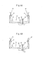
- connection contacts 14 ' there are a total of four in the housing Connection contacts 14 '(see. Fig. 3 and 4A) provided the can contact a total of two pairs.
- Figure 4B shows the construction of a similar, but integrally formed Connection contact 14, the two ends of each has an insulation displacement contact 16 and 16 '. Between these insulation displacement contacts 16 and 16 'are two on the one hand Contact tongues 18 and 18 'and contact bracket 20 and 20' one Contact point provided. The two contact legs will be thereby by a connecting strip or a Connecting loop 19 bridges.
- connection contact 14 ' is shown, which in the essentially corresponds to the connection contact 14 of FIG. 4B.
- the contact point through the contact bracket 20, 20 'of Connection contact 14 ' is formed, but is not Connection or tapping point but a separation point, because the existing at the connection contact 14 Connection strip 19 removed at the connection contact 14 ' is. Characterized is by separating the contact bracket 20, 20 ' Disconnect the connection between the insulation displacement contacts 16 and 16 'of a connection contact 14'.
- connection contact 14 is like this trained that its opposite opposite Insulation displacement contacts 16 and 16 ', the incoming and outgoing contacting each serve a single wire are arranged in a straight line parallel to the Outer walls 22, 24 of the housing 10 extend.
- the Connection contacts 14 are arranged in the housing that two connection contacts 14 each have a smaller one have mutual distance and one each Connection contact pair a larger distance having.
- FIGS. 1 and 2 show, the housing several openings that extend from above into the interior of the housing to open.
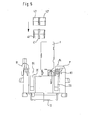
- an incoming or outgoing single wire A in insert an associated insulation displacement contact 16 or 16 ' and contact with the help of an application tool W (Fig. 5), whose tool head is inserted through these openings 30, 30 ' becomes.
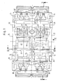
- FIG. 1 shows a 3-pole surge arrester 40, which in the housing opening 34th is inserted.
- the housing openings or the ones below recesses 32 and 34 located have such a size on that from above either the described 3-pole surge arrester 40 or alternatively two 2-pole surge arresters 42 and 42 '(Fig. 5) in the housing can be used.
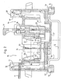
- Fig. 1 to the right of the openings 32 and 34 are further housing openings 38, the insertion of a Isolation plug TR (Fig. 2), a test plug or one Allow fine protection plug F (Fig. 5). These plugs can separate the contact point by the contact bracket 20, 20 'is formed. 2 is the embodiment shown in which a isolating plug TR in the contact point is plugged in.
- Fig. 2 shows how the connection contact 14 '(with separation point) is inserted into the housing 10, 10 '.
- to Contacting of surge arresters 40, 42, 42 ' which can be inserted into the openings 32, 34, serve a total of four contact springs 50, 52, 54 and 56, the with one of the side by side Connection contacts are connected.
- the Contact spring 50 in the tongue 18 of the farthest in Fig. 1 underlying contact 14 'resilient and clamped inserted, whereas the contact spring 52 in the tongue 18 ' of the connection contact lying above in FIG. 1 is plugged in.
- the Contact springs with barbs 58 one Strike the housing edge to prevent it from being pulled out accidentally the contact springs when removing one To prevent surge arresters.
- a flat Contact element 60 For contacting the earth contact 41 (FIGS. 1 and 5) of a 3-pole surge arrester 40 is a flat Contact element 60 is provided, which is best shown in FIG. 3 is recognizable.
- the flat contact element 60 has two juxtaposed, substantially U-shaped openings on, in each case an earth contact 41 (Fig. 5) of a 3-pole surge arrester 40 can be used. in this connection taper the legs of the "U” a little, so this resiliently abut the respective earth contact 41.
- the outer contact springs 50, 52 or 54, 56 To Inserting two surge arresters 40 into openings 32 and 34 (Fig. 1) touch the two outer contacts of the Surge arrester, the outer contact springs 50, 52 or 54, 56.
- the middle earth contact 41 is in the Openings of the contact element 60 added so that a electrically conductive connection between these earth contacts 41 and an earth connection is established. So everyone is on an insulation displacement contact 16, 16 'contacted via a Surge gas arrester chamber connected to earth.
- the contact element 60 is on it Underside with two central spring legs 62, 64, which in turn press resiliently against an earth contact 66, the is held in a snap-in receptacle on the underside of the housing.
- the earth contact 66 is an electrical one conductive connection between the spring contact 60 and the Profile rail 12, which is grounded.
- connection modules are not on a mounting rail or attached to a grounded rail is a (not shown) substantially U-shaped connecting bracket provided, each with one leg from above to two Contact elements 60 from side by side Connection modules can be plugged on. This will make this Contact springs electrically connected and it can established another connection to an earth contact become.
- a 3-pole surge arrester is in one of the openings 32, 34 but two 2-pole surge arresters 42, 42 '(FIG. 5) are used, is alternatively a similar instead of the contact element 60 configured contact element (not shown) used, that has no U-shaped openings, but there is continuously formed. This allows a total of four 2-pole surge arresters 42, 42 'with their Contact surfaces rest on this contact element.
- This Contact element can be hooked 70 in the same way (Fig. 3), as it is the contact element 60 in order to strike against a housing edge and to loosen it prevent.
- connection module To connect several connection modules with each other can if there is no mounting rail or no options are provided to the connection module on a base plate or the like, has the inventive Connection module on its two opposite Outer walls 22 and 24 each have two tapered grooves 26 on that are dovetail-shaped in cross-section are.
- connection module For connecting two side by side Connection module is a separate and complementary profiled connecting web (not shown) provided, which has a double dovetail shape in cross-section and that in the grooves 26 of two side by side Connection modules can be inserted connecting.
- a separate and complementary profiled connecting web not shown
- connection modules hereupon are two adjacent connection modules firmly together coupled and lie with their respective outer walls 22, 24 without spacing.
- connection module On the two remaining outer walls of the connection module two L-shaped wire guide hooks are formed. There are also snap-on options 71 (FIG. 1) for Label holder provided.
- Latching options 13, 13 '(FIG. 2) are provided for a Attachment to a base plate or the like by means of to allow indicated locking lugs.
- the insulation displacement contacts shown in the figures serve a double function.
- these serve as others Possibility of contacting the contact spring 80 Test completion P, through the opening 30 on the Insulation displacement contact can be plugged on (see. Fig. 5).
- the housing 10, 10 ' a free space 84 behind each insulation displacement contact 16.
- the free space 84 is closed at such a distance the opening 38 for the isolating plug arranged that at the same time test termination P and isolating plug TR (Fig. 2) or a fine protection plug F (Fig. 5) can be inserted can.
- the openings 38 for the separation point can be with two caps (not shown) which are not closed can be opened non-destructively. This allows detect unauthorized manipulation at the separation points.
Landscapes
- Engineering & Computer Science (AREA)
- Computer Networks & Wireless Communication (AREA)
- Connections Arranged To Contact A Plurality Of Conductors (AREA)
- Details Of Connecting Devices For Male And Female Coupling (AREA)
- Emergency Protection Circuit Devices (AREA)
Abstract
Description
- Fig. 1
- eine Aufsicht auf ein Anschlussmodul gemäß der Erfindung, wobei ein 3-Pol-Überspannungsgasableiter in das Anschlussmodul eingesetzt ist und die Anschlusskontakte nicht dargestellt sind;
- Fig. 2
- eine Querschnittsansicht durch das Anschlussmodul von Fig. 1 entlang der Linie II-II, wobei zusätzlich eine kontaktierte Ader und ein Trennstecker dargestellt sind;
- Fig. 3
- eine Querschnittsansicht durch das Anschlussmodul von Fig. 1 entlang der Linie III-III, jedoch ohne eingesetzten Überspannungsgasableiter;
- Fig. 4A
- Fig. 4B
- Fig. 5
- einen zum Trennkontakt umgewandelten Anschlusskontakt; einen Anschlusskontakt; und eine Seitenansicht des Anschlussmoduls von Fig. 1 aus der Richtung V, in das von oben ein passiver Prüfabschluss, ein Feinschutzstecker sowie ein Anlegewerkzeug eingeführt sind.
Claims (22)
- Anschlussmodul für die Telekommunikationstechnik, mit einem Gehäuse (10, 10'), und zumindest einem Schneidklemmkontakt (16, 16'), an dem von vorne eine Ader (A) anschließbar ist,
dadurch gekennzeichnet, dass hinter dem Schneidklemmkontakt (16, 16') ein Freiraum (84) ausgebildet ist, in dem ein Prüfabschluss (P) oder dergleichen aufnehmbar ist, der mit dem Schneidklemmkontakt (16, 16') kontaktierbar ist. - Anschlussmodul nach Anspruch 1, dadurch gekennzeichnet, dass das Gehäuse (10, 10') und der Schneidklemmkontakt (16, 16') hinsichtlich des Freiraums (84) derart ausgebildet sind, dass der Prüfabschluss (P) oder dergleichen auch bei geklemmter Ader (A) aufsteckbar ist.
- Anschlussmodul nach Anspruch 1 oder 2, dadurch gekennzeichnet, dass der Prüfabschluss (P) oder dergleichen auch bei eingesetztem Überspannungsgasableiter in den Freiraum (84) einsetzbar ist.
- Anschlussmodul nach zumindest einem der vorangehenden Ansprüche, dadurch gekennzeichnet, dass im Gehäuse eine Öffnung (38) für den Zugang zu einer Trenn- oder Anschlussstelle vorgesehen ist, die sich zwischen zwei gegenüberliegenden Schneidklemmkontakten (16, 16') befindet, wobei die Öffnung (38) vorzugsweise in einem Abstand zu dem Freiraum (84) ausgebildet ist.
- Anschlussmodul nach zumindest einem der vorangehenden Ansprüche, dadurch gekennzeichnet, dass die Öffnung (38) für die Trennstelle mit einer Kappe verschlossen ist, die nicht zerstörungsfrei geöffnet werden kann.
- Anschlussmodul für die Telekommunikationstechnik nach zumindest einem der vorangehenden Ansprüche, mit einem Gehäuse (10, 10'), in dem Anschlusskontakte (14, 14') für ein ankommendes und abgehendes Kontaktieren von mehreren Doppeladern vorgesehen sind,
dadurch gekennzeichnet , dass in dem Gehäuse zumindest eine Ausnehmung (32, 34) vorgesehen ist, die eine solche Größe aufweist, dass von oben entweder ein 3-Pol-Überspannungsgasableiter (40) oder alternativ zwei 2-Pol-Überspannungsgasableiter (42, 42') einsetzbar sind; und dass mittig in der zumindest einen Ausnehmung (32, 34) ein Kontaktelement (60) lösbar an einem Erdkontakt (66) angeordnet ist. - Anschlussmodul nach zumindest einem der vorangehenden Ansprüche, dadurch gekennzeichnet, dass das Kontaktelement (60) flächig ist und zwei nebeneinanderliegende, im wesentlichen U-förmige Öffnungen aufweist, in die jeweils ein 3-Pol-Überspannungsgasableiter (40) mit seinem Erdkontakt (41) einsetzbar ist, um eine leitende Verbindung zwischen den beiden Erdkontakten (41) der nebeneinanderliegenden Überspannungsgasableiter herzustellen, oder dass alternativ ein flächiges Kontaktelement ohne Öffnungen vorgesehen ist, um insgesamt vier 2-Pol-Überspannungsgasableiter (42, 42') zu kontaktieren.
- Anschlussmodul nach zumindest einem der vorangehenden Ansprüche, dass in dem Gehäuse (10, 10') Anschlusskontakte (14, 14') zum Kontaktieren von insgesamt zwei Doppeladern angeordnet sind.
- Anschlussmodul nach zumindest einem der vorangehenden Ansprüche, dadurch gekennzeichnet, dass an einem Anschlusskontakt (14, 14') zwischen zwei Schneidklemmkontakten (16, 16') für eine Ader (A) zwei Kontaktzungen (18, 18') vorgesehen sind, auf die jeweils eine Kontaktfeder (50, 52, 54, 56) zur Kontaktierung eines Überspannungsgasableiters aufsteckbar ist.
- Anschlussmodul nach zumindest einem der vorangehenden Ansprüche, dadurch gekennzeichnet, dass an der Gehäuseunterseite eine Rastaufnahme für eine Erdkontaktfeder (66) vorgesehen ist.
- Anschlussmodul nach zumindest einem der vorangehenden Ansprüche, dadurch gekennzeichnet, dass der Anschlusskontakt (14, 14') zwei Schneidklemmkontakte (16, 16') für jede Einzelader (A) aufweist, die auf einer Geraden angeordnet sind, die parallel zu den beiden Außenwänden (22, 24) verläuft.
- Anschlussmodul nach zumindest einem der vorangehenden Ansprüche, dadurch gekennzeichnet, dass der Abstand zwischen zwei Schneidklemmkontakten einer Doppelader und der Abstand zwischen zwei benachbarten Schneidklemmkontakten zweier Doppeladern eines Moduls unterschiedlich groß ist.
- Anschlussmodul nach zumindest einem der vorangehenden Ansprüche, dadurch gekennzeichnet, dass das Gehäuse (10, 10') an seiner Unterseite eine Rastmöglichkeit (13, 13') für die Befestigung an einer Bodenplatte mittels Rastnasen aufweist.
- Anschlussmodul nach zumindest einem der vorangehenden Ansprüche, dadurch gekennzeichnet, dass das Gehäuse an seiner Unterseite eine Rastmöglichkeit zum Aufrasten auf eine Profilschiene (12) aufweist, und dass das Gehäuse (10, 10') an zwei gegenüberliegenden Außenwänden (22, 24) eine Verbindungseinrichtung (26, 28) aufweist, die ein Ankoppeln eines weiteren Anschlussmodules auch ohne Profilschiene (12) ermöglicht.
- Anschlussmodul nach Anspruch 14, dadurch gekennzeichnet, dass die Verbindungseinrichtung eine sich verjüngende Nut (26) und ein darin eingreifendes Koppelelement (28) aufweist.
- Anschlussmodul nach Anspruch 15, dadurch gekennzeichnet, dass das Koppelelement ein an ein Anschlussmodul angeformter, komplementärer Vorsprung ist, oder vorzugsweise ein separater und profilierter Verbindungssteg (28), der in die Nuten (26) zweier benachbarter Module koppelnd einsetzbar ist.
- Anschlussmodul nach zumindest einem der vorangehenden Ansprüche, dadurch gekennzeichnet, dass in dem Gehäuse (10, 10') eine Kontaktierungsmöglichkeit für eine Schirm- und Erdkontaktierung eines Telekommunikationskabels vorgesehen ist.
- Anschlussmodul nach zumindest einem der vorangehenden Ansprüche, dadurch gekennzeichnet, dass in dem Gehäuse (10, 10') derart beabstandete Öffnungen (30', 38, 32, 34, 30) vorgesehen sind, dass für eine Ader in das Anschlussmodul gleichzeitig von oben ein Trenn- (TR), Prüf-, oder Feinschutzstecker (F) in eine Trennstelle, ein Überspannungsgasableiter (40, 42, 42') in die Ausnehmung und ein Prüfabschluss (P) in den gegenüberliegenden Schneidklemmkontakt (16) einsetzbar sind, und wobei gleichzeitig ein Schneidklemmkontakt (16') beschaltbar ist.
- Anschlussmodul nach zumindest einem der vorangehenden Ansprüche, dadurch gekennzeichnet, dass in dem Gehäuse (10, 10') ein einstückiger Anschlusskontakt (14) für jeweils eine Ader (A) vorgesehen ist, der in der genannten Reihenfolge die folgenden Kontaktierungen ausgebildet hat: einen Schneidklemmkontakt (16'), eine Kontaktstelle mit zwei Kontaktbügeln (20, 20'), zwei Kontakte (18', 18) für Überspannungsgasableiter (40, 42, 42') und einen weiteren Schneidklemmkontakt (16).
- Anschlussmodul nach Anspruch 19, dadurch gekennzeichnet, dass der Anschlusskontakt (14) im Bereich der Kontaktschenkel (20, 20') einen abtrennbaren Verbindungsstreifen (19) aufweist, um die Kontaktstelle zu einem Trennkontakt auszubilden.
- Vorrichtung mit mindestens zwei nebeneinander angeordneten Anschlussmodulen nach zumindest einem der vorstehenden Ansprüche, dadurch gekennzeichnet, dass diese einen im wesentlichen U-förmigen Verbindungsbügel aufweist, der von oben auf die Kontaktelemente (60) zweier benachbarter Anschlussmodule aufsteckbar ist.
- Vorrichtung mit mindestens zwei nebeneinander angeordneten Anschlussmodulen nach einem der vorstehenden Ansprüche, dadurch gekennzeichnet, dass diese mit ihren jeweiligen Außenwänden (22, 24) ohne Abstand aneinander anliegen.
Applications Claiming Priority (3)
| Application Number | Priority Date | Filing Date | Title |
|---|---|---|---|
| DE19608517 | 1996-03-05 | ||
| DE19608517A DE19608517C2 (de) | 1996-03-05 | 1996-03-05 | Anschlußmodul für die Telekommunikationstechnik |
| EP97103429A EP0794590B1 (de) | 1996-03-05 | 1997-03-03 | Anschlussmodul für die Telekommunikationstechnik |
Related Parent Applications (1)
| Application Number | Title | Priority Date | Filing Date |
|---|---|---|---|
| EP97103429A Division EP0794590B1 (de) | 1996-03-05 | 1997-03-03 | Anschlussmodul für die Telekommunikationstechnik |
Publications (3)
| Publication Number | Publication Date |
|---|---|
| EP1246303A2 true EP1246303A2 (de) | 2002-10-02 |
| EP1246303A3 EP1246303A3 (de) | 2003-02-26 |
| EP1246303B1 EP1246303B1 (de) | 2004-12-29 |
Family
ID=7787296
Family Applications (2)
| Application Number | Title | Priority Date | Filing Date |
|---|---|---|---|
| EP97103429A Expired - Lifetime EP0794590B1 (de) | 1996-03-05 | 1997-03-03 | Anschlussmodul für die Telekommunikationstechnik |
| EP02013427A Expired - Lifetime EP1246303B1 (de) | 1996-03-05 | 1997-03-03 | Anschlussmodul für die Telekommunikationstechnik |
Family Applications Before (1)
| Application Number | Title | Priority Date | Filing Date |
|---|---|---|---|
| EP97103429A Expired - Lifetime EP0794590B1 (de) | 1996-03-05 | 1997-03-03 | Anschlussmodul für die Telekommunikationstechnik |
Country Status (3)
| Country | Link |
|---|---|
| EP (2) | EP0794590B1 (de) |
| DE (3) | DE19608517C2 (de) |
| ES (2) | ES2234951T3 (de) |
Cited By (2)
| Publication number | Priority date | Publication date | Assignee | Title |
|---|---|---|---|---|
| EP1921715A3 (de) * | 2006-11-08 | 2008-12-03 | Phoenix Contact GmbH & Co. KG | Reihenklemme, Prüfstecker und Prüfklemmenblock |
| CN106159479A (zh) * | 2015-03-30 | 2016-11-23 | Wago管理有限责任公司 | 接线板 |
Families Citing this family (10)
| Publication number | Priority date | Publication date | Assignee | Title |
|---|---|---|---|---|
| DE29720704U1 (de) | 1997-11-21 | 1998-01-15 | WECO Wester, Ebbinghaus GmbH & Co. KG, 63452 Hanau | Elektrische Anschlußklemme |
| DE29807668U1 (de) * | 1998-04-28 | 1998-07-02 | Quante Ag, 42109 Wuppertal | Anschlußleiste für Kabel mit hohen Übertragungsraten |
| DE10029649C9 (de) | 2000-06-15 | 2008-02-07 | Adc Gmbh | Verteileranschlußmodul für die Telekommunikations- und Datentechnik |
| DE20108245U1 (de) | 2001-05-16 | 2001-07-26 | Schiederwerk MBZ Telekommunikation GmbH & Co., 90451 Nürnberg | Telekommunikation-Endverzweiger mit Prüfabschlüssen |
| DE10232444A1 (de) * | 2002-07-17 | 2004-02-05 | CCS Technology, Inc., Wilmington | Verteilereinrichtung einer Telekommunikationsanlage |
| DE10247871A1 (de) * | 2002-10-14 | 2004-04-22 | Ccs Technology Inc., Wilmington | Verteilereinrichtung einer Telekommunikationsanlage sowie Schutzeinrichtung für eine Verteilereinrichtung |
| DE202008003295U1 (de) * | 2008-03-08 | 2009-07-23 | Weidmüller Interface GmbH & Co. KG | Funktionserweiterbarer Anschlussblock und Modul |
| DE102011016062B4 (de) * | 2011-04-05 | 2018-10-11 | Tyco Electronics Services Gmbh | Verteileranschlussmodul |
| DE102011113333B4 (de) * | 2011-09-15 | 2014-07-03 | Phoenix Contact Gmbh & Co. Kg | Elektrische Reihenklemme und Reihenklemmenblock |
| DE102014103059B4 (de) * | 2014-03-07 | 2024-12-05 | Wago Verwaltungsgesellschaft Mbh | Reihenklemmenanordnung |
Family Cites Families (24)
| Publication number | Priority date | Publication date | Assignee | Title |
|---|---|---|---|---|
| DE2725551C2 (de) * | 1977-06-07 | 1983-11-17 | Krone Gmbh, 1000 Berlin | Elektrischer Klemmverbinder |
| DE2804478C2 (de) * | 1978-01-31 | 1982-11-25 | Krone Gmbh, 1000 Berlin | Elektrischer Klemmverbinder zur löt-, schraub- und abisolierfreien Herstellung eines Kontaktes an einem feststehenden Anschlußelement, insbesondere für die Fernmeldelinientechnik |
| DE7911166U1 (de) * | 1979-04-17 | 1979-07-19 | C. A. Weidmueller Kg, 4930 Detmold | Prüfklemme mit zugeordnetem Trennstecker |
| DE3014796C2 (de) * | 1980-04-17 | 1989-09-21 | Krone Gmbh, 1000 Berlin | Überspannungsableitervorrichtung für Anschlußleisten der Fernmeldetechnik |
| DE3311459C2 (de) * | 1983-03-29 | 1985-03-14 | Siemens AG, 1000 Berlin und 8000 München | Verteilerleiste mit einer Mehrzahl von den abisolierfreien Anschluß elektrischer Leiter gestattenden Doppelanschlußklemmen |
| DE3345803C2 (de) * | 1983-12-17 | 1986-02-13 | Telefonbau Und Normalzeit Gmbh, 6000 Frankfurt | Verteilerleiste für Fernsprechanlagen |
| DE3415369A1 (de) * | 1984-04-25 | 1985-11-07 | Krone Gmbh, 1000 Berlin | Anschlussleiste mit lsa-plus-anschlusselementen zum anschluss von kabeladern und freiluftkabel (dropwire-kabel) |
| DE3710896A1 (de) * | 1987-04-01 | 1988-10-20 | Krone Ag | Verteilerleiste fuer fernmeldekabel, insbesondere hauseingangsverteilerleiste |
| DE3726741C1 (de) * | 1987-08-07 | 1988-09-01 | Krone Ag | Anschlussleiste der Fernmeldetechnik |
| DE3813889C1 (de) * | 1988-04-20 | 1989-04-06 | Krone Ag, 1000 Berlin, De | |
| DE3909783C2 (de) * | 1989-03-22 | 1996-06-13 | Krone Ag | Schutzstecker für Anschlußleisten der Fernmelde- und Datentechnik |
| DE3917270C2 (de) * | 1989-05-23 | 1997-10-23 | Krone Ag | Anschlußleiste mit Überspannungsschutz |
| DE3921227A1 (de) * | 1989-06-28 | 1991-01-10 | Siemens Ag | Verteilereinrichtung fuer telekommunikationsanlagen |
| DE3921203A1 (de) * | 1989-06-28 | 1991-01-10 | Siemens Ag | Schutzstecker fuer eine verteilerleiste in einer telekommunikationsanlage |
| EP0413978A3 (en) * | 1989-08-21 | 1991-07-31 | Siemens Aktiengesellschaft | Protective device for a distributor in a telecommunication installation |
| DE4015238A1 (de) * | 1990-05-10 | 1991-11-14 | Krone Ag | Anschlussleiste fuer die fernmeldetechnik |
| DE4042240C2 (de) * | 1990-12-31 | 1994-12-15 | Quante Ag | Anschlußmodul für eine Verteilereinrichtung, insbesondere für den Hauptverteiler von Fernmeldeeinrichtungen |
| FR2671671A1 (fr) * | 1991-01-10 | 1992-07-17 | Mars Actel | Reglette de raccordement a protections semi-integrees. |
| US5341269A (en) * | 1992-07-31 | 1994-08-23 | Illinois Tool Works Inc. | Voltage protector and grounding bar arrangement for terminal block |
| DE4325952C2 (de) * | 1993-07-27 | 1997-02-13 | Krone Ag | Anschlußleiste für hohe Übertragungsraten in der Telekommunikations- und Datentechnik |
| DE4325614C2 (de) * | 1993-07-30 | 1995-08-31 | Weidmueller Interface | Reihenklemmenanordnung mit Überspannungsschutzorganen |
| FR2708794B1 (fr) * | 1993-08-04 | 1995-09-15 | Pouyet Int | Module d'interconnexion rapide de deux lignes téléphoniques monopaires. |
| DE4333263C2 (de) * | 1993-09-24 | 1995-09-28 | Krone Ag | Reihenklemme |
| DE9407659U1 (de) * | 1994-05-09 | 1994-09-01 | Quante Ag, 42109 Wuppertal | Umschalteadapter für eine Telekommunikationsanschlußleiste |
-
1996
- 1996-03-05 DE DE19608517A patent/DE19608517C2/de not_active Expired - Fee Related
-
1997
- 1997-03-03 ES ES02013427T patent/ES2234951T3/es not_active Expired - Lifetime
- 1997-03-03 EP EP97103429A patent/EP0794590B1/de not_active Expired - Lifetime
- 1997-03-03 ES ES97103429T patent/ES2183995T3/es not_active Expired - Lifetime
- 1997-03-03 DE DE59712151T patent/DE59712151D1/de not_active Expired - Fee Related
- 1997-03-03 EP EP02013427A patent/EP1246303B1/de not_active Expired - Lifetime
- 1997-03-03 DE DE59708851T patent/DE59708851D1/de not_active Expired - Fee Related
Cited By (4)
| Publication number | Priority date | Publication date | Assignee | Title |
|---|---|---|---|---|
| EP1921715A3 (de) * | 2006-11-08 | 2008-12-03 | Phoenix Contact GmbH & Co. KG | Reihenklemme, Prüfstecker und Prüfklemmenblock |
| US7666037B2 (en) | 2006-11-08 | 2010-02-23 | Phoenix Contact Gmbh & Co. Kg | Series terminal, test plug and test terminal block |
| CN106159479A (zh) * | 2015-03-30 | 2016-11-23 | Wago管理有限责任公司 | 接线板 |
| CN106159479B (zh) * | 2015-03-30 | 2019-08-20 | Wago管理有限责任公司 | 接线板 |
Also Published As
| Publication number | Publication date |
|---|---|
| ES2234951T3 (es) | 2005-07-01 |
| DE19608517C1 (de) | 1997-08-14 |
| EP0794590A3 (de) | 1999-12-15 |
| ES2183995T3 (es) | 2003-04-01 |
| DE59712151D1 (de) | 2005-02-03 |
| EP0794590B1 (de) | 2002-12-04 |
| EP1246303B1 (de) | 2004-12-29 |
| DE59708851D1 (de) | 2003-01-16 |
| EP1246303A3 (de) | 2003-02-26 |
| EP0794590A2 (de) | 1997-09-10 |
| DE19608517C2 (de) | 2000-11-09 |
Similar Documents
| Publication | Publication Date | Title |
|---|---|---|
| EP0847106B1 (de) | Anschluss-, Trenn- oder Schaltleiste | |
| EP1022809B1 (de) | Elektrisches Gerät | |
| EP2053696B1 (de) | Reihenklemmenanordnung mit Verbindern | |
| EP0244347B1 (de) | Anschlussleiste für Kabeladern, insbesondere von Fernsprechkabeln | |
| EP0272200B1 (de) | Anschlussleiste für die Fernmeldetechnik | |
| DE19902745B4 (de) | Elektrisches Gerät | |
| EP3075035B1 (de) | Steckverbinderkontaktträger | |
| DE19940971B4 (de) | Elektrische Leiteranschlußklemme mit einer Sammelschiene | |
| EP0794590B1 (de) | Anschlussmodul für die Telekommunikationstechnik | |
| WO2013189616A1 (de) | Verteileranschlussmodul | |
| DE4423339C1 (de) | Verteilereinrichtung, insbesondere für den Hauptverteiler von Fernsprech- und Datenleitungen | |
| EP0477664B1 (de) | Schutzstecker für eine in Telekommunikations-, insbesondere Fernsprechnebenstellenanlagen eingesetzte Verteilerleiste | |
| DE69111568T2 (de) | Schwachstromverbinder für die Vorverdrahtung eines Gebäudes. | |
| EP0739060B1 (de) | Steckverbinder | |
| DE2750540C2 (de) | ||
| DE2712723C2 (de) | Elektrischer Verteiler | |
| DE19721501B4 (de) | Verbinder zur Herstellung einer Querverbindung zwischen ausgerichteten modularen, elektrischen Vorrichtungen | |
| DE4428198C1 (de) | Anschlußleiste für die Telekommunikationstechnik | |
| EP0660458B1 (de) | Anschlusseinheit für Telekommunikations- und Datenleitungen | |
| EP0402658B1 (de) | Anschlussverteilerleiste für ankommende und abgehende elektrische Leitungen | |
| EP0296095B1 (de) | Anschlusseinheit für Kabelpaare der Fernmeldetechnik | |
| DE69403026T2 (de) | Teilnehmeranschlussvorrichtung | |
| DE3641153A1 (de) | Mobile mehrfachschutzkontaktsteckdosenleiste | |
| DE19947087C1 (de) | Kontaktbauteil für einen Verteiler in einer Telekommunikationsanlage | |
| DE10130299A1 (de) | Elektrische Mehrfachsteckdoseneinheit |
Legal Events
| Date | Code | Title | Description |
|---|---|---|---|
| PUAI | Public reference made under article 153(3) epc to a published international application that has entered the european phase |
Free format text: ORIGINAL CODE: 0009012 |
|
| AC | Divisional application: reference to earlier application |
Ref document number: 794590 Country of ref document: EP |
|
| AK | Designated contracting states |
Kind code of ref document: A2 Designated state(s): DE ES FR GB GR IT SE |
|
| PUAL | Search report despatched |
Free format text: ORIGINAL CODE: 0009013 |
|
| AK | Designated contracting states |
Designated state(s): DE ES FR GB GR IT SE Kind code of ref document: A3 Designated state(s): DE ES FR GB GR IT SE |
|
| 17P | Request for examination filed |
Effective date: 20030722 |
|
| AKX | Designation fees paid |
Designated state(s): DE ES FR GB GR IT SE |
|
| GRAP | Despatch of communication of intention to grant a patent |
Free format text: ORIGINAL CODE: EPIDOSNIGR1 |
|
| GRAS | Grant fee paid |
Free format text: ORIGINAL CODE: EPIDOSNIGR3 |
|
| GRAA | (expected) grant |
Free format text: ORIGINAL CODE: 0009210 |
|
| RAP1 | Party data changed (applicant data changed or rights of an application transferred) |
Owner name: QUANTE AKTIENGESELLSCHAFT |
|
| AC | Divisional application: reference to earlier application |
Ref document number: 0794590 Country of ref document: EP Kind code of ref document: P |
|
| AK | Designated contracting states |
Kind code of ref document: B1 Designated state(s): DE ES FR GB GR IT SE |
|
| PG25 | Lapsed in a contracting state [announced via postgrant information from national office to epo] |
Ref country code: IT Free format text: LAPSE BECAUSE OF FAILURE TO SUBMIT A TRANSLATION OF THE DESCRIPTION OR TO PAY THE FEE WITHIN THE PRESCRIBED TIME-LIMIT;WARNING: LAPSES OF ITALIAN PATENTS WITH EFFECTIVE DATE BEFORE 2007 MAY HAVE OCCURRED AT ANY TIME BEFORE 2007. THE CORRECT EFFECTIVE DATE MAY BE DIFFERENT FROM THE ONE RECORDED. Effective date: 20041229 Ref country code: FR Free format text: LAPSE BECAUSE OF FAILURE TO SUBMIT A TRANSLATION OF THE DESCRIPTION OR TO PAY THE FEE WITHIN THE PRESCRIBED TIME-LIMIT Effective date: 20041229 |
|
| REG | Reference to a national code |
Ref country code: GB Ref legal event code: FG4D Free format text: NOT ENGLISH |
|
| REF | Corresponds to: |
Ref document number: 59712151 Country of ref document: DE Date of ref document: 20050203 Kind code of ref document: P |
|
| PG25 | Lapsed in a contracting state [announced via postgrant information from national office to epo] |
Ref country code: GR Free format text: LAPSE BECAUSE OF FAILURE TO SUBMIT A TRANSLATION OF THE DESCRIPTION OR TO PAY THE FEE WITHIN THE PRESCRIBED TIME-LIMIT Effective date: 20050329 Ref country code: SE Free format text: LAPSE BECAUSE OF FAILURE TO SUBMIT A TRANSLATION OF THE DESCRIPTION OR TO PAY THE FEE WITHIN THE PRESCRIBED TIME-LIMIT Effective date: 20050329 |
|
| GBT | Gb: translation of ep patent filed (gb section 77(6)(a)/1977) |
Effective date: 20050413 |
|
| REG | Reference to a national code |
Ref country code: ES Ref legal event code: FG2A Ref document number: 2234951 Country of ref document: ES Kind code of ref document: T3 |
|
| PLBE | No opposition filed within time limit |
Free format text: ORIGINAL CODE: 0009261 |
|
| STAA | Information on the status of an ep patent application or granted ep patent |
Free format text: STATUS: NO OPPOSITION FILED WITHIN TIME LIMIT |
|
| 26N | No opposition filed |
Effective date: 20050930 |
|
| EN | Fr: translation not filed | ||
| PGFP | Annual fee paid to national office [announced via postgrant information from national office to epo] |
Ref country code: ES Payment date: 20060327 Year of fee payment: 10 |
|
| PGFP | Annual fee paid to national office [announced via postgrant information from national office to epo] |
Ref country code: GB Payment date: 20060329 Year of fee payment: 10 |
|
| PGFP | Annual fee paid to national office [announced via postgrant information from national office to epo] |
Ref country code: DE Payment date: 20060502 Year of fee payment: 10 |
|
| GBPC | Gb: european patent ceased through non-payment of renewal fee |
Effective date: 20070303 |
|
| PG25 | Lapsed in a contracting state [announced via postgrant information from national office to epo] |
Ref country code: DE Free format text: LAPSE BECAUSE OF NON-PAYMENT OF DUE FEES Effective date: 20071002 |
|
| PG25 | Lapsed in a contracting state [announced via postgrant information from national office to epo] |
Ref country code: GB Free format text: LAPSE BECAUSE OF NON-PAYMENT OF DUE FEES Effective date: 20070303 |
|
| REG | Reference to a national code |
Ref country code: ES Ref legal event code: FD2A Effective date: 20070305 |
|
| PG25 | Lapsed in a contracting state [announced via postgrant information from national office to epo] |
Ref country code: ES Free format text: LAPSE BECAUSE OF NON-PAYMENT OF DUE FEES Effective date: 20070305 |