EP1246448B1 - Dispositif de traitement d'un substrat sur deux faces - Google Patents
Dispositif de traitement d'un substrat sur deux faces Download PDFInfo
- Publication number
- EP1246448B1 EP1246448B1 EP02252183A EP02252183A EP1246448B1 EP 1246448 B1 EP1246448 B1 EP 1246448B1 EP 02252183 A EP02252183 A EP 02252183A EP 02252183 A EP02252183 A EP 02252183A EP 1246448 B1 EP1246448 B1 EP 1246448B1
- Authority
- EP
- European Patent Office
- Prior art keywords
- flexible substrate
- pathway
- substrate
- reversion
- channel
- Prior art date
- Legal status (The legal status is an assumption and is not a legal conclusion. Google has not performed a legal analysis and makes no representation as to the accuracy of the status listed.)
- Expired - Lifetime
Links
Images




Classifications
-
- H—ELECTRICITY
- H04—ELECTRIC COMMUNICATION TECHNIQUE
- H04N—PICTORIAL COMMUNICATION, e.g. TELEVISION
- H04N1/00—Scanning, transmission or reproduction of documents or the like, e.g. facsimile transmission; Details thereof
- H04N1/00567—Handling of original or reproduction media, e.g. cutting, separating, stacking
- H04N1/0057—Conveying sheets before or after scanning
- H04N1/00572—Conveying sheets before or after scanning with refeeding for double-sided scanning, e.g. using one scanning head for both sides of a sheet
- H04N1/00575—Inverting the sheet prior to refeeding
- H04N1/00578—Inverting the sheet prior to refeeding using at least part of a loop, e.g. using a return loop
-
- B—PERFORMING OPERATIONS; TRANSPORTING
- B65—CONVEYING; PACKING; STORING; HANDLING THIN OR FILAMENTARY MATERIAL
- B65H—HANDLING THIN OR FILAMENTARY MATERIAL, e.g. SHEETS, WEBS, CABLES
- B65H5/00—Feeding articles separated from piles; Feeding articles to machines
- B65H5/22—Feeding articles separated from piles; Feeding articles to machines by air-blast or suction device
- B65H5/228—Feeding articles separated from piles; Feeding articles to machines by air-blast or suction device by air-blast devices
-
- H—ELECTRICITY
- H04—ELECTRIC COMMUNICATION TECHNIQUE
- H04N—PICTORIAL COMMUNICATION, e.g. TELEVISION
- H04N1/00—Scanning, transmission or reproduction of documents or the like, e.g. facsimile transmission; Details thereof
- H04N1/00567—Handling of original or reproduction media, e.g. cutting, separating, stacking
- H04N1/0057—Conveying sheets before or after scanning
- H04N1/00572—Conveying sheets before or after scanning with refeeding for double-sided scanning, e.g. using one scanning head for both sides of a sheet
-
- B—PERFORMING OPERATIONS; TRANSPORTING
- B33—ADDITIVE MANUFACTURING TECHNOLOGY
- B33Y—ADDITIVE MANUFACTURING, i.e. MANUFACTURING OF THREE-DIMENSIONAL [3D] OBJECTS BY ADDITIVE DEPOSITION, ADDITIVE AGGLOMERATION OR ADDITIVE LAYERING, e.g. BY 3D PRINTING, STEREOLITHOGRAPHY OR SELECTIVE LASER SINTERING
- B33Y80/00—Products made by additive manufacturing
-
- B—PERFORMING OPERATIONS; TRANSPORTING
- B65—CONVEYING; PACKING; STORING; HANDLING THIN OR FILAMENTARY MATERIAL
- B65H—HANDLING THIN OR FILAMENTARY MATERIAL, e.g. SHEETS, WEBS, CABLES
- B65H2301/00—Handling processes for sheets or webs
- B65H2301/30—Orientation, displacement, position of the handled material
- B65H2301/33—Modifying, selecting, changing orientation
- B65H2301/333—Inverting
-
- B—PERFORMING OPERATIONS; TRANSPORTING
- B65—CONVEYING; PACKING; STORING; HANDLING THIN OR FILAMENTARY MATERIAL
- B65H—HANDLING THIN OR FILAMENTARY MATERIAL, e.g. SHEETS, WEBS, CABLES
- B65H2406/00—Means using fluid
- B65H2406/10—Means using fluid made only for exhausting gaseous medium
- B65H2406/11—Means using fluid made only for exhausting gaseous medium producing fluidised bed
Definitions
- the present invention relates to a duplexing mechanism in a substrate processing system that includes a mechanism for flexible sheet reversion.
- Inversion requires a duplicate set of sensors in order to accomplish trailing edge alignment.
- US-A-5,923,205 describes an apparatus which uses a series of rollers and deflectors to curl a sheet along its longitudinal axis and then force it over a guide bar which unfolds the sheet with its originally downward-facing surface on top. Essentially, the sheet is twisted about its axis of motion. The sheet is thus subject to forces in several directions which risks tearing of the sheet and potential jams in the reversion apparatus.
- an apparatus for processing a flexible substrate on two sides comprises:
- the system 10 can generally comprise a printing or copying apparatus 12.
- the apparatus 12 can include an input section 14, an output section 16 and a controller 18.
- the input section 14 can comprise for example an image input terminal ("IIT") and the output section 16 can comprise for example an image output terminal ("IOT").
- the apparatus 12 also includes a reversion module 20.
- the reversion module 20 is generally a part of a paper path or object path within the system 10 that runs between the input section 14 and the output section 16. For example, in Fig.
- the reversion module 20 is located in the paper path 21 after the print/copy station 12, and the substrate (not shown) is returned along a paper path 23 in the reverted state to the path 21 and back to the print/copy station 12 for further processing. After processing is complete, the substrate is delivered to the output station 16.
- Fig. 10B shows a comparative example in which the substrate travels along the path 21 through the print/copy station 12, through the reversion module 20 and through a second print/copy station 13 and to the output station 16. In Fig.
- the print/copy station 12 is distributed in space, such as a belt, so that portions of the printing/copy process, such as toner image (latent image) transfer can occur in spatially distinct regions, but the total printing such as fusing images occurs after both images have transferred.
- the reversion module 20 can comprise a mobius reversion module.
- the apparatus 12 can comprise any conventional duplexing printing/copying apparatus, such as for example a duplexing electrophotographic apparatus or a xerographic apparatus and include conventional components. An example of an electrophotographic apparatus can be seen in US-A-6,057,930 .
- the reversion module 20 is generally adapted to revert a substrate, such as for example a sheet of paper, for duplex copying, without changing the leading edge orientation of the paper, as is the case in an inversion module. It is a feature of the present invention to revert the paper as it passes through the module and return the reverted paper along the reversion path using mobius topology for printing on the unimaged side of the sheet. Generally, only a single return path and a single print station are needed in the system 10.
- the reversion module 20 is described herein in conjunction with a print/copy system 12, it should be recognized and understood that the present invention can be incorporated into any system that requires that a substrate be turned over. For example, the present invention could be incorporated into an embossing apparatus or a device in which an adhesive is applied to only one side of the substrate.
- the various machine functions can be regulated by a controller 18.
- the controller 18 is generally a programmable microprocessor that controls all of the machine functions herein described.
- the controller can, for example, provide a comparison count of the copy sheets, the number of documents being recirculated, the number of copy sheets selected by the operator, time delays, jam corrections, etc.
- the control of all of the exemplary systems herein described may be accomplished by conventional control switch inputs from the machine consoles selected by the operator. Conventional sheet path sensors or switches may be utilized to keep track of the position of the documents and the copy sheets.
- the controller 18 regulates the various positions of the gates depending upon the mode of operation selected.
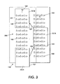
- FIGs. 6A, 6B and 6C Examples of a two-way roller system that can be used in the reversion module incorporating features of the present invention are shown in Figs. 6A, 6B and 6C .
- a two-way roller permits motion in directions at non-perpendicular angles to the roller axle 604 as depicted in Figs 6A-C .
- Fig. 6A a single, two-way nip 602 is presented.
- the nip 602 consists of a set of two discs 612 and 614.
- a set of four perimeter rollers 603 are mounted on or along the perimeter of each disc 612 and 614.
- perimeter rollers 603 are generally constructed so that they are tapered towards the outside so that the outmost profile of the roller 603 is a circle when viewed along the axis.
- a second disc 614 or nip has the same structure but the perimeter rollers 603 are rotated, or positioned, at intervals approximately 45 degrees with respect to the rollers 603 on the first disc 612. The two discs 612, 614 and the relative rotation are needed in order that a perimeter roller 603 is always in contact with the object to be moved.
- These discs 612, 614 share a common axle 604 to form the two-way nip 602.
- a series of two-way nips 602 can share a common axle 604 to form a two-way roller 620. If this two-way roller 620 is in contact with an object, the object can be moved by some external force at an angle that is not perpendicular to the roller axle 604.
- the perimeter rollers 603 rotate permitting this non-perpendicular motion unlike a roller constructed of solid nips without the perimeter rollers 603.
- the two-way roller 620 is capable of exerting a force in the direction perpendicular to the roller axle 604 just like a normal roller because the perimeter rollers 603 can exert a force along their axis of rotation.
- the two-way roller 620 can move an object in a direction perpendicular to axle 604, but permit motion of the object in a different direction.
- Fig. 6C is an example of a two-roller array 640 capable of omni-directional object driving.
- a number of two-way rollers 620 are grouped into perpendicular arrays so that a force in any arbitrary direction within the plane can be exerted on the object by appropriate torque applied to the rollers in the two orthogonal directions.
- the object is free to move in that direction in response to the force because of the two-way roller action described above.
- the arrays 640 are examples of holonomic actuators that can be used with the present invention in that they can provide motion in any direction at any time. As arrays 640 are driven by motors, the flexible sheet can be made to move at any angle with respect to the forward direction at any time.
- An airjet transport system is generally a paper transport system that uses flowing air instead of rollers to apply the motive force to the paper sheets to move the flexible sheet.
- a system controller in the electrophotographic duplicating system interacts with the individual or local module controllers for the various airjets.
- An example of a control architecture for sheet handling is described in US-A-5,999,758 .
- the term "inversion” when the term "inversion" is used herein with regard to a flexible sheet, it is generally meant to mean that the sheet is turned over, i.e. the top surface of the sheet is made the bottom surface and vice versa.
- the leading edge of the sheet of paper prior to inversion is no longer the leading paper edge after inversion, i.e. the two opposite edges of the sheet of paper are reversed.
- the leading edge of the sheet of paper prior to reversion remains the leading edge after reversion.
- the two opposite edges of the sheet of paper are not reversed by the reversion process.
- a significance of the leading edge of the paper staying the same after the reversion process is that it permits the paper handling system to register images with respect to the leading edge rather than the trailing edge as with the inversion process.
- the reversion module 150 comprises an upper channel 140, a curved section 103 and a lower channel 160.
- the upper channel 140 is generally formed between two channel walls or layers, 120 and 125.
- the channel walls can generally comprise the fluid transport system.
- the layers 120 and 125 can include airjets to move a flexible sheet 101 along the channel 140.
- the curved section 103 is approximately a 180° curve from the channel 140 to the channel 160.
- the channel 160 is generally formed between two channel walls or layers, 130 and 135.
- the layers 130 and 135 are similar to the layers 120 and 125.
- a flexible sheet 101 which in this example is shown as a sheet of paper, is caused to enter the upper channel 140, move through the curved section 103 into the lower channel 160 and exit the reversion module.
- the lower channel 160 can be adapted to merge with the upper channel 140, so that the sheet 101 exits the reversion module through the upper channel 140. It is a feature of the present invention to cause a sheet 101 to "revert" as it passes through the reversion module 140 in order to be able to place or form an image for printing or copying on the reverted side or surface of the sheet 101.
- the reversion module 150 can be adapted to allow a sheet 101 to enter the upper channel 140 of the reversion module 150. Generally, then sheet 101 enters the module 150 with an image formed on the side 101A of the sheet 101.
- the sheet 101 can be driven by any suitable fluid transport system along the channel 140, such as for example, an airjet conveyor system 300 comprising airjets 100 in the channel layers or walls 120 and 125.
- an airjet conveyor system 300 comprising airjets 100 in the channel layers or walls 120 and 125.
- the fluid transport layers 120, 125, 130 and 135 are described herein as preferably comprising an air jet transport system, it should be understood that in alternate embodiments, any suitable transport mechanism, fluid transport mechanism or holonomic actuation means can be used to move a sheet 101 through the reversion module.
- the flexible sheet 101 enters into the reversion module 150 through the upper channel 140. Once the sheet 101 is fully within the module 150, the sheet 101 is decelerated to zero velocity, and then transported laterally in the direction of arrow 104 through the 180° curved section 103 of the module and into the lower channel 160. Once the sheet is fully in this lower section 160, the movement of the sheet 101 can again be stopped and motion along the path in the direction of arrow 110 resumes. The "reverted" substrate 101 can then be processed or transported for example, to the transfer station D for duplexing.
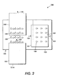
- a section 210 of the module 150 shown in Fig. 4A can connect the upper channel 140 and the lower channel 160.
- the sheet 101 can exit the reversion module 150 on any suitable plane or level compared to the plane or level from which it entered as shown in Fig. 4B .
- Fig. 2 generally requires a deceleration of the sheet 101 in the process direction and therefore large changes in the inter-sheet spacing in the paper path preceding the reversion module 150.
- sheet 101 can be reverted while maintaining the velocity of the sheet 101 in the process direction without any deceleration.
- the need for changes in the paper path velocity and a large intersheet gap can be reduced or eliminated.
- air jets must be constructed and positioned with respect to a flexible object to enable application of on the order of one millinewton of force to each side of the flexible object, with precise force values of the course depending on material and dynamic properties of the flexible object, along with the desired object acceleration and trajectory.
- the exerted air jet forces must be quickly changeable.
- a typical 0.025 centimeter (0.0635 inches) diameter orifice having a length of about 0.1 centimeter (0.254 inches) would be expected to have an intrinsic response time for air movement on the order of 100 microseconds.
- valve response times, controllers, motion analysis, and pressure conditions must also be such that air jet operation and control occurs on a millisecond time scale.
- a paper handling flap valve array system is described is US-A-6,004,395 .
- valves for use in conjunction with the air jet architecture used with the present invention or the architecture of other suitable air jets in accordance with the present invention, is possible with a variety of machining or micromachining techniques, including those associated with conventional integrated circuit fabrication.
- chemical etching, electron beam lithography, photolithography, or other standard integrated circuit batch processing technologies can be used to define necessary air conduits, control or circuitry conduits, holes, orifices, and apertures, and even movable valves.
- injection molding, high precision numerically controlled machines, or stereolithography can be employed for valve construction.
- Materials used in construction may include plastics, metals, or ceramics.
- a semiconductor such as silicon may be coated with single or multiple layers of doped silicon, polysilicon, silicon nitride, silicon, silicon oxide, oxynitride, plastics or aluminum, or any other available material suitable for lithographic processing to define the necessary valve structures or conduits.
- the strength and direction of the directed forces can be greatly modified, allowing, for example, directed tensile or compressive forces to curve objects 101 about a longitudinal axis, a lateral axis, or even curving of selected subregions of an object (e.g. the corner of the object).
- This level of control would, for example, permit impressing curvature on a paper sheet about a longitudinal axis (parallel to the process direction) in order to enhance the paper stiffness.
- the current invention allows for reverting a flexible sheet without changing or switching the leading edge of the sheet rather than inverting the sheet as is done in a duplex printing and copying environment.
- the leading edge 101C of the sheet 101 remains the same. This permits for example, a paper handling system to register images with respect to the leading edge 101C rather than the trailing edge, as is the case with inversion.
- the design of the rest of the paper path becomes much simpler if one only has to align everything with respect to the leading edge. For example, the number of paper edge sensors is roughly halved as well as the number of rollers reduced.
- the present invention allows for reversion at the processing speed even with closely spaced sheets of paper.
- the sheets In order to efficiently use a paper path for example, the sheets should be as close together as possible. With most current inversion methods, the sheet must come to a stop and then its motion reversed. This requires that the sheets be at least one sheet size apart. Therefore the sheets must run at twice the paper path speed in order to separate the sheets for the inversion process.
- One of the features of an embodiment of the present invention is that the paper can be reverted without decelerating the paper. The deceleration process causes the greatest stress on the paper path components, so its elimination greatly improves reliability.
- the sheets can be reverted at the process speed of the machine and they can be spaced at a fraction of the sheet size spacing. This further reduces the cost of duplex printing paper path and allows more sheets to be processed within a set time period.
- fluid flow such as air flow for supporting and moving paper sheets especially for the "reversion" process.
- one print station 502 can be positioned near the input 506 to the reversion module 850 and another print station 504 can be positioned near the output or exit 508.
- the substrate 801 can be processed on one side 801A or surface as it travels through the print station 502, be reverted as travels through the reversion module 850 and be processed on the other side 801B as it is outputted from the reversion module and passes through the print station 504.
- a single print station 704 can be used.
- a reversion module 852 similar in structure and design to the reversion module 850 shown in Fig. 7 , it is transferred back to the print station 704.
- this type of system requires a means, such as channel 854 to recirculate the sheet 801 back to the print station 704.
- This system also requires a splitter 706 to separate sheets that need to be recirculated for duplex imaging from those that need to exit out of the reversion module through output section 710 because both sides, 801A and 801B, of the sheet 801 have been imaged.
- This system also includes a merge point 708, which may also include a splitter, to allow the recirculating sheets to merge back into the same path that a new sheet entering the module 852 from input section 702 would take in the direction of the print station or head 704.
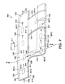
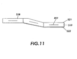
- the substrate 801 travels in the channel 519 of the drive section 520 between the upper surface 521 and the bottom surface 522 of the channel 519.
- the omni-directional drive section or preferably a fluid transport system, is generally adapted to allow movement of the sheet in any desired direction, including forward or backward movement along the paper path as well as lateral movement. This allows the reversion and movement of the substrate 801 back to the original print station 811 in a mobius geometry, or a loop with a single twist.
- the sheet 801 must be decelerated along the line of the paper path in order to reverse course and return to the print station 811. This embodiment provides for reversion and the use of a single print station without any mechanics for splitting or joining paper paths other than the use of fluid drivers.
- the sheet 801 can then be processed out of the reversion module 904 in the direction of arrow 812 through exit or output section 992 for simplex imaging, or if duplex imaging is complete, or processed in the direction of arrow 814 if duplex imaging is desired.
- the sheet 801 is subject to a reversion process.
- surface 801B becomes the face-up surface
- the surface 801A becomes the face-down surface.
- the edge 801C of the sheet 801 continues to be the leading edge of the sheet 801 in the process direction.
- the paper path for a copier using the reversion module 850 has a continuing straight path out of the module towards the second print or imaging station 504.
- the reversion path 524 also acts as the return path. Splitting is accomplished by a sideways or lateral movement of the sheet 801 that moves the sheet into the reversion path 524. Merging is accomplished by having the sheet 801 approach the merge point 528 from a different direction. A cross-sectional view of the merge point 528 shown in Fig. 9 is illustrated in Fig. 11 .
Landscapes
- Engineering & Computer Science (AREA)
- Multimedia (AREA)
- Signal Processing (AREA)
- Mechanical Engineering (AREA)
- Separation, Sorting, Adjustment, Or Bending Of Sheets To Be Conveyed (AREA)
- Supply And Installment Of Electrical Components (AREA)
- Attitude Control For Articles On Conveyors (AREA)
- Container, Conveyance, Adherence, Positioning, Of Wafer (AREA)
- Handling Of Cut Paper (AREA)
- Conveyance By Endless Belt Conveyors (AREA)
- Feeding Of Articles By Means Other Than Belts Or Rollers (AREA)
Claims (8)
- Appareil de traitement d'un substrat flexible (101) sur deux faces comprenant :une voie d'entrée (140) pour recevoir le substrat flexible (101) d'un système de traitement de substrat, le substrat flexible (101) ayant un premier bord comprenant un bord tête dans une direction de traitement (102) et une première face (101A) dans une orientation face au-dessus ;une station de traitement (704) pour traiter la face au-dessus (101A) du substrat flexible ;une voie de retournement adaptée pour recevoir le substrat flexible (101) de la voie d'entrée (140), retourner le substrat flexible en le déplaçant le long de la voie de retournement dans une direction de retournement (104), le premier bord du substrat flexible restant dans la direction de traitement, et ramener le substrat flexible retourné jusqu'à la voie d'entrée, dans laquelle une deuxième face (101B) du substrat flexible (101) est dans l'orientation face au-dessus et le premier bord est le bord tête ; etun point d'intercalation (528) pour intercaler le substrat flexible retourné dans la voie d'entrée (140) pour traiter la face au-dessus (101B) du substrat flexible (101) dans ladite station de traitement (704) ;caractérisé en ce que la voie de retournement comprend :un canal supérieur (140) adapté pour recevoir le substrat flexible avec sa première face (101A) dans une orientation face au-dessus, le canal supérieur (140) étant défini par une première et une deuxième parois planes de canal (120, 125) en opposition l'une à l'autre,une section de canal incurvée (103) comprenant une courbure d'approximativement 180° adaptée pour changer une orientation du substrat flexible, dans laquelle la première face (101A) du substrat flexible est retournée de l'orientation face au-dessus à une orientation face en dessous, la section de canal incurvée (103) étant définie par une première et une deuxième parois de canal incurvées, etun canal inférieur (160) adapté pour recevoir le substrat flexible du canal incurvé (103) et déplacer le substrat dans un canal de sortie vers le point d'intercalation (528), le canal inférieur étant défini par une troisième et une quatrième parois planes de canal (130, 135) en opposition l'une à l'autre, dans lequel le canal supérieur (140), le canal incurvé (103) et le canal inférieur (160) en combinaison forment un canal substantiellement en forme de U défini par des parois de canal en opposition (120, 125, 130, 135).
- Appareil selon la revendication 1 dans lequel la direction de retournement (104) est perpendiculaire à la direction de traitement (102).
- Appareil selon la revendication 1 ou la revendication 2, dans lequel la voie d'entrée (140) et la voie de retournement (160) comprennent une voie en ruban de Möbius à canal unique.
- Appareil selon l'une quelconque des revendications précédentes, dans lequel l'appareil de traitement de substrat est un appareil d'impression adapté pour produire des impressions ou des copies recto verso.
- Appareil selon l'une quelconque des revendications précédentes, comprenant en outre un système de transport fluide adapté pour déplacer le substrat (101) le long de la voie d'entrée (140) et de la voie de retournement (160).
- Appareil selon l'une quelconque des revendications précédentes, comprenant en outre une voie de sortie (710) pour faire sortir un substrat (101) traité, la voie de sortie (710) comprenant un canal continu à partir d'un deuxième point d'intercalation (528) de la voie d'entrée et la voie de retournement, le deuxième point d'intercalation n'incluant pas de diviseur pour diriger le substrat dans la voie de sortie ou la voie de retournement.
- Procédé de retournement d'un substrat flexible (101) dans un appareil de traitement de substrat selon l'une quelconque des revendications 1 à 6, comprenant les étapes de :transporter le substrat flexible (101) dans une première direction (102) le long de la voie d'entrée (140) ;traiter une première surface (101A) du substrat flexible (101) dans la station de traitement (704) ;décélérer le substrat flexible (101) le long de la voie d'entrée (140) ;transporter le substrat flexible (101) dans une deuxième direction (104) le long de la voie de retournement (160) ;retourner le substrat flexible (101) dans la voie de retournement (160) ;décélérer le substrat flexible (101) le long de la voie de retournement (160) ;intercaler le substrat flexible (101) dans la voie d'entrée (140) ; ettraiter une deuxième surface (101B) du substrat flexible (101) dans la station de traitement (704).
- Procédé selon la revendication 7, dans lequel l'étape de retourner le substrat (101) dans la voie de retournement comprend de changer une orientation du substrat (101) dans lequel la première surface (101A) du substrat (101) dans une orientation face au-dessus est retournée dans une orientation face en dessous tandis qu'un premier bord du substrat comprenant un bord tête dans une direction de traitement (102) du substrat (101) reste le bord tête du substrat dans l'orientation retournée.
Applications Claiming Priority (2)
| Application Number | Priority Date | Filing Date | Title |
|---|---|---|---|
| US09/822,688 US6607320B2 (en) | 2001-03-30 | 2001-03-30 | Mobius combination of reversion and return path in a paper transport system |
| US822688 | 2001-03-30 |
Publications (3)
| Publication Number | Publication Date |
|---|---|
| EP1246448A2 EP1246448A2 (fr) | 2002-10-02 |
| EP1246448A3 EP1246448A3 (fr) | 2003-10-22 |
| EP1246448B1 true EP1246448B1 (fr) | 2008-08-27 |
Family
ID=25236696
Family Applications (1)
| Application Number | Title | Priority Date | Filing Date |
|---|---|---|---|
| EP02252183A Expired - Lifetime EP1246448B1 (fr) | 2001-03-30 | 2002-03-26 | Dispositif de traitement d'un substrat sur deux faces |
Country Status (4)
| Country | Link |
|---|---|
| US (1) | US6607320B2 (fr) |
| EP (1) | EP1246448B1 (fr) |
| JP (1) | JP2002332170A (fr) |
| DE (1) | DE60228517D1 (fr) |
Families Citing this family (140)
| Publication number | Priority date | Publication date | Assignee | Title |
|---|---|---|---|---|
| US7226049B2 (en) * | 2003-06-06 | 2007-06-05 | Xerox Corporation | Universal flexible plural printer to plural finisher sheet integration system |
| GB0412647D0 (en) * | 2004-06-07 | 2004-07-07 | Silver Fox Ltd | Register control for printing labels |
| US7396012B2 (en) * | 2004-06-30 | 2008-07-08 | Xerox Corporation | Flexible paper path using multidirectional path modules |
| US7188929B2 (en) * | 2004-08-13 | 2007-03-13 | Xerox Corporation | Parallel printing architecture with containerized image marking engines |
| US7206532B2 (en) * | 2004-08-13 | 2007-04-17 | Xerox Corporation | Multiple object sources controlled and/or selected based on a common sensor |
| US7742185B2 (en) | 2004-08-23 | 2010-06-22 | Xerox Corporation | Print sequence scheduling for reliability |
| US7649645B2 (en) | 2005-06-21 | 2010-01-19 | Xerox Corporation | Method of ordering job queue of marking systems |
| US7787138B2 (en) * | 2005-05-25 | 2010-08-31 | Xerox Corporation | Scheduling system |
| US7619769B2 (en) * | 2005-05-25 | 2009-11-17 | Xerox Corporation | Printing system |
| US7493055B2 (en) * | 2006-03-17 | 2009-02-17 | Xerox Corporation | Fault isolation of visible defects with manual module shutdown options |
| US7136616B2 (en) * | 2004-08-23 | 2006-11-14 | Xerox Corporation | Parallel printing architecture using image marking engine modules |
| US7542059B2 (en) * | 2006-03-17 | 2009-06-02 | Xerox Corporation | Page scheduling for printing architectures |
| US7123873B2 (en) * | 2004-08-23 | 2006-10-17 | Xerox Corporation | Printing system with inverter disposed for media velocity buffering and registration |
| US7245838B2 (en) * | 2005-06-20 | 2007-07-17 | Xerox Corporation | Printing platform |
| US7308218B2 (en) * | 2005-06-14 | 2007-12-11 | Xerox Corporation | Warm-up of multiple integrated marking engines |
| US7224913B2 (en) * | 2005-05-05 | 2007-05-29 | Xerox Corporation | Printing system and scheduling method |
| US8407077B2 (en) * | 2006-02-28 | 2013-03-26 | Palo Alto Research Center Incorporated | System and method for manufacturing system design and shop scheduling using network flow modeling |
| US20070002085A1 (en) * | 2005-06-30 | 2007-01-04 | Xerox Corporation | High availability printing systems |
| US7302199B2 (en) * | 2005-05-25 | 2007-11-27 | Xerox Corporation | Document processing system and methods for reducing stress therein |
| US9250967B2 (en) * | 2004-08-23 | 2016-02-02 | Palo Alto Research Center Incorporated | Model-based planning with multi-capacity resources |
| US7024152B2 (en) * | 2004-08-23 | 2006-04-04 | Xerox Corporation | Printing system with horizontal highway and single pass duplex |
| US7336920B2 (en) * | 2004-09-28 | 2008-02-26 | Xerox Corporation | Printing system |
| US7324779B2 (en) * | 2004-09-28 | 2008-01-29 | Xerox Corporation | Printing system with primary and secondary fusing devices |
| US7751072B2 (en) * | 2004-09-29 | 2010-07-06 | Xerox Corporation | Automated modification of a marking engine in a printing system |
| US7412180B2 (en) * | 2004-11-30 | 2008-08-12 | Xerox Corporation | Glossing system for use in a printing system |
| US7283762B2 (en) | 2004-11-30 | 2007-10-16 | Xerox Corporation | Glossing system for use in a printing architecture |
| US7162172B2 (en) * | 2004-11-30 | 2007-01-09 | Xerox Corporation | Semi-automatic image quality adjustment for multiple marking engine systems |
| US20060114497A1 (en) * | 2004-11-30 | 2006-06-01 | Xerox Corporation | Printing system |
| US7791751B2 (en) * | 2004-11-30 | 2010-09-07 | Palo Alto Research Corporation | Printing systems |
| US7672634B2 (en) * | 2004-11-30 | 2010-03-02 | Xerox Corporation | Addressable fusing for an integrated printing system |
| US7245856B2 (en) * | 2004-11-30 | 2007-07-17 | Xerox Corporation | Systems and methods for reducing image registration errors |
| US7310108B2 (en) * | 2004-11-30 | 2007-12-18 | Xerox Corporation | Printing system |
| US7305194B2 (en) * | 2004-11-30 | 2007-12-04 | Xerox Corporation | Xerographic device streak failure recovery |
| JP4450205B2 (ja) * | 2004-12-24 | 2010-04-14 | ブラザー工業株式会社 | インクジェット記録装置 |
| US7226158B2 (en) * | 2005-02-04 | 2007-06-05 | Xerox Corporation | Printing systems |
| US7873962B2 (en) * | 2005-04-08 | 2011-01-18 | Xerox Corporation | Distributed control systems and methods that selectively activate respective coordinators for respective tasks |
| US8081329B2 (en) | 2005-06-24 | 2011-12-20 | Xerox Corporation | Mixed output print control method and system |
| US7791741B2 (en) * | 2005-04-08 | 2010-09-07 | Palo Alto Research Center Incorporated | On-the-fly state synchronization in a distributed system |
| US8819103B2 (en) * | 2005-04-08 | 2014-08-26 | Palo Alto Research Center, Incorporated | Communication in a distributed system |
| US8014024B2 (en) * | 2005-03-02 | 2011-09-06 | Xerox Corporation | Gray balance for a printing system of multiple marking engines |
| US7697151B2 (en) * | 2005-03-25 | 2010-04-13 | Xerox Corporation | Image quality control method and apparatus for multiple marking engine systems |
| US7258340B2 (en) * | 2005-03-25 | 2007-08-21 | Xerox Corporation | Sheet registration within a media inverter |
| US7416185B2 (en) * | 2005-03-25 | 2008-08-26 | Xerox Corporation | Inverter with return/bypass paper path |
| US7206536B2 (en) * | 2005-03-29 | 2007-04-17 | Xerox Corporation | Printing system with custom marking module and method of printing |
| US7305198B2 (en) * | 2005-03-31 | 2007-12-04 | Xerox Corporation | Printing system |
| US7272334B2 (en) * | 2005-03-31 | 2007-09-18 | Xerox Corporation | Image on paper registration alignment |
| US7245844B2 (en) * | 2005-03-31 | 2007-07-17 | Xerox Corporation | Printing system |
| US7444108B2 (en) * | 2005-03-31 | 2008-10-28 | Xerox Corporation | Parallel printing architecture with parallel horizontal printing modules |
| US7706007B2 (en) * | 2005-04-08 | 2010-04-27 | Palo Alto Research Center Incorporated | Synchronization in a distributed system |
| US7566053B2 (en) * | 2005-04-19 | 2009-07-28 | Xerox Corporation | Media transport system |
| US7593130B2 (en) * | 2005-04-20 | 2009-09-22 | Xerox Corporation | Printing systems |
| US20060244980A1 (en) * | 2005-04-27 | 2006-11-02 | Xerox Corporation | Image quality adjustment method and system |
| US20060268287A1 (en) * | 2005-05-25 | 2006-11-30 | Xerox Corporation | Automated promotion of monochrome jobs for HLC production printers |
| US7486416B2 (en) * | 2005-06-02 | 2009-02-03 | Xerox Corporation | Inter-separation decorrelator |
| US8004729B2 (en) * | 2005-06-07 | 2011-08-23 | Xerox Corporation | Low cost adjustment method for printing systems |
| US7310493B2 (en) * | 2005-06-24 | 2007-12-18 | Xerox Corporation | Multi-unit glossing subsystem for a printing device |
| US7387297B2 (en) * | 2005-06-24 | 2008-06-17 | Xerox Corporation | Printing system sheet feeder using rear and front nudger rolls |
| US7451697B2 (en) * | 2005-06-24 | 2008-11-18 | Xerox Corporation | Printing system |
| US7433627B2 (en) * | 2005-06-28 | 2008-10-07 | Xerox Corporation | Addressable irradiation of images |
| US8259369B2 (en) | 2005-06-30 | 2012-09-04 | Xerox Corporation | Color characterization or calibration targets with noise-dependent patch size or number |
| US8203768B2 (en) * | 2005-06-30 | 2012-06-19 | Xerox Corporaiton | Method and system for processing scanned patches for use in imaging device calibration |
| US7647018B2 (en) * | 2005-07-26 | 2010-01-12 | Xerox Corporation | Printing system |
| US7496412B2 (en) | 2005-07-29 | 2009-02-24 | Xerox Corporation | Control method using dynamic latitude allocation and setpoint modification, system using the control method, and computer readable recording media containing the control method |
| US7466940B2 (en) * | 2005-08-22 | 2008-12-16 | Xerox Corporation | Modular marking architecture for wide media printing platform |
| US7474861B2 (en) * | 2005-08-30 | 2009-01-06 | Xerox Corporation | Consumable selection in a printing system |
| US7911652B2 (en) * | 2005-09-08 | 2011-03-22 | Xerox Corporation | Methods and systems for determining banding compensation parameters in printing systems |
| US7430380B2 (en) * | 2005-09-23 | 2008-09-30 | Xerox Corporation | Printing system |
| US7495799B2 (en) * | 2005-09-23 | 2009-02-24 | Xerox Corporation | Maximum gamut strategy for the printing systems |
| US7444088B2 (en) * | 2005-10-11 | 2008-10-28 | Xerox Corporation | Printing system with balanced consumable usage |
| US7811017B2 (en) * | 2005-10-12 | 2010-10-12 | Xerox Corporation | Media path crossover for printing system |
| US8711435B2 (en) * | 2005-11-04 | 2014-04-29 | Xerox Corporation | Method for correcting integrating cavity effect for calibration and/or characterization targets |
| US7719716B2 (en) * | 2005-11-04 | 2010-05-18 | Xerox Corporation | Scanner characterization for printer calibration |
| US7660460B2 (en) * | 2005-11-15 | 2010-02-09 | Xerox Corporation | Gamut selection in multi-engine systems |
| US7280771B2 (en) * | 2005-11-23 | 2007-10-09 | Xerox Corporation | Media pass through mode for multi-engine system |
| US7519314B2 (en) * | 2005-11-28 | 2009-04-14 | Xerox Corporation | Multiple IOT photoreceptor belt seam synchronization |
| US7636543B2 (en) * | 2005-11-30 | 2009-12-22 | Xerox Corporation | Radial merge module for printing system |
| US7922288B2 (en) * | 2005-11-30 | 2011-04-12 | Xerox Corporation | Printing system |
| US7706737B2 (en) | 2005-11-30 | 2010-04-27 | Xerox Corporation | Mixed output printing system |
| US7575232B2 (en) * | 2005-11-30 | 2009-08-18 | Xerox Corporation | Media path crossover clearance for printing system |
| US7912416B2 (en) * | 2005-12-20 | 2011-03-22 | Xerox Corporation | Printing system architecture with center cross-over and interposer by-pass path |
| US7826090B2 (en) * | 2005-12-21 | 2010-11-02 | Xerox Corporation | Method and apparatus for multiple printer calibration using compromise aim |
| US7756428B2 (en) * | 2005-12-21 | 2010-07-13 | Xerox Corp. | Media path diagnostics with hyper module elements |
| US8102564B2 (en) | 2005-12-22 | 2012-01-24 | Xerox Corporation | Method and system for color correction using both spatial correction and printer calibration techniques |
| US7624981B2 (en) * | 2005-12-23 | 2009-12-01 | Palo Alto Research Center Incorporated | Universal variable pitch interface interconnecting fixed pitch sheet processing machines |
| US7746524B2 (en) * | 2005-12-23 | 2010-06-29 | Xerox Corporation | Bi-directional inverter printing apparatus and method |
| US7963518B2 (en) * | 2006-01-13 | 2011-06-21 | Xerox Corporation | Printing system inverter apparatus and method |
| US8477333B2 (en) * | 2006-01-27 | 2013-07-02 | Xerox Corporation | Printing system and bottleneck obviation through print job sequencing |
| US7630669B2 (en) * | 2006-02-08 | 2009-12-08 | Xerox Corporation | Multi-development system print engine |
| US7672006B2 (en) * | 2006-02-22 | 2010-03-02 | Xerox Corporation | Multi-marking engine printing platform |
| US8194262B2 (en) * | 2006-02-27 | 2012-06-05 | Xerox Corporation | System for masking print defects |
| US7965397B2 (en) * | 2006-04-06 | 2011-06-21 | Xerox Corporation | Systems and methods to measure banding print defects |
| US8330965B2 (en) | 2006-04-13 | 2012-12-11 | Xerox Corporation | Marking engine selection |
| US7681883B2 (en) * | 2006-05-04 | 2010-03-23 | Xerox Corporation | Diverter assembly, printing system and method |
| US7800777B2 (en) * | 2006-05-12 | 2010-09-21 | Xerox Corporation | Automatic image quality control of marking processes |
| US7679631B2 (en) | 2006-05-12 | 2010-03-16 | Xerox Corporation | Toner supply arrangement |
| US7382993B2 (en) * | 2006-05-12 | 2008-06-03 | Xerox Corporation | Process controls methods and apparatuses for improved image consistency |
| US7865125B2 (en) * | 2006-06-23 | 2011-01-04 | Xerox Corporation | Continuous feed printing system |
| US7856191B2 (en) * | 2006-07-06 | 2010-12-21 | Xerox Corporation | Power regulator of multiple integrated marking engines |
| US7924443B2 (en) * | 2006-07-13 | 2011-04-12 | Xerox Corporation | Parallel printing system |
| US8607102B2 (en) * | 2006-09-15 | 2013-12-10 | Palo Alto Research Center Incorporated | Fault management for a printing system |
| US7766327B2 (en) * | 2006-09-27 | 2010-08-03 | Xerox Corporation | Sheet buffering system |
| US7857309B2 (en) * | 2006-10-31 | 2010-12-28 | Xerox Corporation | Shaft driving apparatus |
| US7819401B2 (en) * | 2006-11-09 | 2010-10-26 | Xerox Corporation | Print media rotary transport apparatus and method |
| US7969624B2 (en) * | 2006-12-11 | 2011-06-28 | Xerox Corporation | Method and system for identifying optimal media for calibration and control |
| US8159713B2 (en) * | 2006-12-11 | 2012-04-17 | Xerox Corporation | Data binding in multiple marking engine printing systems |
| US7945346B2 (en) | 2006-12-14 | 2011-05-17 | Palo Alto Research Center Incorporated | Module identification method and system for path connectivity in modular systems |
| US8100523B2 (en) * | 2006-12-19 | 2012-01-24 | Xerox Corporation | Bidirectional media sheet transport apparatus |
| US8145335B2 (en) | 2006-12-19 | 2012-03-27 | Palo Alto Research Center Incorporated | Exception handling |
| US7559549B2 (en) | 2006-12-21 | 2009-07-14 | Xerox Corporation | Media feeder feed rate |
| US8693021B2 (en) * | 2007-01-23 | 2014-04-08 | Xerox Corporation | Preemptive redirection in printing systems |
| US7934825B2 (en) * | 2007-02-20 | 2011-05-03 | Xerox Corporation | Efficient cross-stream printing system |
| US7676191B2 (en) | 2007-03-05 | 2010-03-09 | Xerox Corporation | Method of duplex printing on sheet media |
| EP1970334A3 (fr) * | 2007-03-15 | 2009-12-30 | Heidelberger Druckmaschinen Aktiengesellschaft | Machine de traitement de feuilles dotée d'un dispositif de transport pneumatique |
| US20080260445A1 (en) * | 2007-04-18 | 2008-10-23 | Xerox Corporation | Method of controlling automatic electrostatic media sheet printing |
| US20080268839A1 (en) * | 2007-04-27 | 2008-10-30 | Ayers John I | Reducing a number of registration termination massages in a network for cellular devices |
| US7894107B2 (en) * | 2007-04-27 | 2011-02-22 | Xerox Corporation | Optical scanner with non-redundant overwriting |
| US8253958B2 (en) * | 2007-04-30 | 2012-08-28 | Xerox Corporation | Scheduling system |
| US8169657B2 (en) * | 2007-05-09 | 2012-05-01 | Xerox Corporation | Registration method using sensed image marks and digital realignment |
| US7689311B2 (en) * | 2007-05-29 | 2010-03-30 | Palo Alto Research Center Incorporated | Model-based planning using query-based component executable instructions |
| US7925366B2 (en) * | 2007-05-29 | 2011-04-12 | Xerox Corporation | System and method for real-time system control using precomputed plans |
| US7590464B2 (en) * | 2007-05-29 | 2009-09-15 | Palo Alto Research Center Incorporated | System and method for on-line planning utilizing multiple planning queues |
| US8203750B2 (en) | 2007-08-01 | 2012-06-19 | Xerox Corporation | Color job reprint set-up for a printing system |
| US7697166B2 (en) * | 2007-08-03 | 2010-04-13 | Xerox Corporation | Color job output matching for a printing system |
| US7590501B2 (en) | 2007-08-28 | 2009-09-15 | Xerox Corporation | Scanner calibration robust to lamp warm-up |
| JP4969375B2 (ja) * | 2007-09-07 | 2012-07-04 | デュプロ精工株式会社 | 用紙搬送装置 |
| US20090080955A1 (en) * | 2007-09-26 | 2009-03-26 | Xerox Corporation | Content-changing document and method of producing same |
| US7831164B2 (en) * | 2008-03-21 | 2010-11-09 | Xerox Corporation | Fuser with gloss feedback control |
| US8693012B2 (en) | 2008-09-04 | 2014-04-08 | Xerox Corporation | Run cost optimization for multi-engine printing system |
| US8045218B2 (en) * | 2008-10-15 | 2011-10-25 | Xerox Corporation | Digital compensation method and apparatus using image-to-image distortion map relating reference mark grids |
| US8204416B2 (en) * | 2008-12-02 | 2012-06-19 | Xerox Corporation | Method and apparatus for measuring color-to-color registration |
| US7976012B2 (en) | 2009-04-28 | 2011-07-12 | Xerox Corporation | Paper feeder for modular printers |
| US8155547B2 (en) * | 2009-06-26 | 2012-04-10 | Xerox Corporation | Apparatuses useful for printing and corresponding methods |
| US8441680B2 (en) * | 2009-07-22 | 2013-05-14 | Xerox Corporation | Black point compensation in a TIPP architecture |
| JP5556095B2 (ja) * | 2009-09-10 | 2014-07-23 | 富士ゼロックス株式会社 | 反転装置および画像形成装置 |
| JP5742371B2 (ja) | 2011-03-29 | 2015-07-01 | 富士ゼロックス株式会社 | 反転搬送装置、画像形成装置および搬送装置 |
| JP5799573B2 (ja) * | 2011-05-12 | 2015-10-28 | 富士ゼロックス株式会社 | 画像形成装置および記録材処理装置 |
| JP2013023330A (ja) * | 2011-07-20 | 2013-02-04 | Fuji Xerox Co Ltd | 画像形成装置およびシート搬送装置 |
| JP5737227B2 (ja) * | 2012-06-04 | 2015-06-17 | コニカミノルタ株式会社 | 画像形成装置 |
| US9010924B2 (en) | 2012-07-11 | 2015-04-21 | Xerox Corporation | System and method for aligning duplex images using alignment marks |
| US8944431B1 (en) * | 2013-07-22 | 2015-02-03 | Eastman Kodak Company | Compact inverter for cut sheet media |
Family Cites Families (8)
| Publication number | Priority date | Publication date | Assignee | Title |
|---|---|---|---|---|
| US4365794A (en) * | 1980-10-02 | 1982-12-28 | Xerox Corporation | Toggle arm inverter |
| JPS60102360A (ja) * | 1983-11-07 | 1985-06-06 | Fuji Xerox Co Ltd | 紙送り機構 |
| DE3503368A1 (de) * | 1985-02-01 | 1986-08-07 | Heidelberger Druckmaschinen Ag, 6900 Heidelberg | Bogenwender fuer kleinoffsetmaschinen |
| US5293205A (en) * | 1992-01-13 | 1994-03-08 | Delphax Systems | Side to side sheet inverter |
| US5691921A (en) * | 1996-01-05 | 1997-11-25 | Xerox Corporation | Thermal sensors arrays useful for motion tracking by thermal gradient detection |
| US5634636A (en) * | 1996-01-11 | 1997-06-03 | Xerox Corporation | Flexible object handling system using feedback controlled air jets |
| US6195151B1 (en) * | 1999-09-28 | 2001-02-27 | Hewlett-Packard Company | Media handling system for duplex printing |
| ATE308477T1 (de) * | 2000-05-18 | 2005-11-15 | Eastman Kodak Co | Wendeeinrichtung |
-
2001
- 2001-03-30 US US09/822,688 patent/US6607320B2/en not_active Expired - Lifetime
-
2002
- 2002-03-26 DE DE60228517T patent/DE60228517D1/de not_active Expired - Lifetime
- 2002-03-26 EP EP02252183A patent/EP1246448B1/fr not_active Expired - Lifetime
- 2002-03-29 JP JP2002093712A patent/JP2002332170A/ja active Pending
Also Published As
| Publication number | Publication date |
|---|---|
| US6607320B2 (en) | 2003-08-19 |
| EP1246448A2 (fr) | 2002-10-02 |
| US20020141805A1 (en) | 2002-10-03 |
| EP1246448A3 (fr) | 2003-10-22 |
| DE60228517D1 (de) | 2008-10-09 |
| JP2002332170A (ja) | 2002-11-22 |
Similar Documents
| Publication | Publication Date | Title |
|---|---|---|
| EP1246448B1 (fr) | Dispositif de traitement d'un substrat sur deux faces | |
| EP1246449B1 (fr) | Dispositif de renversement d'une feuille souple | |
| US5634636A (en) | Flexible object handling system using feedback controlled air jets | |
| US5897097A (en) | Passively addressable fluid valves having S-shaped blocking films | |
| US7510182B2 (en) | Flexible paper path method using multidirectional path modules | |
| EP0828101B1 (fr) | Valves adressables de façon passive | |
| US6089534A (en) | Fast variable flow microelectromechanical valves | |
| US6120002A (en) | Fluid valves having cantilevered blocking films | |
| US7421241B2 (en) | Printing system with inverter disposed for media velocity buffering and registration | |
| US5008713A (en) | Sheet conveying apparatus and sheet conveying method | |
| US6039316A (en) | Multi-hierarchical control system for controlling object motion with smart matter | |
| JP3923625B2 (ja) | フレキシブルオブジェクトを移動させるための搬送システム及び流体ジェットアレイ支持システム | |
| US6397023B1 (en) | Techniques for achieving correct order in printer output | |
| US5999758A (en) | Hybrid hierarchical control architecture for media handling | |
| EP1213624B1 (fr) | Système pour retourner des feuilles | |
| EP0960845A1 (fr) | Chemin d'alimentation de papier pneumatique | |
| US7566055B2 (en) | Substrate inverter systems and methods | |
| US8459644B1 (en) | Device and method for high-speed media inversion using a dual path, single reversing roll inverter | |
| JPS6082569A (ja) | 複写機等のソ−タ | |
| JPH054777A (ja) | シート搬送装置 | |
| JP2001031294A (ja) | 斜行シート矯正装置とこの装置を備えた画像形成装置 |
Legal Events
| Date | Code | Title | Description |
|---|---|---|---|
| PUAI | Public reference made under article 153(3) epc to a published international application that has entered the european phase |
Free format text: ORIGINAL CODE: 0009012 |
|
| AK | Designated contracting states |
Kind code of ref document: A2 Designated state(s): AT BE CH CY DE DK ES FI FR GB GR IE IT LI LU MC NL PT SE TR |
|
| AX | Request for extension of the european patent |
Free format text: AL;LT;LV;MK;RO;SI |
|
| PUAL | Search report despatched |
Free format text: ORIGINAL CODE: 0009013 |
|
| AK | Designated contracting states |
Kind code of ref document: A3 Designated state(s): AT BE CH CY DE DK ES FI FR GB GR IE IT LI LU MC NL PT SE TR |
|
| AX | Request for extension of the european patent |
Extension state: AL LT LV MK RO SI |
|
| RIC1 | Information provided on ipc code assigned before grant |
Ipc: 7B 65H 15/00 B Ipc: 7H 04N 1/00 A |
|
| 17P | Request for examination filed |
Effective date: 20040422 |
|
| AKX | Designation fees paid |
Designated state(s): DE FR GB |
|
| 17Q | First examination report despatched |
Effective date: 20041008 |
|
| 17Q | First examination report despatched |
Effective date: 20041008 |
|
| GRAP | Despatch of communication of intention to grant a patent |
Free format text: ORIGINAL CODE: EPIDOSNIGR1 |
|
| GRAS | Grant fee paid |
Free format text: ORIGINAL CODE: EPIDOSNIGR3 |
|
| GRAA | (expected) grant |
Free format text: ORIGINAL CODE: 0009210 |
|
| AK | Designated contracting states |
Kind code of ref document: B1 Designated state(s): DE FR GB |
|
| REG | Reference to a national code |
Ref country code: GB Ref legal event code: FG4D |
|
| REF | Corresponds to: |
Ref document number: 60228517 Country of ref document: DE Date of ref document: 20081009 Kind code of ref document: P |
|
| PLBE | No opposition filed within time limit |
Free format text: ORIGINAL CODE: 0009261 |
|
| STAA | Information on the status of an ep patent application or granted ep patent |
Free format text: STATUS: NO OPPOSITION FILED WITHIN TIME LIMIT |
|
| 26N | No opposition filed |
Effective date: 20090528 |
|
| PGFP | Annual fee paid to national office [announced via postgrant information from national office to epo] |
Ref country code: FR Payment date: 20140328 Year of fee payment: 13 |
|
| PGFP | Annual fee paid to national office [announced via postgrant information from national office to epo] |
Ref country code: DE Payment date: 20150219 Year of fee payment: 14 |
|
| PGFP | Annual fee paid to national office [announced via postgrant information from national office to epo] |
Ref country code: GB Payment date: 20150226 Year of fee payment: 14 |
|
| REG | Reference to a national code |
Ref country code: FR Ref legal event code: ST Effective date: 20151130 |
|
| PG25 | Lapsed in a contracting state [announced via postgrant information from national office to epo] |
Ref country code: FR Free format text: LAPSE BECAUSE OF NON-PAYMENT OF DUE FEES Effective date: 20150331 |
|
| REG | Reference to a national code |
Ref country code: DE Ref legal event code: R119 Ref document number: 60228517 Country of ref document: DE |
|
| GBPC | Gb: european patent ceased through non-payment of renewal fee |
Effective date: 20160326 |
|
| PG25 | Lapsed in a contracting state [announced via postgrant information from national office to epo] |
Ref country code: DE Free format text: LAPSE BECAUSE OF NON-PAYMENT OF DUE FEES Effective date: 20161001 Ref country code: GB Free format text: LAPSE BECAUSE OF NON-PAYMENT OF DUE FEES Effective date: 20160326 |