EP1246571B1 - Chirurgisches instrument - Google Patents
Chirurgisches instrument Download PDFInfo
- Publication number
- EP1246571B1 EP1246571B1 EP00990823A EP00990823A EP1246571B1 EP 1246571 B1 EP1246571 B1 EP 1246571B1 EP 00990823 A EP00990823 A EP 00990823A EP 00990823 A EP00990823 A EP 00990823A EP 1246571 B1 EP1246571 B1 EP 1246571B1
- Authority
- EP
- European Patent Office
- Prior art keywords
- surgical instrument
- opening
- grip element
- shank
- wound
- Prior art date
- Legal status (The legal status is an assumption and is not a legal conclusion. Google has not performed a legal analysis and makes no representation as to the accuracy of the status listed.)
- Expired - Lifetime
Links
- 208000027418 Wounds and injury Diseases 0.000 claims abstract description 17
- 210000000988 bone and bone Anatomy 0.000 claims abstract description 17
- 206010010149 Complicated fracture Diseases 0.000 claims abstract description 4
- 239000003814 drug Substances 0.000 claims abstract 2
- 230000000717 retained effect Effects 0.000 claims 1
- 238000010276 construction Methods 0.000 abstract 1
- 238000010079 rubber tapping Methods 0.000 description 2
- 238000001356 surgical procedure Methods 0.000 description 1
Images

Classifications
-
- A—HUMAN NECESSITIES
- A61—MEDICAL OR VETERINARY SCIENCE; HYGIENE
- A61B—DIAGNOSIS; SURGERY; IDENTIFICATION
- A61B17/00—Surgical instruments, devices or methods
- A61B17/02—Surgical instruments, devices or methods for holding wounds open, e.g. retractors; Tractors
-
- A—HUMAN NECESSITIES
- A61—MEDICAL OR VETERINARY SCIENCE; HYGIENE
- A61B—DIAGNOSIS; SURGERY; IDENTIFICATION
- A61B17/00—Surgical instruments, devices or methods
- A61B17/02—Surgical instruments, devices or methods for holding wounds open, e.g. retractors; Tractors
- A61B17/025—Joint distractors
Definitions
- the invention relates to a surgical instrument that as Wound and bone hook is formed and in the Medical technology especially for surgical work at complicated fractures can be used.
- wound and bone hooks which are designed as single-hook hooks
- surgical practice it is often necessary to use a large number of different instruments for pulling, prying, and tapping, whereby an instrument change for a surgeon, depending on the respective operating situations and operating conditions of the different instruments, is very time-consuming and energy-intensive, since it is absolutely necessary can be to operate a used surgical instrument with a different hand position than intended.
- a surgeon has to adjust to a wide variety of ergonomically designed instruments through operations-related handling, which also requires high skills combined with effort.
- the invention is therefore based on the object of a wound Train the bone hook so that it is for A wide variety of surgical tasks can be used universally is.
- the surgical instrument have the features of claim 1, in particular that the opening in the shaft of the instrument is designed as a tapered bore.
- the instrument is formed in two parts, in that the shaft has an opening into which a grip element can be inserted so that it cannot be lost, by means of which the surgical instrument designed as a wound and bone hook can be handled differently when in use.
- the two-part embodiment of the wound and bone hook is not tied to a special shape and dimensions, but can generally be transferred to all hook shapes, so that even the single-hook hooks, which have been tried and tested for decades, can be retrofitted with little effort by incorporating an opening in the shaft area.
- the wound and bone hooks can be converted into a stable, handy tool in a very short time during an operation by inserting the grip element, which can work as a tapping, pulling or turning tool of a surgeon with complicated fractures.
- this opening is centered and transverse to the Longitudinal direction in the shaft of the surgical instrument is arranged.
- the grip element is designed as a bolt is.
- the grip element by means of a ball catch, consisting of a ball with a spring, trained Holding element is held.
- the ball snaps onto the side surface of the shaft of the surgical instrument. By pushing in the ball can disengage the holding element and the grip element in the easiest way to remove them.
- An advantageous embodiment is also that the circumference of the handle element, that is, the outer Lateral surface, wells at the same distance from each other has, for better handling of the wound and Bone hook during surgery.
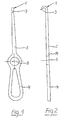
- FIGS. 1 and 2 shows a wound and bone hook 1 according to the prior art, which consists of an approximately rectilinear shaft 2, the head part of which is designed as a hook 3 and the other end of which is designed as a handle 4.
- a circular opening 5 for fastening a grip element 6 transversely to the longitudinal axis of the shaft 2 of the wound and bone hook 1 is preferably arranged in the boundary region between the hook 3 and the handle 4, essentially approximately in the middle of the shaft 2.
- the grip element 6 is preferably bolt-shaped.
- the cross section of the grip element 6 is over its entire Body length essentially the same; however, are preferred its circumference, that is, in its lateral surface, depressions 9 provided that are substantially evenly spaced are arranged to each other. These wells are used for better handling of the grip element 6, for example during an operation.
- Figure 3 is on the handle element 6 conical approach 10 provided in the corresponding conical design of the Opening 5 of the wound and bone hook 1 can be used.
- Handle element 6 in the inserted position takes place by means of a holding element which consists of a ball 11 and a spring 12, which is in a in the handle 6th provided transverse bore 13 are arranged.
- a holding element which consists of a ball 11 and a spring 12, which is in a in the handle 6th provided transverse bore 13 are arranged.
Landscapes
- Health & Medical Sciences (AREA)
- Life Sciences & Earth Sciences (AREA)
- Surgery (AREA)
- Heart & Thoracic Surgery (AREA)
- Engineering & Computer Science (AREA)
- Biomedical Technology (AREA)
- Nuclear Medicine, Radiotherapy & Molecular Imaging (AREA)
- Medical Informatics (AREA)
- Molecular Biology (AREA)
- Animal Behavior & Ethology (AREA)
- General Health & Medical Sciences (AREA)
- Public Health (AREA)
- Veterinary Medicine (AREA)
- Surgical Instruments (AREA)
- Agricultural Chemicals And Associated Chemicals (AREA)
Description
In der Operationspraxis ist es aber vielfach erforderlich, eine große Anzahl unterschiedlicher Instrumente zum Ziehen, Hebeln und Klopfen zu verwenden, wobei ein Instrumentenwechsel für einen Chirurgen abhängig von den jeweiligen Operationssituationen und Einsatzbedingungen der unterschiedlichen Instrumente sehr zeit- und kraftaufwendig ist, da es durchaus erforderlich sein kann, ein verwendetes chirurgisches Instrument mit einer anderen Handstellung zu bedienen, als dafür vorgesehen. Außerdem muss sich ein Chirurg durch operationsbedingte Handhabungen auf unterschiedlichste ergonomisch gestaltete Instrumente einstellen, was ebenfalls hohe Fertigkeiten verbunden mit Kraftaufwand erfordert.
Die zweiteilige Ausführungsform des Wund- und Knochenhakens ist dabei nicht an eine spezielle Form und Abmaße gebunden, sondern allgemein auf alle Hakenformen übertragbar, so dass auch die beispielsweise seit Jahrzehnten bewährten Einzinkerhaken durch Einarbeiten einer Öffnung im Schaftbereich ohne großen Aufwand nachgerüstet werden können.
Durch die zweiteilige Ausführung des Wund- und Knochenhakens kann außerdem während einer Operation durch Einsetzen des Griffelementes der Wund- und Knochenhaken mit nur einem Handgriff in kürzester Zeit in ein stabiles, handliches Werkzeug umgerüstet werden, das als Klopf-, Zieh- oder Drehwerkzeug die Arbeit eines Chirurgen bei komplizierten Frakturen erleichtert.
- Fig. 1
- einen Wund- und Knochenhaken in Vorderansicht;
- Fig. 2
- diesen Wund- und Knochenhaken in Seitenansicht;
- Fig. 3
- eine Darstellung eines Griffelementes und
- Fig.4
- eine Einzelheit eines Halteelementes.
Vorzugsweise im Grenzbereich zwischen dem Haken 3 und dem Handgriff 4, im wesentlichen in etwa der Mitte des Schaftes 2, ist eine kreisrunde Öffnung 5 zur Befestigung eines Griffelementes 6 quer zur Längsachse des Schaftes 2 des Wund- und Knochenhakens 1 angeordnet.
Das Griffelement 6 ist entsprechend der Figur 3 vorzugsweise bolzenförmig ausgebildet.
Claims (5)
- Chirurgisches Instrument (1), das als Wund- und Knochenhaken (1) ausgeführt ist und im Bereich der Medizintechnik für chirurgische Arbeiten insbesondere bei komplizierten Frakturen einsetzbar ist, umfassend einen Schaft (2) mit einem hakenförmig (3) ausgebildeten Kopfteil und einem Endteil in Form eines Handgriffes (4), wobei im Schaft (2) des zweiteiligen chirurgischen Instrumentes (1) eine Öffnung (5) vorgesehen ist, zur Aufnahme eines Griffelementes (6),
wobei die Öffnung (5) mittig und quer zu seiner Längsrichtung im Schaft (2) des chirurgischen Instrumentes (1) angeordnet ist und in die Öffnung (5) ein Griffelement (6) unverlierbar einsetzbar ist,
dadurch gekennzeichnet, dass
die Öffnung (5) im Schaft (2) des chirurgischen Instrumentes (1) als Kegelbohrung ausgebildet ist. - Chirurgisches Instrument nach Anspruche 1,
dadurch gekennzeichnet, dass
das Griffelement (6) bolzenförmig ausgebildet ist. - Chirurgisches Instrument nach Anspruch 2,
dadurch gekennzeichnet, dass
das Griffelement (6) in die Öffnung (5) im Schaft (2) des chirurgischen Instrumentes (1) mittels eines kegelförmigen Ansatzes (10) einsteckbar ist. - Chirurgisches Instrument nach Anspruch 2,
dadurch gekennzeichnet, dass
das Griffelement (6) mittels eines als Kugelrast (11, 12, 13) ausgebildeten Halteelementes an der Seitenfläche (14) des Schaftes (2) des chirurgischen Instrumentes (1) gehalten ist. - Chirurgisches Instrument nach einem der Ansprüche 1 bis 4,
dadurch gekennzeichnet, dass
der Umfang des Griffelementes (6) in gleichem Abstand zueinander angeordnete Vertiefungen (9) aufweist.
Applications Claiming Priority (3)
| Application Number | Priority Date | Filing Date | Title |
|---|---|---|---|
| DE19963456 | 1999-12-28 | ||
| DE19963456A DE19963456A1 (de) | 1999-12-28 | 1999-12-28 | Chirurgisches Instrument |
| PCT/EP2000/013275 WO2001047423A1 (de) | 1999-12-28 | 2000-12-27 | Chirurgisches instrument |
Publications (2)
| Publication Number | Publication Date |
|---|---|
| EP1246571A1 EP1246571A1 (de) | 2002-10-09 |
| EP1246571B1 true EP1246571B1 (de) | 2003-09-17 |
Family
ID=7934797
Family Applications (1)
| Application Number | Title | Priority Date | Filing Date |
|---|---|---|---|
| EP00990823A Expired - Lifetime EP1246571B1 (de) | 1999-12-28 | 2000-12-27 | Chirurgisches instrument |
Country Status (5)
| Country | Link |
|---|---|
| EP (1) | EP1246571B1 (de) |
| AT (1) | ATE249786T1 (de) |
| AU (1) | AU3016801A (de) |
| DE (2) | DE19963456A1 (de) |
| WO (1) | WO2001047423A1 (de) |
Families Citing this family (4)
| Publication number | Priority date | Publication date | Assignee | Title |
|---|---|---|---|---|
| DE102004047937B4 (de) * | 2004-10-01 | 2006-08-10 | Quaden, René | Handgriff zur Verwendung an einem Werkzeug oder Instrument |
| DE102006000739A1 (de) * | 2006-01-04 | 2007-07-12 | Interlock Medizintechnik Gmbh | Handgriff zur Verwendung an einem Werkzeug oder Instrument |
| DE102006016212B4 (de) * | 2006-04-03 | 2019-07-04 | Aesculap Ag | Chirurgische Retraktorverlängerung und chirurgischer Retraktorsatz |
| CN110123494B (zh) * | 2019-05-30 | 2023-07-18 | 青岛大学附属医院 | 人工髋关节置换术中股骨假体复位装置 |
Family Cites Families (10)
| Publication number | Priority date | Publication date | Assignee | Title |
|---|---|---|---|---|
| US1708578A (en) * | 1927-05-07 | 1929-04-09 | Hyde Tamble Fredrick | Surgical instrument |
| US3857386A (en) * | 1973-08-17 | 1974-12-31 | T Ashbell | Surgical device for holding and retracting skin or bone |
| DE7439126U (de) * | 1974-11-23 | 1975-05-15 | Holzhauer + Sutter Medizinisch Tech | Handgriff für Wundhaken, Knochenhebel od. dgl. |
| JPS6235454Y2 (de) * | 1978-08-17 | 1987-09-09 | ||
| US4934352A (en) * | 1982-10-22 | 1990-06-19 | Sullivan Jr Eugene M | Surgical retractor handle construction |
| US4632111A (en) * | 1985-03-21 | 1986-12-30 | Minnesota Mining And Manufacturing Company | Acetabular cup positioning apparatus |
| US4995875A (en) * | 1988-05-27 | 1991-02-26 | Cecil Coes | Femoral elevating tool |
| US5217463A (en) * | 1990-04-11 | 1993-06-08 | Mikhail W F Michael | Method for performing knee surgery and retractors for use therein |
| US5222951A (en) * | 1992-04-13 | 1993-06-29 | Leonard Bloom | Guarded skin hook for surgical use |
| US5558621A (en) * | 1995-04-24 | 1996-09-24 | Heil Associates Inc. | Surgical retractor with cross bar grips |
-
1999
- 1999-12-28 DE DE19963456A patent/DE19963456A1/de not_active Withdrawn
-
2000
- 2000-12-27 AT AT00990823T patent/ATE249786T1/de not_active IP Right Cessation
- 2000-12-27 WO PCT/EP2000/013275 patent/WO2001047423A1/de not_active Ceased
- 2000-12-27 DE DE50003773T patent/DE50003773D1/de not_active Expired - Fee Related
- 2000-12-27 AU AU30168/01A patent/AU3016801A/en not_active Abandoned
- 2000-12-27 EP EP00990823A patent/EP1246571B1/de not_active Expired - Lifetime
Also Published As
| Publication number | Publication date |
|---|---|
| AU3016801A (en) | 2001-07-09 |
| DE19963456A1 (de) | 2001-11-08 |
| WO2001047423A1 (de) | 2001-07-05 |
| EP1246571A1 (de) | 2002-10-09 |
| DE50003773D1 (de) | 2003-10-23 |
| ATE249786T1 (de) | 2003-10-15 |
Similar Documents
| Publication | Publication Date | Title |
|---|---|---|
| EP0011258B1 (de) | Vorrichtung zur äusseren Festlegung der Teile eines gebrochenen Knochens | |
| DE3212828C2 (de) | Chirurgische Klammer und Vorrichtung zum Entfernen von chirurgischen Klammern | |
| DE9210327U1 (de) | Zangengriff für medizinische Gerätschaften | |
| EP0736286A2 (de) | Osteosynthese-Hilfsmittel zur Versorgung subtrochanterer, pertrochanterer und Schenkelhalsfrakturen | |
| DE3941523A1 (de) | Chirurgisches gleitinstrument und verfahren zur handhabung desselben | |
| DE102015008036A1 (de) | Pedikelschraube mit Tulpe | |
| EP0613657A1 (de) | Befestigungsnagel und Setzwerkzeug hierfür | |
| DE202004004844U1 (de) | Schraubendreher für Knochenschrauben | |
| DE3916198A1 (de) | Verankerungselement | |
| EP1682015B1 (de) | Zeckenzieher | |
| DE19625416A1 (de) | Anordnung aus einem Schraubendreher und einer entsprechenden Schraube | |
| EP1246571B1 (de) | Chirurgisches instrument | |
| CH634742A5 (en) | Device for fixing bone fragments | |
| EP0714334A1 (de) | Spannfutter und zugehöriges werkzeug | |
| EP0335285B1 (de) | Steckverbindung zur Befestigung von Zahn- oder Kiefersegmenten auf einer Modellbasis | |
| DE19732983B4 (de) | Instrument zur Knochenaufweitung | |
| EP0498518A1 (de) | Gelenkprothesensystem | |
| DE9310668U1 (de) | Schraubendreher | |
| DE102010060322A1 (de) | Chirurgisches Instrument | |
| AT376119B (de) | Markdraht und werkzeug zum einsetzen und ausziehen solcher markdraehte | |
| DE102005011917A1 (de) | Dentalinstrument | |
| WO2003053265A1 (de) | Modularer knochennagel | |
| DE29703857U1 (de) | Chirurgisches Instrument | |
| DE202013105409U1 (de) | Schraube insbesondere Knochenschraube und ein Werkzeug hierfür | |
| EP0314902B1 (de) | Einschlaginstrument für chirurgische Klingen |
Legal Events
| Date | Code | Title | Description |
|---|---|---|---|
| PUAI | Public reference made under article 153(3) epc to a published international application that has entered the european phase |
Free format text: ORIGINAL CODE: 0009012 |
|
| 17P | Request for examination filed |
Effective date: 20020726 |
|
| AK | Designated contracting states |
Kind code of ref document: A1 Designated state(s): AT BE CH CY DE DK ES FI FR GB GR IE IT LI LU MC NL PT SE TR |
|
| AX | Request for extension of the european patent |
Free format text: AL;LT;LV;MK;RO;SI |
|
| 17Q | First examination report despatched |
Effective date: 20021014 |
|
| GRAH | Despatch of communication of intention to grant a patent |
Free format text: ORIGINAL CODE: EPIDOS IGRA |
|
| GRAS | Grant fee paid |
Free format text: ORIGINAL CODE: EPIDOSNIGR3 |
|
| GRAA | (expected) grant |
Free format text: ORIGINAL CODE: 0009210 |
|
| AK | Designated contracting states |
Kind code of ref document: B1 Designated state(s): AT BE CH CY DE DK ES FI FR GB GR IE IT LI LU MC NL PT SE TR |
|
| PG25 | Lapsed in a contracting state [announced via postgrant information from national office to epo] |
Ref country code: TR Free format text: LAPSE BECAUSE OF FAILURE TO SUBMIT A TRANSLATION OF THE DESCRIPTION OR TO PAY THE FEE WITHIN THE PRESCRIBED TIME-LIMIT Effective date: 20030917 Ref country code: NL Free format text: LAPSE BECAUSE OF FAILURE TO SUBMIT A TRANSLATION OF THE DESCRIPTION OR TO PAY THE FEE WITHIN THE PRESCRIBED TIME-LIMIT Effective date: 20030917 Ref country code: IT Free format text: LAPSE BECAUSE OF FAILURE TO SUBMIT A TRANSLATION OF THE DESCRIPTION OR TO PAY THE FEE WITHIN THE PRESCRIBED TIME-LIMIT;WARNING: LAPSES OF ITALIAN PATENTS WITH EFFECTIVE DATE BEFORE 2007 MAY HAVE OCCURRED AT ANY TIME BEFORE 2007. THE CORRECT EFFECTIVE DATE MAY BE DIFFERENT FROM THE ONE RECORDED. Effective date: 20030917 Ref country code: IE Free format text: LAPSE BECAUSE OF FAILURE TO SUBMIT A TRANSLATION OF THE DESCRIPTION OR TO PAY THE FEE WITHIN THE PRESCRIBED TIME-LIMIT Effective date: 20030917 Ref country code: GB Free format text: LAPSE BECAUSE OF FAILURE TO SUBMIT A TRANSLATION OF THE DESCRIPTION OR TO PAY THE FEE WITHIN THE PRESCRIBED TIME-LIMIT Effective date: 20030917 Ref country code: FR Free format text: LAPSE BECAUSE OF FAILURE TO SUBMIT A TRANSLATION OF THE DESCRIPTION OR TO PAY THE FEE WITHIN THE PRESCRIBED TIME-LIMIT Effective date: 20030917 Ref country code: FI Free format text: LAPSE BECAUSE OF FAILURE TO SUBMIT A TRANSLATION OF THE DESCRIPTION OR TO PAY THE FEE WITHIN THE PRESCRIBED TIME-LIMIT Effective date: 20030917 |
|
| REG | Reference to a national code |
Ref country code: GB Ref legal event code: FG4D Free format text: NOT ENGLISH |
|
| REG | Reference to a national code |
Ref country code: CH Ref legal event code: EP |
|
| REF | Corresponds to: |
Ref document number: 50003773 Country of ref document: DE Date of ref document: 20031023 Kind code of ref document: P |
|
| REG | Reference to a national code |
Ref country code: IE Ref legal event code: FG4D Free format text: GERMAN |
|
| PG25 | Lapsed in a contracting state [announced via postgrant information from national office to epo] |
Ref country code: SE Free format text: LAPSE BECAUSE OF FAILURE TO SUBMIT A TRANSLATION OF THE DESCRIPTION OR TO PAY THE FEE WITHIN THE PRESCRIBED TIME-LIMIT Effective date: 20031217 Ref country code: GR Free format text: LAPSE BECAUSE OF FAILURE TO SUBMIT A TRANSLATION OF THE DESCRIPTION OR TO PAY THE FEE WITHIN THE PRESCRIBED TIME-LIMIT Effective date: 20031217 Ref country code: DK Free format text: LAPSE BECAUSE OF FAILURE TO SUBMIT A TRANSLATION OF THE DESCRIPTION OR TO PAY THE FEE WITHIN THE PRESCRIBED TIME-LIMIT Effective date: 20031217 |
|
| PG25 | Lapsed in a contracting state [announced via postgrant information from national office to epo] |
Ref country code: LU Free format text: LAPSE BECAUSE OF NON-PAYMENT OF DUE FEES Effective date: 20031227 Ref country code: CY Free format text: LAPSE BECAUSE OF FAILURE TO SUBMIT A TRANSLATION OF THE DESCRIPTION OR TO PAY THE FEE WITHIN THE PRESCRIBED TIME-LIMIT Effective date: 20031227 Ref country code: AT Free format text: LAPSE BECAUSE OF NON-PAYMENT OF DUE FEES Effective date: 20031227 |
|
| PG25 | Lapsed in a contracting state [announced via postgrant information from national office to epo] |
Ref country code: ES Free format text: LAPSE BECAUSE OF FAILURE TO SUBMIT A TRANSLATION OF THE DESCRIPTION OR TO PAY THE FEE WITHIN THE PRESCRIBED TIME-LIMIT Effective date: 20031228 |
|
| PG25 | Lapsed in a contracting state [announced via postgrant information from national office to epo] |
Ref country code: PT Free format text: LAPSE BECAUSE OF FAILURE TO SUBMIT A TRANSLATION OF THE DESCRIPTION OR TO PAY THE FEE WITHIN THE PRESCRIBED TIME-LIMIT Effective date: 20031229 |
|
| PG25 | Lapsed in a contracting state [announced via postgrant information from national office to epo] |
Ref country code: MC Free format text: LAPSE BECAUSE OF NON-PAYMENT OF DUE FEES Effective date: 20031231 Ref country code: BE Free format text: LAPSE BECAUSE OF NON-PAYMENT OF DUE FEES Effective date: 20031231 |
|
| LTIE | Lt: invalidation of european patent or patent extension |
Effective date: 20030917 |
|
| NLV1 | Nl: lapsed or annulled due to failure to fulfill the requirements of art. 29p and 29m of the patents act | ||
| GBV | Gb: ep patent (uk) treated as always having been void in accordance with gb section 77(7)/1977 [no translation filed] |
Effective date: 20030917 |
|
| REG | Reference to a national code |
Ref country code: IE Ref legal event code: FD4D |
|
| BERE | Be: lapsed |
Owner name: *DUNDER THOMAS Effective date: 20031231 Owner name: *UTTIKAL MARKUS Effective date: 20031231 |
|
| PGFP | Annual fee paid to national office [announced via postgrant information from national office to epo] |
Ref country code: DE Payment date: 20040630 Year of fee payment: 4 |
|
| PLBE | No opposition filed within time limit |
Free format text: ORIGINAL CODE: 0009261 |
|
| STAA | Information on the status of an ep patent application or granted ep patent |
Free format text: STATUS: NO OPPOSITION FILED WITHIN TIME LIMIT |
|
| 26N | No opposition filed |
Effective date: 20040618 |
|
| EN | Fr: translation not filed | ||
| PG25 | Lapsed in a contracting state [announced via postgrant information from national office to epo] |
Ref country code: LI Free format text: LAPSE BECAUSE OF NON-PAYMENT OF DUE FEES Effective date: 20041231 Ref country code: CH Free format text: LAPSE BECAUSE OF NON-PAYMENT OF DUE FEES Effective date: 20041231 |
|
| REG | Reference to a national code |
Ref country code: CH Ref legal event code: PL |
|
| PG25 | Lapsed in a contracting state [announced via postgrant information from national office to epo] |
Ref country code: DE Free format text: LAPSE BECAUSE OF NON-PAYMENT OF DUE FEES Effective date: 20050701 |