EP1247144B1 - Verfahren und einrichtung zur bestimmung der physikalischen eigenschaften eines objektes - Google Patents
Verfahren und einrichtung zur bestimmung der physikalischen eigenschaften eines objektes Download PDFInfo
- Publication number
- EP1247144B1 EP1247144B1 EP01903888A EP01903888A EP1247144B1 EP 1247144 B1 EP1247144 B1 EP 1247144B1 EP 01903888 A EP01903888 A EP 01903888A EP 01903888 A EP01903888 A EP 01903888A EP 1247144 B1 EP1247144 B1 EP 1247144B1
- Authority
- EP
- European Patent Office
- Prior art keywords
- voltage
- luminance
- determining
- sensor
- value
- Prior art date
- Legal status (The legal status is an assumption and is not a legal conclusion. Google has not performed a legal analysis and makes no representation as to the accuracy of the status listed.)
- Expired - Lifetime
Links
- 238000000034 method Methods 0.000 title claims abstract description 24
- 230000000704 physical effect Effects 0.000 title claims description 8
- 238000009434 installation Methods 0.000 title abstract description 22
- 239000012528 membrane Substances 0.000 claims abstract description 16
- 230000003287 optical effect Effects 0.000 claims abstract description 10
- 210000003371 toe Anatomy 0.000 claims description 9
- 230000000694 effects Effects 0.000 claims description 6
- 229920003023 plastic Polymers 0.000 claims description 4
- 238000012545 processing Methods 0.000 claims description 4
- 241001465754 Metazoa Species 0.000 claims description 3
- 239000004033 plastic Substances 0.000 claims description 3
- 238000012800 visualization Methods 0.000 claims description 2
- 230000002123 temporal effect Effects 0.000 claims 4
- 239000008246 gaseous mixture Substances 0.000 claims 2
- 230000001413 cellular effect Effects 0.000 claims 1
- 239000000463 material Substances 0.000 claims 1
- 239000000203 mixture Substances 0.000 abstract description 19
- 239000004020 conductor Substances 0.000 abstract description 6
- 239000007789 gas Substances 0.000 description 20
- 239000003792 electrolyte Substances 0.000 description 10
- 241000196324 Embryophyta Species 0.000 description 5
- XKRFYHLGVUSROY-UHFFFAOYSA-N Argon Chemical compound [Ar] XKRFYHLGVUSROY-UHFFFAOYSA-N 0.000 description 4
- CURLTUGMZLYLDI-UHFFFAOYSA-N Carbon dioxide Chemical compound O=C=O CURLTUGMZLYLDI-UHFFFAOYSA-N 0.000 description 4
- 210000002683 foot Anatomy 0.000 description 4
- 239000011248 coating agent Substances 0.000 description 3
- 238000000576 coating method Methods 0.000 description 3
- 238000005259 measurement Methods 0.000 description 3
- 125000006850 spacer group Chemical group 0.000 description 3
- 229910052786 argon Inorganic materials 0.000 description 2
- 229910002092 carbon dioxide Inorganic materials 0.000 description 2
- 239000001569 carbon dioxide Substances 0.000 description 2
- 238000006073 displacement reaction Methods 0.000 description 2
- 229920001971 elastomer Polymers 0.000 description 2
- 238000002565 electrocardiography Methods 0.000 description 2
- 210000004247 hand Anatomy 0.000 description 2
- 239000011244 liquid electrolyte Substances 0.000 description 2
- 229910052754 neon Inorganic materials 0.000 description 2
- GKAOGPIIYCISHV-UHFFFAOYSA-N neon atom Chemical compound [Ne] GKAOGPIIYCISHV-UHFFFAOYSA-N 0.000 description 2
- 239000002984 plastic foam Substances 0.000 description 2
- 230000001360 synchronised effect Effects 0.000 description 2
- 241000195940 Bryophyta Species 0.000 description 1
- 241000124008 Mammalia Species 0.000 description 1
- 238000001467 acupuncture Methods 0.000 description 1
- 238000013459 approach Methods 0.000 description 1
- 230000004071 biological effect Effects 0.000 description 1
- 239000008280 blood Substances 0.000 description 1
- 210000004369 blood Anatomy 0.000 description 1
- 239000003990 capacitor Substances 0.000 description 1
- 230000024245 cell differentiation Effects 0.000 description 1
- 238000012512 characterization method Methods 0.000 description 1
- 238000006243 chemical reaction Methods 0.000 description 1
- 239000003086 colorant Substances 0.000 description 1
- 230000000052 comparative effect Effects 0.000 description 1
- 230000007423 decrease Effects 0.000 description 1
- 230000007547 defect Effects 0.000 description 1
- 238000011161 development Methods 0.000 description 1
- 230000018109 developmental process Effects 0.000 description 1
- 238000010586 diagram Methods 0.000 description 1
- 239000000806 elastomer Substances 0.000 description 1
- 210000003414 extremity Anatomy 0.000 description 1
- 239000012530 fluid Substances 0.000 description 1
- 239000011521 glass Substances 0.000 description 1
- 239000012212 insulator Substances 0.000 description 1
- 239000007788 liquid Substances 0.000 description 1
- 239000011159 matrix material Substances 0.000 description 1
- 239000002184 metal Substances 0.000 description 1
- 125000002496 methyl group Chemical group [H]C([H])([H])* 0.000 description 1
- 235000011929 mousse Nutrition 0.000 description 1
- 210000001640 nerve ending Anatomy 0.000 description 1
- 230000008520 organization Effects 0.000 description 1
- 230000002093 peripheral effect Effects 0.000 description 1
- 230000010363 phase shift Effects 0.000 description 1
- 229920000642 polymer Polymers 0.000 description 1
- 229920000193 polymethacrylate Polymers 0.000 description 1
- 229920001296 polysiloxane Polymers 0.000 description 1
- 238000004451 qualitative analysis Methods 0.000 description 1
- 238000011002 quantification Methods 0.000 description 1
- 238000004445 quantitative analysis Methods 0.000 description 1
- 238000011160 research Methods 0.000 description 1
- 230000035939 shock Effects 0.000 description 1
- 239000000344 soap Substances 0.000 description 1
- 238000004441 surface measurement Methods 0.000 description 1
- -1 synthetic or natural Polymers 0.000 description 1
- 238000012360 testing method Methods 0.000 description 1
- 230000009261 transgenic effect Effects 0.000 description 1
- 238000002604 ultrasonography Methods 0.000 description 1
- 238000001429 visible spectrum Methods 0.000 description 1
- XLYOFNOQVPJJNP-UHFFFAOYSA-N water Substances O XLYOFNOQVPJJNP-UHFFFAOYSA-N 0.000 description 1
- 210000000707 wrist Anatomy 0.000 description 1
Images


Classifications
-
- A—HUMAN NECESSITIES
- A61—MEDICAL OR VETERINARY SCIENCE; HYGIENE
- A61B—DIAGNOSIS; SURGERY; IDENTIFICATION
- A61B5/00—Measuring for diagnostic purposes; Identification of persons
- A61B5/05—Detecting, measuring or recording for diagnosis by means of electric currents or magnetic fields; Measuring using microwaves or radio waves
-
- G—PHYSICS
- G03—PHOTOGRAPHY; CINEMATOGRAPHY; ANALOGOUS TECHNIQUES USING WAVES OTHER THAN OPTICAL WAVES; ELECTROGRAPHY; HOLOGRAPHY
- G03G—ELECTROGRAPHY; ELECTROPHOTOGRAPHY; MAGNETOGRAPHY
- G03G17/00—Electrographic processes using patterns other than charge patterns, e.g. an electric conductivity pattern; Processes involving a migration, e.g. photoelectrophoresis, photoelectrosolography; Processes involving a selective transfer, e.g. electrophoto-adhesive processes; Apparatus essentially involving a single such process
- G03G17/005—Radiation field photography, e.g. Kirlian photography, colour-discharge photography
Definitions
- the invention relates to a method and an installation. determining the physical properties of an object.
- the physical properties of an object can be determined by studying ionization phenomena at the surface or in the vicinity of this object when subjected to an electrical potential different from a conductive element placed nearby.
- the application of tension between the object and the body driver can take place in differential mode or in common.
- the determination of the first and second characteristic voltage values allows characterize each object because these voltage values are representative of the behavior of each object and their determination does not depend on form and / or distribution observed ionization phenomena.
- each corresponding stage acquiring a signal image, for example using one or two synchronized cameras.
- the method consists also to be determined, as another characteristic value of this object, a phase shift angle between the variation of luminance and the voltage variation over time, this angle being defined as the difference in slope between a first line representative of the voltage increase in the time and a second straight line representative of an evolution linear luminance over time between instants where the luminance has values respectively equal to approximately 10% and about 90% of the maximum luminance.
- the method is to step up the tension and do vary the frequency of this voltage on each level.
- This allows to search for the energy resonance of the object studied.
- an object can be modeled on the plan electric as a network of RLC-type circuits presenting into a pseudo-anarchic organization.
- Each network RLC type unit has a resonant frequency clean and such a network reacts, i.e. oscillates, to certain frequencies, such a reaction determining the intrinsic electrical properties of the object.
- the frequency variation allows, for each value of voltage, to find the frequency of resonance at the voltage considered, the energy resonance being identified by the appearance or increase of ionization phenomena obtained.
- the method advantageously consists in dividing a surface measurement defined around the object on the sensor in individual measurement areas and determining values above features for each individual area of measured.
- This aspect of the invention makes it possible to characterize differently the different edges of the corresponding object each to an individualized measurement area or sector.
- the invention also relates to an installation intended for implementing a method as above describes and, more specifically, an installation comprising a sensor comprising an electrically insulating plate and a electrically conductive element, supply means electrically conductive element and the object with variable AC voltage and means of viewing and / or recording through the plate and the conductive element, of a representative optical signal the amount of ionization light of said object , due to the applied voltage.
- the senor comprises a membrane flexible delimiting, with the aforementioned plate, a volume of confinement of a gas or gas mixture capable of ionizing under the effect of the aforementioned voltage, in that said sensor is connected to a generator so as to create a voltage between said object and said conductive element and that it is provided means for processing said optical signal and for controlling of said generator arranged for the implementation of a method claims.
- the senor makes it possible to control the exact nature of the gas which ionizes since the composition of the gas or confined gas mixture can be predetermined, the usual occurrence voltage of ionization phenomena can be pre-established, depending on the characteristics physics of the gases used.
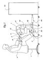
- the installation shown in Figures 1, 2, 3 and 6 includes a housing 1 equipped with two sensors 11 and 12 arranged at the casing 1 casing, so that a user U seated on a seat S can put his hands on sensor 11 and its feet on sensor 12.
- Each CCD matrix forms a network of photo-sensitive cells which generate a signal whose voltage is proportional to the brightness of the part of the signal S ' 1 or S' 2 which they perceive from the sensor 11 or 12.
- the output voltage of each cell varies linearly from 0 to 255 from black to white, which is commonly called "luminance scale" in the fields of computer science or television .
- Luminance is sometimes symbolized in video or computer systems by the variable Y.
- the cameras 21 and 22 are capable of supplying a processing unit 30 with video signals S 1 and S 2 representative of optical signals S ' 1 and S' 2 that they perceive, in particular from the luminance of these signals.
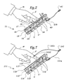
- the sensors 11 and 12 are identical and the sensor 11, which appears partially in Figure 2, includes a plate insulator 13 made for example of plastic.
- a spacer 14 makes it possible to define between the plate 13 and a second insulating plate 15, a volume V for receiving a liquid electrolyte 16, transparent or translucent, such as gel of the type used in electro-cardiography or for ultrasound or liquid soap.
- Plates 13 and 15 can be made of glass or plastic of the polymethacrylate type methyl or polyacrylic.
- a second spacer 17 is arranged on the edge of the plate 13 opposite volume V and supports a membrane flexible opaque 18 produced in an elastomer sheet, such than rubber, synthetic or natural, or silicone. Between the plate 13 and the membrane 18 is defined a volume V ' receiving a gas mixture 19 including argon, neon and carbon dioxide. These gases have the property remarkable to give rise to ionization phenomena I of different colors, namely blue for argon, orange for neon and green for carbon dioxide, these phenomena ionization taking place at ionization potentials different and predetermined. These ionization phenomena are obtained by displacement of electric charges under the effect of the potential difference between the object, i.e. by example the finger (s), and the electrolyte 16, these displacements of charges giving rise to photons. These ionization phenomena occur at voltage values lower than the trigger or discharge threshold values of gases considered, so that the system of the invention does not induce the creation of arcs or electric shocks potentially dangerous.
- a variable alternating voltage generator 40 is connected to the electrolytes 16 of the sensors 11 and 12 by electrical connections 41, respectively 42.
- the connections 41 and 42 make it possible to apply between these electrolytes 16 and through the body of the user a voltage variable alternative U whose frequency we denote by f .
- this differential mode creates a voltage difference, on the one hand, between the user's fingers d and the electrolyte 16 of the sensor 11 and , on the other hand, between its feet p or its toes o and the electrolyte 16 of the sensor 12.
- the conductor forming the line 41 is connected to a terminal 41 b bearing against the surface of the plate 15 opposite the volume V and held in position by a metal screw 43 which runs right through the plate 15, so that it is in electrical contact with the electrolyte 16.
- the user can place his two hands m on the sensor 11 and his two feet p on the sensor 12, twenty zones of potential ionization being controlled, which correspond respectively to the positions of the ends of the fingers and toes of the user.
- the pressure exerted by the user's finger d allows this membrane to be deformed to the point of expelling the gas mixture located between the membrane 18 and the plate 13 at the finger.
- the gas mixture is thus distributed around the finger and is capable of being ionized when the voltage difference U is within a predetermined range which depends on the nature of the mixture 19.
- the volume of gas or gas mixture 19 used in the sensor 11 is not very important, which is significant economically and as regards the safety of the user and the operator.
- the opaque nature of the membrane 18 allows the cameras 21 and 22 to effectively detect ionization phenomena I as of their appearance because these occur in the visible spectrum, while the cameras are isolated from the exterior light through the housing 1 and the membrane 18.
- the voltage U is gradually increased by stages P 1 , P 2 ... P i ... P N , as represented by the curve C 1 in FIG. 4.
- the central points of the various stages of this curve can be linked by a straight line D 1 which can be considered as an approximation of the curve C 1 .
- the rise in voltage along the curve C 1 is synchronized with the acquisition speed of the cameras 21 and 22.
- the duration of each level P i is 40ms, a plateau P i being thus visualized by means of two image frames on each signal S 1 or S 2 .
- Luminance is defined as the light intensity of the signal S ' 1 or S' 2 observed.
- the voltage U thus increases up to a value U 1 from which a maximum luminance L 1 is obtained.
- t 1 the instant when the voltage U reaches the value U 1 .
- ⁇ the angle of slope offset between the lines D 1 and D 2 .
- This angle can be considered as an energy index characteristic of the object studied, in this case the user's finger d.
- the frequency f of the voltage U is modulated by the generator 40 in a frequency range between approximately 1000 Hz and approximately 800 kHz.
- a luminance value L 4 equal to approximately 50% of the value L 1 and we denote by U 4 the corresponding voltage value obtained at the same time t 4 as the luminance L 4 .
- the frequency f of the voltage U 4 delivered by the generator 40 is continuously varied and the variation in the luminance as observed by the curve C 4 is observed.
- the luminance gradually increases until reaching, at an instant t 4 , a maximum value L ' 4 relative for the voltage U 4 ; then the luminance decreases.
- the frequency f 4 corresponding to the maximum value L ′ 4 is then identified and this frequency f 4 is defined as the energy frequency of the object studied, that is to say the frequency at which a maximum relative luminance L ' 4 is obtained, which can be assimilated to an electromagnetic resonance frequency.
- the part of the volume V 'surrounding the end of the finger d is divided into angular sectors ⁇ 1 to ⁇ 8 in each of which ionization phenomena I occur and in each of which one can determine characteristic values U 2 , U 3 , ⁇ and f 4 as indicated above.
- ionization phenomena occur in these sectors at separate times and for different voltages.
- the number and the definition of the sectors ⁇ 1 to ⁇ 8 depend on the choices made during modeling.
- the unit 30 is shown diagrammatically in FIG. 6 and comprises a first module 31 for acquiring the video signals S 1 and S 2 , a second module 32 for recognizing shapes allowing it to locate the support zone of each finger d on sensor 11 or each toe o on sensor 12 and define the sectors ⁇ 1 to ⁇ 8 .
- a module 33 for quantifying the luminance by zone makes it possible to analyze the signals S 1 and S 2 coming from the module 32, the corresponding signals then being transmitted to a computer 34 capable of performing the logic operations previously envisaged for determining the values characteristics U 2 , U 3 , ⁇ and f 4 .
- the computer 34 is connected to an interface 35 which is connected to the generator 40 and makes it possible to control it and to constantly know the values of the voltage and the frequency generated.
- the computer 34 is also connected to a base of data 36 in which reference values are stored characteristic quantities for known objects, this which allows a comparison between the determined quantities during each experience and these known objects.
- a monitor 37 is also provided to make known to the user the result of the operations carried out by the computer 34, this monitor for controlling a module 38 for controlling the interface 35.
- a device 39 provides access to a network internal or external IT for the confrontation of data and / or access to additional reference data.
- the entire unit 30 can be integrated into a computer incorporated in case 1 or connected to it by a suitable link 44.
- the final step of the method consists in attaching the detected characteristic values U 2 , U 3 , ⁇ and f 4 to each sector ⁇ 1 to ⁇ 8 , to allow a quantitative and qualitative analysis.
- the sensor 111 of this embodiment comprises two separate insulating plates 113 and 115 by a spacer 114 and defining between them a volume V making it possible to receive a liquid electrolyte which can be connected by a conductor 141 a of a connection 141 to a generator (not shown) of the type of generator 40.
- a second conductor 141 c connects the opposite terminal of the generator and the user's finger d , which makes it possible to directly apply a predetermined voltage between this finger and the electrolyte 116.
- the generator then operates in common mode and the measurement can be limited to only finger d, without necessity for the user to place the feet on the sensor 12.
- the conductor 141 c can be brought into contact with the finger d by means of a conductive patch 141 d of the type used in electrocardiography.
- the potential originating from the generator can be applied by the conductor 141 c to the wrist of the user, the latter being able to apply the five fingers of the hand to the sensor 111.
- a layer 117 of transparent plastic foam for example based on polymer, comprising micro-cells in which a gas or gas mixture is trapped 119 of the type of the mixture 19.
- An opaque coating 118 is disposed on layer 117 and isolates this layer from the atmosphere ambient by trapping the gas or mixture 119.
- the coating 118 is flexible and therefore constitutes a membrane delimiting the volume V 'of the layer 117 in which the mixture is confined 119.
- a user can deform the coating 118 and the layer 117 when he presses the end of a finger d, which has the effect of driving the gas mixture around this finger.
- the ionization phenomena I can be viewed transparently through the plates 113 and 115 and electrolyte 116, which are transparent like the plates 13 and 15 and the electrolyte 16.
- the sensor 11 of the first embodiment can be used with a common mode voltage supply, then that sensor 111 can be used with a device voltage supply in differential mode, this resulting operator choice.
- the electrolyte 16 or 116 constitutes a first armature of a capacitor, the second armature of which is constituted by the object to be studied, for example the finger d or the toe of a user.
- the present invention can be used for the characterization of biological bodies and, in particular, the determination of the biological properties of a human body, animal or plant. It can be used by a practitioner for the determination of meridians within the meaning of acupuncture, the flow path of an energetic fluid, such as blood of a mammal or the sap of a plant, the latter application of the invention making it possible to control the biological characteristics of plants with a view to their selection.
- the invention makes it possible in particular to compare the characteristics of plants between them, for example biological characteristics of plants obtained by crops of different types, organic, intensive or Transgenic.
- Another particularly important application of the invention relates to dimensional, structural or the condition of mechanical or electrical parts, to the extent where more concentrated areas of electrical shock can be observed on a part with micro-cracks, lines of weakness or surface defects.
- the invention can also be used in the field hydrology, for example for an analytical approach to the composition of water, and in the area of research fundamental, especially for cell differentiation of neighboring structure.
Landscapes
- Health & Medical Sciences (AREA)
- Life Sciences & Earth Sciences (AREA)
- Molecular Biology (AREA)
- Physics & Mathematics (AREA)
- Heart & Thoracic Surgery (AREA)
- Animal Behavior & Ethology (AREA)
- Chemical Kinetics & Catalysis (AREA)
- General Physics & Mathematics (AREA)
- Nuclear Medicine, Radiotherapy & Molecular Imaging (AREA)
- Radiology & Medical Imaging (AREA)
- Biophysics (AREA)
- Pathology (AREA)
- Engineering & Computer Science (AREA)
- Biomedical Technology (AREA)
- Chemical & Material Sciences (AREA)
- Medical Informatics (AREA)
- Surgery (AREA)
- Electrochemistry (AREA)
- General Health & Medical Sciences (AREA)
- Public Health (AREA)
- Veterinary Medicine (AREA)
- Investigating Or Analysing Materials By Optical Means (AREA)
- Measuring And Recording Apparatus For Diagnosis (AREA)
- Analysing Materials By The Use Of Radiation (AREA)
- Other Investigation Or Analysis Of Materials By Electrical Means (AREA)
- Transition And Organic Metals Composition Catalysts For Addition Polymerization (AREA)
- Geophysics And Detection Of Objects (AREA)
- Investigating Or Analyzing Materials Using Thermal Means (AREA)
- Investigating Or Analyzing Materials By The Use Of Electric Means (AREA)
- Measurement Of The Respiration, Hearing Ability, Form, And Blood Characteristics Of Living Organisms (AREA)
Claims (11)
- Verfahren zur Bestimmung von physikalischen Eigenschaften eines Objektes (m, p, d), bei dem:dadurch gekennzeichnet, dass es darin besteht:man das Objekt mit einem Aufnehmer (11,12,111) in Kontakt bringt, dessen leitendes Element (16,116) elektrisch mit einem Spannungsgenerator (40) verbunden ist;man eine Wechselspannung (U) zwischen das Objekt und das Element anlegt;man ein optisches Signal (S1', S2'), das die Menge an Ionisationslicht mindestens eines Gases (19,119) in der Nähe des Objektes darstellt, sichtbar macht und/oder aufzeichnet,die Spannung (U) bis zu einem Endwert (U1), bei dem die maximale Leuchtdichte (L1) beobachtet wird, fortschreitend zu erhöhen;als ersten Kennwert des Objektes den Wert der Spannung (U2) zu bestimmen, ab dem die Leuchtdichte (L2) des Signals größer oder gleich ungefähr 10% der maximalen Leuchtdichte ist undals zweiten Kennwert des Objektes den Wert der Spannung (U3) zu bestimmen, ab dem die Leuchtdichte (L3) des Signals größer oder gleich ungefähr 90% der maximalen Leuchtdichte ist.
- Verfahren nach Anspruch 1, dadurch gekennzeichnet, dass es darin besteht, die Spannung in Stufen (Pi) zu erhöhen, wobei jede Stufe der Erfassung eines Bildes des Signals (S1', S2') entspricht.
- Verfahren nach einem der vorhergehenden Ansprüche, dadurch gekennzeichnet, dass es darin besteht als anderen Kennwert des Objektes (m, p, d) einen Phasenverschiebungswinkel (Φ) zwischen der Änderung der Leuchtdichte (L1-L3) und der Änderung der Spannung (U0-U3) über die Zeit zu bestimmen, wobei der Winkel definiert ist als die Differenz der Steigung zwischen einer ersten Geraden (D1), die repräsentativ für die Steigerung der Spannung (U) über die Zeit ist, und einer zweiten Geraden, die repräsentativ für eine lineare Entwicklung der Leuchtdichte über die Zeit ist, zwischen den Momenten (A2, A3), bei denen die Leuchtdichte Werte (L2, L3) aufweist, die jeweils ungefähr gleich 10% und ungefähr gleich 90% der maximalen Leuchtdichte (L1) sind.
- Verfahren nach einem der vorhergehenden Ansprüche, dadurch gekennzeichnet, dass es darin besteht, die Spannung (U) in Stufen (Pi) zu erhöhen und die Frequenz (f) der Spannung auf jeder Stufe zu ändern.
- Verfahren nach einem der vorhergehenden Ansprüche, dadurch gekennzeichnet, dass es darin besteht als anderen Kennwert des Objektes den Wert der Frequenz (f4) der Spannung (U) entsprechend einer relativen maximalen Leuchtdichte (L'4) zu bestimmen, wenn die Frequenz (f) variiert, wobei die Spannung auf einem Stufenwert (U4) entsprechend
einer Zwischenleuchtdichte (L4), nämlich gleich ungefähr 50% der maximalen Leuchtdichte (L1) gehalten wird. - Verfahren nach einem der vorhergehenden Ansprüche, dadurch gekennzeichnet, dass es darin besteht, eine definierte Messfläche um das Objekt (d) herum auf den Aufnehmer (11) in individuelle Messzonen (Σ1- Σ8) aufzuteilen und die Kennwerte (U2, U3, δ, f4) für jede individuelle Messzone zu bestimmen.
- Verfahren nach einem der vorhergehenden Ansprüche, dadurch gekennzeichnet, dass es darin besteht, die physikalischen Eigenschaften eines menschlichen
oder tierischen Körpers zu messen, indem gleichzeitig die zehn Finger (d) eines Subjektes auf mindestens einen Aufnehmer (11) und die zehn Zehen (0) des Subjektes auf mindestens einen anderen Aufnehmer (12) aufgebracht werden, die leitenden Elemente (16) dieser Aufnehmer in differentieller Weise von einem Spannungsgenerator (40) zu versorgen und die Kennwerte für die zehn Finger und die zehn Zehen in paralleler Weise zu bestimmen. - Einrichtung zur Durchführung eines Verfahrens nach einem der vorhergehenden Ansprüche für die Bestimmung der physikalischen Eigenschaften eines Objektes (m, p, d), wobei die Einrichtung umfasst:dass der Aufnehmer mit einem Generator (40) verbunden ist, um eine Spannung (V) zwischen dem Objekt (m, p, d) und dem leitenden Element zu erzeugen und dass Mittel (30) zur Behandlung des optischen Signals (S1, S2) und zur Steuerung des Generators vorgesehen sind, die für die Durchführung eines Verfahrens nach einem der vorhergehenden Ansprüche angeordnet sind.einen Aufnehmer (11,12,111), der eine elektrisch isolierende Platte (13,113) und ein elektrisch leitendes Element (16,116) umfasst;Mittel (40) zur elektrischen Versorgung des elektrisch leitenden Elementes und des Objektes mit einer veränderlichen Wechselspannung (U) undMittel (21,22,30) zur Sichtbarmachung und/oder Aufzeichnung über die Platte und das leitende Element eines optischen Signals (S1, S2), das für die Menge des Ionisationslichtes (L) des Objektes aufgrund der ausgelegten Spannung repräsentativ ist, dadurch gekennzeichnet, dass der Aufnehmer eine biegsame Membran (18,118) umfasst, die mit der Platte (13,113) ein Volumen (V')zum Einschließen eines Gases oder einer Gasmischung begrenzt, das oder die unter der Wirkung der Spannung (U) sich ionisieren kann,
- Einrichtung nach Anspruch 8, dadurch gekennzeichnet, dass die biegsame Membran opak ist.
- Einrichtung nach einem der Ansprüche 8 oder 9, dadurch gekennzeichnet, dass das Gas oder die Gasmischung (119) in einem Schaum aus verformbarem Kunststoffmaterial (117) eingeschlossen ist.
- Einrichtung nach einem der Ansprüche 8 bis 10, dadurch gekennzeichnet, dass sie Mittel (32) zur Formerkennung, Mittel (33) zur Quantifizierung der Leuchtdichte des beobachten Signals (S1', S2'), Mittel (38) zur Steuerung der Mittel (40) zur elektrischen Versorgung, Mittel (34) zur automatischen Bestimmung von Kennwerten (U2, U3, Φ, f4) des Objektes (m, p, d), Mittel (36) zum Vergleich mit Referenzwerten und/oder Mittel (37) zur Sichtbarmachung von Ergebnissen der Bestimmung oder des Vergleichs umfasst.
Applications Claiming Priority (3)
| Application Number | Priority Date | Filing Date | Title |
|---|---|---|---|
| FR0000241 | 2000-01-10 | ||
| FR0000241A FR2803661B1 (fr) | 2000-01-10 | 2000-01-10 | Procede et installation de determination des proprietes physiques d'un objet |
| PCT/FR2001/000047 WO2001051998A1 (fr) | 2000-01-10 | 2001-01-08 | Procede et installation de determination des proprietes physiques d'un objet |
Publications (2)
| Publication Number | Publication Date |
|---|---|
| EP1247144A1 EP1247144A1 (de) | 2002-10-09 |
| EP1247144B1 true EP1247144B1 (de) | 2004-09-08 |
Family
ID=8845746
Family Applications (1)
| Application Number | Title | Priority Date | Filing Date |
|---|---|---|---|
| EP01903888A Expired - Lifetime EP1247144B1 (de) | 2000-01-10 | 2001-01-08 | Verfahren und einrichtung zur bestimmung der physikalischen eigenschaften eines objektes |
Country Status (12)
| Country | Link |
|---|---|
| US (1) | US20030095316A1 (de) |
| EP (1) | EP1247144B1 (de) |
| CN (1) | CN1224370C (de) |
| AT (1) | ATE275739T1 (de) |
| AU (1) | AU774963B2 (de) |
| BR (1) | BR0107482A (de) |
| CA (1) | CA2397098A1 (de) |
| DE (1) | DE60105388T2 (de) |
| ES (1) | ES2227120T3 (de) |
| FR (1) | FR2803661B1 (de) |
| PT (1) | PT1247144E (de) |
| WO (1) | WO2001051998A1 (de) |
Families Citing this family (6)
| Publication number | Priority date | Publication date | Assignee | Title |
|---|---|---|---|---|
| RU2217047C2 (ru) * | 2001-12-21 | 2003-11-27 | Коротков Константин Георгиевич | Способ диагностики состояния организма человека |
| US7697827B2 (en) | 2005-10-17 | 2010-04-13 | Konicek Jeffrey C | User-friendlier interfaces for a camera |
| GEP20084574B (en) * | 2007-03-16 | 2008-12-25 | Marina Shaduri | Device for gas-discharge survey for detection of malignant processes in living organisms |
| US20110115892A1 (en) * | 2009-11-13 | 2011-05-19 | VisionBrite Technologies, Inc. | Real-time embedded visible spectrum light vision-based human finger detection and tracking method |
| CN103906465B (zh) * | 2011-08-15 | 2017-07-07 | 埃派克研究与诊断有限公司 | 来自指尖或脚趾附近的光度的局部生理状态 |
| DE102012017928B4 (de) * | 2012-09-12 | 2025-10-16 | Michael König | Vorrichtung zur gleichzeitigen Aufzeichnung von Koronaentladungen an mehreren biologischen und nichtbiologischen Objekten und deren automatisierte und halbautomatisierte Auswertung |
Family Cites Families (6)
| Publication number | Priority date | Publication date | Assignee | Title |
|---|---|---|---|---|
| US3994283A (en) * | 1975-05-14 | 1976-11-30 | Farley Glenn R | Glow pattern viewing cell and apparatus for living organisms |
| DE2754031A1 (de) * | 1977-12-05 | 1979-06-13 | Mandel Peter Friedrich | Diagnosegeraet |
| DE3605104A1 (de) * | 1986-02-18 | 1987-08-20 | Johannes Chr Koziol | Elektrische wechselfeld durchleuchtung |
| FR2646519B1 (fr) * | 1989-04-27 | 1991-08-23 | Charpak Georges | Procede et dispositif pour determiner la distribution des rayons (beta) emergeant d'une surface |
| WO1999009578A1 (en) * | 1997-08-14 | 1999-02-25 | Matsushita Electric Industrial Co., Ltd. | Gas discharge panel and gas light-emitting device |
| FR2781046B1 (fr) * | 1998-07-10 | 2000-09-29 | Pascal Herbepin | Procede et dispositif de determination de proprietes physiques d'un objet |
-
2000
- 2000-01-10 FR FR0000241A patent/FR2803661B1/fr not_active Expired - Fee Related
-
2001
- 2001-01-08 PT PT01903888T patent/PT1247144E/pt unknown
- 2001-01-08 AU AU31853/01A patent/AU774963B2/en not_active Ceased
- 2001-01-08 DE DE60105388T patent/DE60105388T2/de not_active Expired - Lifetime
- 2001-01-08 WO PCT/FR2001/000047 patent/WO2001051998A1/fr not_active Ceased
- 2001-01-08 CN CNB018035744A patent/CN1224370C/zh not_active Expired - Fee Related
- 2001-01-08 ES ES01903888T patent/ES2227120T3/es not_active Expired - Lifetime
- 2001-01-08 BR BR0107482-2A patent/BR0107482A/pt not_active IP Right Cessation
- 2001-01-08 CA CA002397098A patent/CA2397098A1/fr not_active Abandoned
- 2001-01-08 AT AT01903888T patent/ATE275739T1/de not_active IP Right Cessation
- 2001-01-08 EP EP01903888A patent/EP1247144B1/de not_active Expired - Lifetime
- 2001-01-08 US US10/169,507 patent/US20030095316A1/en not_active Abandoned
Also Published As
| Publication number | Publication date |
|---|---|
| FR2803661B1 (fr) | 2002-04-05 |
| AU774963B2 (en) | 2004-07-15 |
| ATE275739T1 (de) | 2004-09-15 |
| PT1247144E (pt) | 2005-01-31 |
| FR2803661A1 (fr) | 2001-07-13 |
| ES2227120T3 (es) | 2005-04-01 |
| CN1224370C (zh) | 2005-10-26 |
| CA2397098A1 (fr) | 2001-07-19 |
| EP1247144A1 (de) | 2002-10-09 |
| BR0107482A (pt) | 2002-09-03 |
| DE60105388T2 (de) | 2005-09-15 |
| US20030095316A1 (en) | 2003-05-22 |
| WO2001051998A1 (fr) | 2001-07-19 |
| AU3185301A (en) | 2001-07-24 |
| DE60105388D1 (de) | 2004-10-14 |
| CN1394299A (zh) | 2003-01-29 |
Similar Documents
| Publication | Publication Date | Title |
|---|---|---|
| US6251070B1 (en) | Device and a method for measuring skin parameters | |
| EP1277436B1 (de) | Instrument zur Beobachtung der Haut oder der Haare | |
| EP2661222B1 (de) | System und verfahren zur analyse von mindestens einer eigenschaft der haut | |
| US6219143B1 (en) | Method and apparatus for analyzing shearogram images by animation | |
| CA2391882A1 (fr) | Dispositif permettant de determiner le degre d'une caracteristique de la typologie corporelle | |
| CA2033688A1 (fr) | Capteur d'humidite et installation de mesure comportant une pluralite de tels capteurs | |
| WO2007074305A1 (fr) | Conditionnement avec capteur integre | |
| CA1117787A (fr) | Appareil de determination de la quantite de sebum secretee par une peau | |
| EP1177766A1 (de) | Verfahren zur Erfassung von nicht-dermatoglyphischem Hautbereich oder Haarbereich mittels einer Erfassungsvorrichtung mit einem nicht-optischen Detektor | |
| EP1247144A1 (de) | Verfahren und einrichtung zur bestimmung der physikalischen eigenschaften eines objektes | |
| FR2710517A1 (fr) | Procédé d'évaluation de l'état d'hydratation de la peau et appareil destiné à sa mise en Óoeuvre. | |
| WO1991014399A1 (fr) | Papillometre | |
| FR2568391A1 (fr) | Systeme pour la simulation de modelage ou de massage de tout ou partie d'un corps humain | |
| FR2523727A1 (fr) | Perfectionnements aux dispositifs de mesure des charges electriques portees par un dielectrique | |
| CA2318360C (fr) | Dispositif de prise d'empreintes digitales | |
| FR2679759A1 (fr) | Materiel de test d'acuite visuelle et/ou de sensibilite aux contrastes spatiaux chez l'homme, dispositif et procede de fabrication correspondants. | |
| US5526113A (en) | Method and apparatus for measurement of spatial signal and noise power of imaging systems | |
| EP1659381A1 (de) | Vorrichtung zum Erkennen von Farben | |
| FR2781046A1 (fr) | Procede et dispositif de determination de proprietes physiques d'un objet | |
| FR2789883A1 (fr) | Dispositif de visualisation | |
| FR2552220A1 (fr) | Procede et dispositif pour mesurer les parties en creux (sulcus cutis) de la peau humaine | |
| FR2787988A1 (fr) | Dispositif de prise d'empreintes | |
| EP0414783A1 (de) | Vorrichtung und verfahren zur automatischen bestimmung physikalisch chemischer parameter in einem los von getreide | |
| FR2915008A1 (fr) | Procede de detection du caractere vivant d'une zone corporelle et dispositif optique pour la mise en oeuvre de ce procede | |
| EP0376762B1 (de) | Verfahren und Vorrichtung zur Bestimmung der räumlichen Verteilung der aus der Oberfläche eines radioaktiven Körpers austretenden Elektronen |
Legal Events
| Date | Code | Title | Description |
|---|---|---|---|
| PUAI | Public reference made under article 153(3) epc to a published international application that has entered the european phase |
Free format text: ORIGINAL CODE: 0009012 |
|
| 17P | Request for examination filed |
Effective date: 20020627 |
|
| AK | Designated contracting states |
Kind code of ref document: A1 Designated state(s): AT BE CH CY DE DK ES FI FR GB GR IE IT LI LU MC NL PT SE TR |
|
| AX | Request for extension of the european patent |
Free format text: AL;LT;LV;MK;RO;SI |
|
| GRAP | Despatch of communication of intention to grant a patent |
Free format text: ORIGINAL CODE: EPIDOSNIGR1 |
|
| RIC1 | Information provided on ipc code assigned before grant |
Ipc: 7G 01N 21/63 B Ipc: 7G 03G 17/00 A Ipc: 7A 61B 5/00 B |
|
| GRAS | Grant fee paid |
Free format text: ORIGINAL CODE: EPIDOSNIGR3 |
|
| GRAA | (expected) grant |
Free format text: ORIGINAL CODE: 0009210 |
|
| AK | Designated contracting states |
Kind code of ref document: B1 Designated state(s): AT BE CH CY DE DK ES FI FR GB GR IE IT LI LU MC NL PT SE TR |
|
| PG25 | Lapsed in a contracting state [announced via postgrant information from national office to epo] |
Ref country code: NL Free format text: LAPSE BECAUSE OF FAILURE TO SUBMIT A TRANSLATION OF THE DESCRIPTION OR TO PAY THE FEE WITHIN THE PRESCRIBED TIME-LIMIT Effective date: 20040908 Ref country code: FI Free format text: LAPSE BECAUSE OF FAILURE TO SUBMIT A TRANSLATION OF THE DESCRIPTION OR TO PAY THE FEE WITHIN THE PRESCRIBED TIME-LIMIT Effective date: 20040908 Ref country code: TR Free format text: LAPSE BECAUSE OF FAILURE TO SUBMIT A TRANSLATION OF THE DESCRIPTION OR TO PAY THE FEE WITHIN THE PRESCRIBED TIME-LIMIT Effective date: 20040908 |
|
| REG | Reference to a national code |
Ref country code: GB Ref legal event code: FG4D Free format text: NOT ENGLISH |
|
| REG | Reference to a national code |
Ref country code: CH Ref legal event code: EP |
|
| REG | Reference to a national code |
Ref country code: IE Ref legal event code: FG4D Free format text: FRENCH |
|
| REF | Corresponds to: |
Ref document number: 60105388 Country of ref document: DE Date of ref document: 20041014 Kind code of ref document: P |
|
| PG25 | Lapsed in a contracting state [announced via postgrant information from national office to epo] |
Ref country code: SE Free format text: LAPSE BECAUSE OF FAILURE TO SUBMIT A TRANSLATION OF THE DESCRIPTION OR TO PAY THE FEE WITHIN THE PRESCRIBED TIME-LIMIT Effective date: 20041208 Ref country code: DK Free format text: LAPSE BECAUSE OF FAILURE TO SUBMIT A TRANSLATION OF THE DESCRIPTION OR TO PAY THE FEE WITHIN THE PRESCRIBED TIME-LIMIT Effective date: 20041208 Ref country code: GR Free format text: LAPSE BECAUSE OF FAILURE TO SUBMIT A TRANSLATION OF THE DESCRIPTION OR TO PAY THE FEE WITHIN THE PRESCRIBED TIME-LIMIT Effective date: 20041208 |
|
| PG25 | Lapsed in a contracting state [announced via postgrant information from national office to epo] |
Ref country code: LU Free format text: LAPSE BECAUSE OF NON-PAYMENT OF DUE FEES Effective date: 20050108 Ref country code: CY Free format text: LAPSE BECAUSE OF FAILURE TO SUBMIT A TRANSLATION OF THE DESCRIPTION OR TO PAY THE FEE WITHIN THE PRESCRIBED TIME-LIMIT Effective date: 20050108 |
|
| PG25 | Lapsed in a contracting state [announced via postgrant information from national office to epo] |
Ref country code: MC Free format text: LAPSE BECAUSE OF NON-PAYMENT OF DUE FEES Effective date: 20050131 |
|
| REG | Reference to a national code |
Ref country code: PT Ref legal event code: SC4A Effective date: 20041119 |
|
| GBT | Gb: translation of ep patent filed (gb section 77(6)(a)/1977) |
Effective date: 20050118 |
|
| LTIE | Lt: invalidation of european patent or patent extension |
Effective date: 20040908 |
|
| NLV1 | Nl: lapsed or annulled due to failure to fulfill the requirements of art. 29p and 29m of the patents act | ||
| REG | Reference to a national code |
Ref country code: ES Ref legal event code: FG2A Ref document number: 2227120 Country of ref document: ES Kind code of ref document: T3 |
|
| PLBE | No opposition filed within time limit |
Free format text: ORIGINAL CODE: 0009261 |
|
| STAA | Information on the status of an ep patent application or granted ep patent |
Free format text: STATUS: NO OPPOSITION FILED WITHIN TIME LIMIT |
|
| 26N | No opposition filed |
Effective date: 20050609 |
|
| PGFP | Annual fee paid to national office [announced via postgrant information from national office to epo] |
Ref country code: CH Payment date: 20081215 Year of fee payment: 9 |
|
| PGFP | Annual fee paid to national office [announced via postgrant information from national office to epo] |
Ref country code: PT Payment date: 20081222 Year of fee payment: 9 |
|
| PGFP | Annual fee paid to national office [announced via postgrant information from national office to epo] |
Ref country code: AT Payment date: 20081219 Year of fee payment: 9 Ref country code: ES Payment date: 20090122 Year of fee payment: 9 Ref country code: IE Payment date: 20090105 Year of fee payment: 9 |
|
| PGFP | Annual fee paid to national office [announced via postgrant information from national office to epo] |
Ref country code: GB Payment date: 20090109 Year of fee payment: 9 |
|
| PGFP | Annual fee paid to national office [announced via postgrant information from national office to epo] |
Ref country code: BE Payment date: 20090205 Year of fee payment: 9 |
|
| PGFP | Annual fee paid to national office [announced via postgrant information from national office to epo] |
Ref country code: IT Payment date: 20090123 Year of fee payment: 9 |
|
| REG | Reference to a national code |
Ref country code: PT Ref legal event code: MM4A Free format text: LAPSE DUE TO NON-PAYMENT OF FEES Effective date: 20100708 |
|
| BERE | Be: lapsed |
Owner name: *REYNES JEAN-LOUIS Effective date: 20100131 Owner name: *HERBEPIN PASCAL Effective date: 20100131 Owner name: *CANETOS JEAN Effective date: 20100131 |
|
| REG | Reference to a national code |
Ref country code: CH Ref legal event code: PL |
|
| GBPC | Gb: european patent ceased through non-payment of renewal fee |
Effective date: 20100108 |
|
| REG | Reference to a national code |
Ref country code: IE Ref legal event code: MM4A |
|
| PG25 | Lapsed in a contracting state [announced via postgrant information from national office to epo] |
Ref country code: CH Free format text: LAPSE BECAUSE OF NON-PAYMENT OF DUE FEES Effective date: 20100131 Ref country code: LI Free format text: LAPSE BECAUSE OF NON-PAYMENT OF DUE FEES Effective date: 20100131 |
|
| PG25 | Lapsed in a contracting state [announced via postgrant information from national office to epo] |
Ref country code: AT Free format text: LAPSE BECAUSE OF NON-PAYMENT OF DUE FEES Effective date: 20100108 |
|
| PG25 | Lapsed in a contracting state [announced via postgrant information from national office to epo] |
Ref country code: GB Free format text: LAPSE BECAUSE OF NON-PAYMENT OF DUE FEES Effective date: 20100108 |
|
| PG25 | Lapsed in a contracting state [announced via postgrant information from national office to epo] |
Ref country code: PT Free format text: LAPSE BECAUSE OF NON-PAYMENT OF DUE FEES Effective date: 20100708 Ref country code: IE Free format text: LAPSE BECAUSE OF NON-PAYMENT OF DUE FEES Effective date: 20100108 |
|
| PG25 | Lapsed in a contracting state [announced via postgrant information from national office to epo] |
Ref country code: BE Free format text: LAPSE BECAUSE OF NON-PAYMENT OF DUE FEES Effective date: 20100131 |
|
| PG25 | Lapsed in a contracting state [announced via postgrant information from national office to epo] |
Ref country code: IT Free format text: LAPSE BECAUSE OF NON-PAYMENT OF DUE FEES Effective date: 20100108 |
|
| REG | Reference to a national code |
Ref country code: ES Ref legal event code: FD2A Effective date: 20110407 |
|
| PG25 | Lapsed in a contracting state [announced via postgrant information from national office to epo] |
Ref country code: ES Free format text: LAPSE BECAUSE OF NON-PAYMENT OF DUE FEES Effective date: 20110328 |
|
| PG25 | Lapsed in a contracting state [announced via postgrant information from national office to epo] |
Ref country code: ES Free format text: LAPSE BECAUSE OF NON-PAYMENT OF DUE FEES Effective date: 20100109 |
|
| PGFP | Annual fee paid to national office [announced via postgrant information from national office to epo] |
Ref country code: FR Payment date: 20120125 Year of fee payment: 12 |
|
| PGFP | Annual fee paid to national office [announced via postgrant information from national office to epo] |
Ref country code: DE Payment date: 20120118 Year of fee payment: 12 |
|
| REG | Reference to a national code |
Ref country code: FR Ref legal event code: ST Effective date: 20130930 |
|
| PG25 | Lapsed in a contracting state [announced via postgrant information from national office to epo] |
Ref country code: DE Free format text: LAPSE BECAUSE OF NON-PAYMENT OF DUE FEES Effective date: 20130801 |
|
| REG | Reference to a national code |
Ref country code: DE Ref legal event code: R119 Ref document number: 60105388 Country of ref document: DE Effective date: 20130801 |
|
| PG25 | Lapsed in a contracting state [announced via postgrant information from national office to epo] |
Ref country code: FR Free format text: LAPSE BECAUSE OF NON-PAYMENT OF DUE FEES Effective date: 20130131 |