EP1247604A1 - Fraise pour orfèvrerie et sertissage - Google Patents
Fraise pour orfèvrerie et sertissage Download PDFInfo
- Publication number
- EP1247604A1 EP1247604A1 EP01121235A EP01121235A EP1247604A1 EP 1247604 A1 EP1247604 A1 EP 1247604A1 EP 01121235 A EP01121235 A EP 01121235A EP 01121235 A EP01121235 A EP 01121235A EP 1247604 A1 EP1247604 A1 EP 1247604A1
- Authority
- EP
- European Patent Office
- Prior art keywords
- cutting
- milling tool
- contour
- fingers
- cutting head
- Prior art date
- Legal status (The legal status is an assumption and is not a legal conclusion. Google has not performed a legal analysis and makes no representation as to the accuracy of the status listed.)
- Withdrawn
Links
- 238000003801 milling Methods 0.000 title claims description 36
- 238000005520 cutting process Methods 0.000 claims abstract description 120
- 238000000034 method Methods 0.000 claims abstract description 10
- 239000002184 metal Substances 0.000 claims abstract description 9
- 229910052751 metal Inorganic materials 0.000 claims abstract description 9
- 239000000463 material Substances 0.000 claims description 9
- 238000004519 manufacturing process Methods 0.000 claims description 8
- 238000000227 grinding Methods 0.000 claims description 4
- 238000003754 machining Methods 0.000 claims description 4
- 229910001315 Tool steel Inorganic materials 0.000 claims description 3
- 150000002739 metals Chemical class 0.000 claims description 3
- 239000010970 precious metal Substances 0.000 claims description 3
- 230000002093 peripheral effect Effects 0.000 abstract 1
- 239000010437 gem Substances 0.000 description 8
- 229910001751 gemstone Inorganic materials 0.000 description 7
- 229910000831 Steel Inorganic materials 0.000 description 4
- 239000010959 steel Substances 0.000 description 4
- BASFCYQUMIYNBI-UHFFFAOYSA-N platinum Chemical compound [Pt] BASFCYQUMIYNBI-UHFFFAOYSA-N 0.000 description 2
- 238000005219 brazing Methods 0.000 description 1
- 230000000694 effects Effects 0.000 description 1
- PCHJSUWPFVWCPO-UHFFFAOYSA-N gold Chemical compound [Au] PCHJSUWPFVWCPO-UHFFFAOYSA-N 0.000 description 1
- 239000010931 gold Substances 0.000 description 1
- 229910052737 gold Inorganic materials 0.000 description 1
- 238000010348 incorporation Methods 0.000 description 1
- 229910052697 platinum Inorganic materials 0.000 description 1
- 238000005498 polishing Methods 0.000 description 1
- 238000007493 shaping process Methods 0.000 description 1
- 238000005476 soldering Methods 0.000 description 1
- 230000007704 transition Effects 0.000 description 1
Images

Classifications
-
- B—PERFORMING OPERATIONS; TRANSPORTING
- B23—MACHINE TOOLS; METAL-WORKING NOT OTHERWISE PROVIDED FOR
- B23C—MILLING
- B23C5/00—Milling-cutters
- B23C5/02—Milling-cutters characterised by the shape of the cutter
- B23C5/12—Cutters specially designed for producing particular profiles
- B23C5/14—Cutters specially designed for producing particular profiles essentially comprising curves
-
- B—PERFORMING OPERATIONS; TRANSPORTING
- B23—MACHINE TOOLS; METAL-WORKING NOT OTHERWISE PROVIDED FOR
- B23C—MILLING
- B23C5/00—Milling-cutters
- B23C5/02—Milling-cutters characterised by the shape of the cutter
- B23C5/10—Shank-type cutters, i.e. with an integral shaft
-
- B—PERFORMING OPERATIONS; TRANSPORTING
- B23—MACHINE TOOLS; METAL-WORKING NOT OTHERWISE PROVIDED FOR
- B23C—MILLING
- B23C2210/00—Details of milling cutters
- B23C2210/72—Rotatable in both directions
Definitions
- the invention has for its object to a milling tool create that avoids these disadvantages.
- the axially aligned cutting finger has that with respect on the axis of rotation and in the circumferential direction at a distance are arranged to each other and each on their inside directed side are provided with a cutting edge, the Contour is shaped so that when rotating, the one to be produced on the workpiece Contour is created.
- the Cutting the individual cutting fingers converge in the axis of rotation, so that the free end of the final workpiece contour to be machined.
- the cutting fingers are diametrically opposite and arranged in the circumferential direction at the same distance from each other are.
- the cutting edges of the opposite Cutting fingers one of the to be produced Represent the workpiece contour of the correspondingly shaped total cutting edge, which is a curved in a further embodiment of the invention Contour, preferably has a pitch circle contour.
- An arrangement of at least four cutting fingers on the cutting head, each with opposing cutting fingers form a total cutting edge with their cutting edges can be in simply geometrically by two crossing at 90 °, grooves on the free end of the cutting head produce. This creates the individual cutting fingers Cutting edges in the area of the free end of the cutting fingers by two each at an angle of 90 ° Boundary surfaces arise, so that from a higher Life expectancy can be assumed than with the milling tools that have been customary up to now with a cutting angle of approximately -10 °.
- the strenght the cutting finger can here with a given inner diameter of the cutting head due to the outer diameter can be varied.
- the invention further relates to a method of manufacture one with a clamping shank and a cutting head with axial aligned cutting fingers provided milling tool for Processing of metals according to claims 1 to 7.
- the method is characterized in that into a cutting head blank connected to the clamping shaft at least two intersecting at the end at an angle Grooves are incorporated.
- the incorporation of the grooves can even with a distance between the opposing cutting edges of only 0.6 mm with rotating tools, which in turn have a large diameter because it is only to the width of the groove to be manufactured Thickness and the contour of the tool to be generated arrives.
- the milling tool shown in Fig. 1 has a clamping shaft 1, which is firmly connected to a cutting head 2.
- the cutting head 2 is with axially aligned cutting fingers 3, four axially aligned in the illustrated embodiment Provide cutting fingers 3.
- each have a cutting edge 5 delimiting side surfaces 5.1 of a cutting finger 3 at an angle of 90 ° to each other.
- This cutting angle ⁇ is significantly less than the cutting angle available in the case of milling tools customary up to now of about -10 °.
- the obtuse angle is with regard to that relatively low hardness of the materials to be processed, usually precious metals, such as platinum or gold, due to the significantly higher hardness that can be used for the cutting head 2
- cutting materials are not a disadvantage.
- the milling tool can rotate in both directions of rotation be used.
- the cutting fingers 3 each face the axis of rotation 4 Cutting edges 5, so that the cutting edges 5 of each two opposite cutting fingers 3 one of the to be produced Display the corresponding total cutting edge of the workpiece contour.
- the cutting edges 5 and thus also the total cutting edge have a curved contour, preferably a pitch circle contour on, as can be seen in the sectional view of FIG. 3 is.
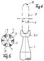
- FIG. 5 shows an embodiment with six cutting fingers 3, those for machining larger block diameters is appropriate.
- the angle of the cutting edges 5 with respect to the line of engagement L on the workpiece is 30 ° accordingly smaller.
- Such a method can be used in the process according to the invention
- Manufacture milling tool in that, as indicated in Fig. 6, into a cutting head blank connected to the clamping shaft 1 3.1 on the front side, for example, two under one Grooves 6 crossing angles of 90 ° (see FIG. 2) are incorporated become.
- This can, for example, as shown in FIG. 6 done by a rotating disc-shaped grinding tool 7.
- the diameter of the grinding tool 7 can be corresponding the specifications of the manufacturing facility are selected, because it is only for the manufacture of the milling tool Thickness d of the grinding wheel arrives.
- the cutting fingers 3 also from a cutting head 2 made of high-strength cutting materials be worked out.
- tool quality steels come also hardened steels in HSS quality and also sintered ones Hard materials, such as hard metals.
- the cutting head 2 can be integral with the Tension shaft 1 connected or from a higher quality Cutting material exist and for example by brazing be connected with a steel shank.
- the disk-shaped tool 7 has a working contour 8 on whose shape is based on the specification of the contour of the total cutting edge must be coordinated. Should be a partial circular cutting edge are produced as shown in Fig. 3, then the working contour 8 must accordingly the conic sections correspond to an ellipse.
- the total cutting edge should expediently form a pitch circle that is smaller is as a semicircle, so that the hand-held rotating Milling tool swinging around the central axis of the stub can be moved to a perfect dome-shaped smooth rounding of the free butt end without visible transition edge to the cylindrical part.
- Fig. 2 From supervision according to Fig. 2 is also derived that independently of the circumferential contour of the cutting head 2 that shown Cutting edge geometry and cutting contour always arises, if two or three intersecting grooves with same width d on the face in the cutting head blanks 3.1 be incorporated. This also gives you the opportunity even with very small working diameters D to be produced Milling tool cutting finger 3 with sufficient strength and thus to produce sufficient strength.
- Fig. 1 and Fig. 6 the two intersecting grooves 6 with their two longitudinal axes 6.1 run in a plane that is perpendicular to the axis of rotation 4 is aligned
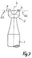
- Fig. 7 the Longitudinal axis 6.1 of one groove 6 perpendicular to the axis of rotation 4 aligned and the partial longitudinal axis 6.2 of the other groove each at an angle ⁇ falling against the clamping shaft 1 aligned.
- This shape is particularly common with tools larger working diameters D the advantage that even in Area of the axis of rotation 4 at least one pronounced cutting edge 5 is present, through which a still sufficient, if lower cutting performance is also achieved.
Landscapes
- Engineering & Computer Science (AREA)
- Mechanical Engineering (AREA)
- Milling Processes (AREA)
Priority Applications (1)
| Application Number | Priority Date | Filing Date | Title |
|---|---|---|---|
| EP01121235A EP1247604A1 (fr) | 2001-09-05 | 2001-09-05 | Fraise pour orfèvrerie et sertissage |
Applications Claiming Priority (1)
| Application Number | Priority Date | Filing Date | Title |
|---|---|---|---|
| EP01121235A EP1247604A1 (fr) | 2001-09-05 | 2001-09-05 | Fraise pour orfèvrerie et sertissage |
Publications (1)
| Publication Number | Publication Date |
|---|---|
| EP1247604A1 true EP1247604A1 (fr) | 2002-10-09 |
Family
ID=8178552
Family Applications (1)
| Application Number | Title | Priority Date | Filing Date |
|---|---|---|---|
| EP01121235A Withdrawn EP1247604A1 (fr) | 2001-09-05 | 2001-09-05 | Fraise pour orfèvrerie et sertissage |
Country Status (1)
| Country | Link |
|---|---|
| EP (1) | EP1247604A1 (fr) |
Cited By (2)
| Publication number | Priority date | Publication date | Assignee | Title |
|---|---|---|---|---|
| EP1371437A1 (fr) * | 2002-06-15 | 2003-12-17 | Busch & Co.KG | Fraise pour orfèvrerie et sertissage |
| CN116277231A (zh) * | 2023-04-21 | 2023-06-23 | 江苏伊顿航天材料股份有限公司 | 一种航天玻璃密封条用夹紧裁切装置 |
Citations (4)
| Publication number | Priority date | Publication date | Assignee | Title |
|---|---|---|---|---|
| DE609958C (de) * | 1935-02-27 | Ver Stahlwerke Akt Ges | Aus pilz- und halsfoermigem Teil bestehender Fraeser, insbesondere zur Bearbeitung de Aufspannschlitze von Schienenunterlagplatten | |
| FR1596458A (fr) * | 1968-06-05 | 1970-06-22 | ||
| DE2423035A1 (de) * | 1974-05-13 | 1975-11-27 | Astor Selbach | Vorrichtung zur erzeugung kugelfoermiger oder halbkugelfoermiger schnitte |
| FR2436555A1 (fr) * | 1978-09-19 | 1980-04-18 | Chatut Rene | Lame de scie circulaire concave pour debroussailleuse |
-
2001
- 2001-09-05 EP EP01121235A patent/EP1247604A1/fr not_active Withdrawn
Patent Citations (4)
| Publication number | Priority date | Publication date | Assignee | Title |
|---|---|---|---|---|
| DE609958C (de) * | 1935-02-27 | Ver Stahlwerke Akt Ges | Aus pilz- und halsfoermigem Teil bestehender Fraeser, insbesondere zur Bearbeitung de Aufspannschlitze von Schienenunterlagplatten | |
| FR1596458A (fr) * | 1968-06-05 | 1970-06-22 | ||
| DE2423035A1 (de) * | 1974-05-13 | 1975-11-27 | Astor Selbach | Vorrichtung zur erzeugung kugelfoermiger oder halbkugelfoermiger schnitte |
| FR2436555A1 (fr) * | 1978-09-19 | 1980-04-18 | Chatut Rene | Lame de scie circulaire concave pour debroussailleuse |
Cited By (3)
| Publication number | Priority date | Publication date | Assignee | Title |
|---|---|---|---|---|
| EP1371437A1 (fr) * | 2002-06-15 | 2003-12-17 | Busch & Co.KG | Fraise pour orfèvrerie et sertissage |
| CN116277231A (zh) * | 2023-04-21 | 2023-06-23 | 江苏伊顿航天材料股份有限公司 | 一种航天玻璃密封条用夹紧裁切装置 |
| CN116277231B (zh) * | 2023-04-21 | 2023-12-15 | 江苏伊顿航天材料股份有限公司 | 一种航天玻璃密封条用夹紧裁切装置 |
Similar Documents
| Publication | Publication Date | Title |
|---|---|---|
| DE10112286C1 (de) | Verfahren zur Herstellung eines chirurgischen Sägeblatts | |
| EP0316807B1 (fr) | Méthode d'usinage d'un pièce avec un outil ayant des arrêtes tranchantes à l'extrémité | |
| EP3694670B1 (fr) | Outil de taillage en développante | |
| CH647176A5 (de) | Verfahren zur herstellung von saegeblaettern und ein nach dem verfahren hergestelltes saegeblatt. | |
| DE102010061432A1 (de) | Verfahren zur Herstellung eines Zahnrades mit balligen Zähnen | |
| DE19901929C2 (de) | Dentalwerkzeug | |
| DE3415332A1 (de) | Verfahren zum herstellen eines raeumwerkzeugs | |
| WO2007096336A1 (fr) | Dispositif et procede de réalisation d'une decoupe en forme de calotte dans une piece par enlevement de matiere | |
| EP3974087A1 (fr) | Outil de fraisage et procédé de fabrication d'un tel outil de fraisage | |
| DE4405987C2 (de) | Schaftfräser | |
| EP3423233B1 (fr) | Outil de brunissage | |
| DE4340608A1 (de) | Schneidmesser | |
| EP3930598B1 (fr) | Instrument médical et procédé pour la fabrication d'un instrument médical | |
| EP3562425B1 (fr) | Outil de fraisage | |
| EP1247604A1 (fr) | Fraise pour orfèvrerie et sertissage | |
| EP3592492B1 (fr) | Outil destiné à tailler en développante ou à dresser un outil de finition comprenant une denture extérieure | |
| DE3810230C2 (fr) | ||
| DE2543275B2 (de) | Umfangs-Segmentschleifscheibe | |
| DE102023119340B3 (de) | Korneisen | |
| DE19516772C2 (de) | Kombiniertes Dreh-, Bohr- und Stechwerkzeug | |
| EP1112798B1 (fr) | Outil pour l'usinage de précision pour le finissage de pièces sous forme de roue dentée | |
| DE10324432B4 (de) | Profilgeschärftes Stabmesser zur Herstellung von Kegel- und Hypoidrädern und Verfahren zum Profilschärfen eines solchen Stabmessers | |
| DE102018129155B4 (de) | Verfahren zum Erzeugen eines Schmuckstückes | |
| EP3986680A1 (fr) | Procédé de fabrication de cisailles et combinaison d'au moins deux cisailles | |
| DE2539881A1 (de) | Zahnaerztliches drehwerkzeug, insbesondere fraeser |
Legal Events
| Date | Code | Title | Description |
|---|---|---|---|
| PUAI | Public reference made under article 153(3) epc to a published international application that has entered the european phase |
Free format text: ORIGINAL CODE: 0009012 |
|
| AK | Designated contracting states |
Kind code of ref document: A1 Designated state(s): AT BE CH CY DE DK ES FI FR GB GR IE IT LI LU MC NL PT SE TR |
|
| AX | Request for extension of the european patent |
Free format text: AL;LT;LV;MK;RO;SI |
|
| AKX | Designation fees paid |
Designated state(s): AT BE CH CY DE DK ES FI FR GB GR IE IT LI LU MC NL PT SE TR |
|
| STAA | Information on the status of an ep patent application or granted ep patent |
Free format text: STATUS: THE APPLICATION IS DEEMED TO BE WITHDRAWN |
|
| 18D | Application deemed to be withdrawn |
Effective date: 20030411 |