EP1247697A2 - Drehschalter - Google Patents
Drehschalter Download PDFInfo
- Publication number
- EP1247697A2 EP1247697A2 EP02006986A EP02006986A EP1247697A2 EP 1247697 A2 EP1247697 A2 EP 1247697A2 EP 02006986 A EP02006986 A EP 02006986A EP 02006986 A EP02006986 A EP 02006986A EP 1247697 A2 EP1247697 A2 EP 1247697A2
- Authority
- EP
- European Patent Office
- Prior art keywords
- housing
- cable holder
- rotary connector
- cable
- spring
- Prior art date
- Legal status (The legal status is an assumption and is not a legal conclusion. Google has not performed a legal analysis and makes no representation as to the accuracy of the status listed.)
- Withdrawn
Links
- 125000006850 spacer group Chemical group 0.000 claims abstract description 49
- 230000000295 complement effect Effects 0.000 claims description 3
- 239000000463 material Substances 0.000 claims description 2
- 239000004020 conductor Substances 0.000 description 4
- 230000000694 effects Effects 0.000 description 3
- 238000004804 winding Methods 0.000 description 3
- 238000010438 heat treatment Methods 0.000 description 2
- 239000004793 Polystyrene Substances 0.000 description 1
- 230000001143 conditioned effect Effects 0.000 description 1
- 238000010276 construction Methods 0.000 description 1
- 238000001816 cooling Methods 0.000 description 1
- 238000009413 insulation Methods 0.000 description 1
- 229920002223 polystyrene Polymers 0.000 description 1
- -1 polytetrafluoroethylene Polymers 0.000 description 1
- 229920001343 polytetrafluoroethylene Polymers 0.000 description 1
- 239000004810 polytetrafluoroethylene Substances 0.000 description 1
Images


Classifications
-
- B—PERFORMING OPERATIONS; TRANSPORTING
- B60—VEHICLES IN GENERAL
- B60R—VEHICLES, VEHICLE FITTINGS, OR VEHICLE PARTS, NOT OTHERWISE PROVIDED FOR
- B60R16/00—Electric or fluid circuits specially adapted for vehicles and not otherwise provided for; Arrangement of elements of electric or fluid circuits specially adapted for vehicles and not otherwise provided for
- B60R16/02—Electric or fluid circuits specially adapted for vehicles and not otherwise provided for; Arrangement of elements of electric or fluid circuits specially adapted for vehicles and not otherwise provided for electric constitutive elements
- B60R16/023—Electric or fluid circuits specially adapted for vehicles and not otherwise provided for; Arrangement of elements of electric or fluid circuits specially adapted for vehicles and not otherwise provided for electric constitutive elements for transmission of signals between vehicle parts or subsystems
- B60R16/027—Electric or fluid circuits specially adapted for vehicles and not otherwise provided for; Arrangement of elements of electric or fluid circuits specially adapted for vehicles and not otherwise provided for electric constitutive elements for transmission of signals between vehicle parts or subsystems between relatively movable parts of the vehicle, e.g. between steering wheel and column
Definitions
- the present invention relates generally to a rotary loop back connector which may be incorporated into a vehicle steering unit to establish electrical interconnection therethrough. More particularly, the present invention relates to a rotary connector for establishing electrical connection between components mounted on an automobile steering wheel and associated devices mounted elsewhere on the automobile.
- rotary connectors To establish electrical connection through the steering unit of an automobile. These rotary connectors maintain interconnection through the steering unit, during the continual rotation of the unit's steering wheel. In order to maintain electrical connection despite such rotation, these rotary connectors typically include a fixed housing and a movable housing, wherein the movable housing is rotatably connected to the fixed housing.
- Flat electrical cable is generally stored in a holding space formed between the fixed housing and the movable housing. The flat cable is terminated at one end to a connector mounted in the fixed housing, and is also terminated at an opposed end to a connector mounted on the movable housing.
- the fixed housing is typically mounted to the steering column or shaft, while the movable housing is mounted to the steering wheel.
- Rotary connectors of this type are commonly used to effect connection between the devices mounted directly on the steering wheel and associated devices mounted elsewhere on the automobile.
- One of the more common uses for these types of rotary connectors is to connect deployable airbags mounted in the steering wheel to associated sensors and control circuitry mounted at locations throughout the automobile which detect impact.
- connectors may also establish electrical connection between other electronic devices commonly used in the automobile. For example, control of many automotive accessories, such as the audio system, cruise control and the like may be conveniently provided on the steering wheel. Also, it has become quite common to provide a temperature conditioned steering wheel, such as, for example, by heating or cooling. The electrical current necessary to control the temperature of the steering wheel may be provided through the rotary connector.
- a clock spring connector includes flat cable wound helically in a single direction (either clockwise or counter-clockwise) to form a coil.
- the coiled cable is supported within the holding space formed between the fixed housing and the movable housing.
- Continuous alternating rotation of the steering wheel with respect to the steering column effects winding and unwinding of the coiled flat cable, thus maintaining continuous electrical connection between the ends of the cable, notwithstanding the steering wheel rotation.
- An example of a clockspring connector is shown in U.S. Patent No. 5,529,505.
- a second type of connector is referred to as a reversal type or loop back connector, in which one or more flat cables are partially wound in a first direction and then wound in a second reverse direction.
- Such reverse winding of the cables typically results in several loops of cable housed within the holding space between the fixed housing and the movable housing.
- the loop back connector employing cables having reverse windings greatly reduces the length of cable required to effect electrical connection through the rotating steering wheel. This enables the loop back connector to accommodate both larger numbers of cables therein as well as cables having larger cross-sections for greater current capacity, which is desirable for certain functions such as for the steering wheel heater.
- An example of a reversal type loop back connector is shown in U.S. Patent No. 3,763,445.
- the cable itself may be supported on a movable platform or carrier supported within the holding space between the housings. Since the carrier is typically supported in movable fashion within the fixed lower housing, automobile vibration can also cause undesirable contact or collision between the carrier and the fixed housing. As the carrier is vertically movable within the holding space, such vibration can cause the carrier to repeatedly strike the fixed housing thereby causing a vibratory noise. Another approach at preventing such vibratory noise is described in U.S. Patent No. 5,637,005. The '005 patent shows the use of elastic arms to elastically bias a movable cable spacer away from surfaces defining the cable accommodating area in an effort to prevent contact and noise therebetween.
- a rotary connector has a first housing and a second housing defining a cable holding space therebetween, the first and second housings being relatively rotatable.
- a cable holder is accommodated within the holding space, the cable holder being movably positioned with respect to the second housing.
- a flat cable supported by the cable holder is disposed within the holding space, the cable having a first end fixed to the first housing and second end fixed to the second housing for relative movement therebetween.
- At least one spring biased member is movably supported by the cable holder. The spring biased member engages the first housing and urges the cable holder against the second housing to maintain the cable holder in movable contact therewith upon vibrating movement of the rotary connector.
- the spring biased member comprises spacers positioned between the first housing and the cable holder.
- Each such spacer includes a spacer support member supported on the cable holder, a movable space member for engagement with the first housing and a spacer spring interposed between the cable holder in the movable space.
- the spring urges the movable spacer member, under the bias of the spring, into engagement with the first housing in the cable holder into engagement with the second housing.
- Figure 1 is a top perspective view of a particular form of the rotary connector of the subject invention.
- Figure 2 is a perspective exploded view showing the structural components of the rotary connector of Figure 1, excluding electrical cables and internal electrical connectors for clarity purposes.
- Figure 3(a) is a top perspective view of the rotor of the connector of Figure 1.
- Figure 3(b) is a bottom perspective view of the rotor of Figure 3(a).
- Figure 4 is a top perspective view of the connector of Figure 1 with the rotor removed to reveal the inner details of the stator and cable holder contained therewithin.
- Figure 5 is an enlarged partial perspective view of the cable holder of Figure 4 showing in exploded fashion the construction of a spring biased spacer movably contained by the cable holder.
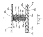
- Figure 6 is a partial cross-sectional view of the rotary connector of Figure 1 shown along viewing lines VI-VI thereof.
- Connector 10 has particular applicability for use in an automobile steering wheel whereby electrical switches, or electronic circuit boxes, housed in the steering wheel may be electrically connected through cables 12 to electrical components contained in the automobile engine compartment and elsewhere in the automobile through conductors 14 disposed in a connector 15 having a layer of over-molded insulation. It should be appreciated that while electrical conductors 14 remain stationary with respect to the automobile steering column, cables 12 rotate with the turning of the automobile steering wheel.
- Such a rotary connector 10 may be used for establishing electrical connection to a deployable air bag mounted in the steering wheel, an audio system, automobile lights, heating devices in the steering wheel and any other automobile accessories that are electrically and/or electronically controlled.
- the structural components of the connector comprise a first housing or rotor 16, a second housing or stator 18 and a cable holder 20.
- each of the rotor 16, stator 18 and cable holder 20 are particularly formed to be generally circular, although it can be appreciated that other shapes of these components may be used.
- the rotor 16 includes a downwardly extending lip 16a which supports one end of a flat cable ( Figure 4) that is connected to electrical cables 12 through a connector 22 supported on the upper surface of rotor 16.
- the rotor 16 includes a plurality of openings 16b through which a screwdriver, for example, may be used to attach the stator 18 to a steering column by screws 24.
- Suitable threaded locking bushings 26 may be used in conjunction with screws 24 for fixing the stator 18 to the steering column.
- the downwardly extending lip 16a of the rotor 16 is rotatably movable with respect to the stator 18.
- the stator 18 In use in the automobile, the stator 18 is typically secured to the steering column in a fixed position while the rotor 16 is rotatably secured to the steering wheel for turning movement therewith.
- Cable holder 20 includes an outer wall 20a and inner concentric wall 20b spaced radially within the outer wall 20a. Located around the cable holder 20 at approximately 90° intervals and between the outer wall 20a in the inner wall 20b are four arcuate connecting walls 20c. It should be appreciated that while four such arcuate connecting walls 20c are provided in this particular arrangement, different numbers of such walls may be suitably used. Cable holder 20 further includes an interior opening 20d for receipt therethrough of the downwardly extending rotor lip portion 16a.
- a flat multiconductor cable 28 is supported by the cable holder 20 as shown in Figure 4.
- One end of the flat cable 28 is electrically connected to the cables 12 while the other end of the flat cable is connected to the conductors 14.
- a reversal or loop back of the cable 28 is provided by the arcuate connecting walls 20c in the cable holder 20.
- the cable holder 20 includes a bottom wall 20e supporting a plurality of wells 30, each of which contains a spring biased spacer 32 as will be described. In the particular arrangement shown, there are three spring biased spacers 32 provided, although more or less spacers 32 may be used.
- the stator 18 includes an outer wall 18a, an inner wall 18b concentric with outer wall 18a and spaced radially inwardly therefrom, and a bottom wall 18c.
- the cable holder 20 with the flat electrical cable 28 therein is supported by the stator 18 for rotatable movement therebetween.
- the cable holder 20 includes an exit opening 20f through the outer wall 20a thereof and each of the arcuate connecting walls 20c.
- the inner stator wall 18b has an opening 18d through which the cable exiting the cable holder 20 is received for ultimate connection to the conductors 14.
- the stator 18 further includes an interior opening 18d for retentive receipt of the downwardly extending lip 16a of the rotor 16 by which the rotor 16 is movably secured to the stator 18.
- stator 18 In assembly, the stator 18 is affixed to the automobile steering column and will remain stationary upon rotation of the steering wheel.
- the rotor 16 rotates with the turning of the steering wheel.
- each spacer 32 comprises a generally cylindrical body 32a, an interior enclosure 32b, a closed upper end 32c and an open lower end 32d communicating with the enclosure 32b.
- a flange 32e projects radially outwardly from the exterior surface of the body 32a.
- the upper surface of flange 32e is generally flat while the lower surface of the flange 32e is tapered at an oblique angle.
- Flange 32e may also be used to assist during product handling.
- the cylindrical body 32a includes a substantially flat wall 32f on an exterior surface thereof and at least one longitudinally extending slot 32g extending through the wall of the cylindrical body 32a and communicating with the interior enclosure 32b.
- the wells 30 are each supported on the floor 20e of the cable holder 20, each well 30 having a generally cylindrical cavity 30a of configuration complementary to the configuration of cylindrical body 32a for receipt of the spacers 32 respectively therein.
- Each well 30 includes an inner shoulder 30b for engagement with the upper surface of spacer flange 32e.
- Each well 30 is preferably configured to have an inner flat surface 30c formed in cavity 30a for complementary engagement with the flat surface 32f on the spacer 32a when the spacer is received within the well 30, to prevent relative rotational movement of the spacers 32 within the wells 30.
- a generally cylindrical, elongate post 34 Supported on the bottom wall 20e of the cable holder 20 and projecting upwardly within the cavity 30a of each well 30, is a generally cylindrical, elongate post 34. Situated around post 34 and disposed within the interior enclosure 32b of each spacer 32 is a spring 36, preferably in helical form, although other spring configurations may be used. Helical spring 36 is of length to extend from engagement with the upper closed end 32c of the spacer 32 to engagement with the bottom wall 20e of the cable holder 20.
- the spring biased spacers 32 are assembled as follows.
- the helical spring 36 is placed over the post 34 onto the floor 20e of the cable holder 20.
- the spacer 32 is inserted into the well cavity 30a such that the bottom tapered surface of the flange 32e exerts an inward radial force on the cylindrical body 32a.
- the cylindrical body 32a will radially compress inwardly allowing the flange 32e to be received within the well cavity 30a.
- the flat surface of the spacer flange 32e will engage the well shoulder 30b thereby captivating the spacer 32 in the well 30.
- the helical spring 36 Upon captivation, the helical spring 36 will be axially compressed between the upper end 32c of the spacer 32 and the bottom wall 20e of the cable holder 20. An axial portion 32h of the spacer 32 will project upwardly beyond the upper end of the well 30 so that upon application of a downward force F ( Figure 6) placed against the spacer closed end 32c, the helical spring 36 may be further biased, with the cylindrical spacer body 32 movable thereagainst.
- the operation of the spring biased spacers 32 is as follows.
- the movable rotor 16 engages the upper flat end 32c of each spacer 32 thereby exerting force F downwardly onto each spacer 32.
- the cable holder Under the downward bias of the spring 36 against the bottom wall 20e of the cable holder 20, the cable holder is urged into engagement with the bottom wall 18c of the stator 18 and under such bias of spring 36, the cable holder 20 is maintained in contact therewith during movement of the cable holder 20 with respect to both the stator 28 and the rotor 16.
- axial movement of the cable holder 20 with respect to both the stator 18 and the rotor 16 is prevented and vibratory noise resulting therefrom is eliminated.
- the spacers 32 are made preferably of a material having a substantially low coefficient of friction, such as syndiadactic polystyrene (SPS) and polytetrafluoroethylene.
- SPS syndiadactic polystyrene
- the bottom surface of rotor 16 may also be polished so as to provide a relatively smooth sliding contact with the upper flat end 32 of the spacers 32.
- the upper spacer end 32e may also be formed of other shapes, such as arcuate, so as to facilitate smooth movement with the bottom surface of rotor 16.
- the lower surface 20f ( Figure 6) of the bottom wall 20e of the cable holder 20 may be formed to have polished buttons 20g spaced radially thereabout to provide substantially point contact engagement with the bottom wall 18c of the stator 18 so as further minimize friction and the resulting vibration and noise.
Landscapes
- Engineering & Computer Science (AREA)
- Mechanical Engineering (AREA)
- Steering Controls (AREA)
- Electric Cable Arrangement Between Relatively Moving Parts (AREA)
- Coupling Device And Connection With Printed Circuit (AREA)
Priority Applications (1)
| Application Number | Priority Date | Filing Date | Title |
|---|---|---|---|
| EP02006986A EP1247697A3 (de) | 2001-04-03 | 2002-03-27 | Drehschalter |
Applications Claiming Priority (3)
| Application Number | Priority Date | Filing Date | Title |
|---|---|---|---|
| EP01108348 | 2001-04-03 | ||
| EP01108348 | 2001-04-03 | ||
| EP02006986A EP1247697A3 (de) | 2001-04-03 | 2002-03-27 | Drehschalter |
Publications (2)
| Publication Number | Publication Date |
|---|---|
| EP1247697A2 true EP1247697A2 (de) | 2002-10-09 |
| EP1247697A3 EP1247697A3 (de) | 2003-10-22 |
Family
ID=26076528
Family Applications (1)
| Application Number | Title | Priority Date | Filing Date |
|---|---|---|---|
| EP02006986A Withdrawn EP1247697A3 (de) | 2001-04-03 | 2002-03-27 | Drehschalter |
Country Status (1)
| Country | Link |
|---|---|
| EP (1) | EP1247697A3 (de) |
Cited By (5)
| Publication number | Priority date | Publication date | Assignee | Title |
|---|---|---|---|---|
| EP2555346A4 (de) * | 2010-03-30 | 2014-04-30 | Furukawa Electric Co Ltd | Drehbare konnektorvorrichtung |
| CN110036541A (zh) * | 2016-12-06 | 2019-07-19 | 古河电气工业株式会社 | 缓冲部件和旋转连接器装置 |
| EP3582353A1 (de) * | 2018-06-15 | 2019-12-18 | Yazaki Corporation | Flachkabelaufrollvorrichtung |
| CN111820814A (zh) * | 2019-04-23 | 2020-10-27 | 博西华电器(江苏)有限公司 | 刷头及清洁设备 |
| EP4382366A1 (de) * | 2022-12-08 | 2024-06-12 | Nexans | Uhrfederanordnung |
Citations (4)
| Publication number | Priority date | Publication date | Assignee | Title |
|---|---|---|---|---|
| US3763445A (en) | 1971-03-08 | 1973-10-02 | Tektronix Inc | Variable length transmission line |
| US5529505A (en) | 1993-05-31 | 1996-06-25 | Alps Electric Co., Ltd. | Clock spring connector |
| US5637005A (en) | 1993-05-31 | 1997-06-10 | Alps Electric Co., Ltd. | Clock spring connector |
| US5882216A (en) | 1996-07-15 | 1999-03-16 | Alps Electric Co., Ltd. | Rotary connector |
Family Cites Families (3)
| Publication number | Priority date | Publication date | Assignee | Title |
|---|---|---|---|---|
| JP2752529B2 (ja) * | 1991-05-09 | 1998-05-18 | アルプス電気株式会社 | ケーブルリール |
| JP2921734B2 (ja) * | 1994-09-02 | 1999-07-19 | 矢崎総業株式会社 | ハンドルとステアリングコラム間の電気的接続装置 |
| JP3713910B2 (ja) * | 1997-07-11 | 2005-11-09 | 松下電器産業株式会社 | 回転コネクタ |
-
2002
- 2002-03-27 EP EP02006986A patent/EP1247697A3/de not_active Withdrawn
Patent Citations (4)
| Publication number | Priority date | Publication date | Assignee | Title |
|---|---|---|---|---|
| US3763445A (en) | 1971-03-08 | 1973-10-02 | Tektronix Inc | Variable length transmission line |
| US5529505A (en) | 1993-05-31 | 1996-06-25 | Alps Electric Co., Ltd. | Clock spring connector |
| US5637005A (en) | 1993-05-31 | 1997-06-10 | Alps Electric Co., Ltd. | Clock spring connector |
| US5882216A (en) | 1996-07-15 | 1999-03-16 | Alps Electric Co., Ltd. | Rotary connector |
Cited By (9)
| Publication number | Priority date | Publication date | Assignee | Title |
|---|---|---|---|---|
| EP2555346A4 (de) * | 2010-03-30 | 2014-04-30 | Furukawa Electric Co Ltd | Drehbare konnektorvorrichtung |
| CN110036541A (zh) * | 2016-12-06 | 2019-07-19 | 古河电气工业株式会社 | 缓冲部件和旋转连接器装置 |
| EP3547467A4 (de) * | 2016-12-06 | 2019-12-18 | Furukawa Electric Co., Ltd. | Dämpfungselement und drehverbindervorrichtung |
| CN110036541B (zh) * | 2016-12-06 | 2021-04-13 | 古河电气工业株式会社 | 缓冲部件和旋转连接器装置 |
| US11692609B2 (en) | 2016-12-06 | 2023-07-04 | Furukawa Electric Co., Ltd. | Damping member and rotary connector device |
| EP3582353A1 (de) * | 2018-06-15 | 2019-12-18 | Yazaki Corporation | Flachkabelaufrollvorrichtung |
| CN111820814A (zh) * | 2019-04-23 | 2020-10-27 | 博西华电器(江苏)有限公司 | 刷头及清洁设备 |
| EP4382366A1 (de) * | 2022-12-08 | 2024-06-12 | Nexans | Uhrfederanordnung |
| US12592530B2 (en) | 2022-12-08 | 2026-03-31 | Nexans | Clock spring assembly |
Also Published As
| Publication number | Publication date |
|---|---|
| EP1247697A3 (de) | 2003-10-22 |
Similar Documents
| Publication | Publication Date | Title |
|---|---|---|
| US6328243B1 (en) | Reel device for wire harness | |
| EP1650838B1 (de) | Drehverbinder | |
| US5246377A (en) | Apparatus for electrically connecting a rotary connector and a wiring harness | |
| EP1247697A2 (de) | Drehschalter | |
| JP3522148B2 (ja) | 回転コネクタ | |
| US5707023A (en) | Apparatus for establishing electrical connection between rotor and fixed member | |
| KR100454401B1 (ko) | 회전커넥터 | |
| JP3393762B2 (ja) | 車載用回転コネクタ | |
| US20030008540A1 (en) | Rotary loop back connector | |
| JP3461468B2 (ja) | ワイヤハーネス巻取り装置 | |
| JP4355229B2 (ja) | 回転コネクタ | |
| KR101896060B1 (ko) | 자동차 조향장치의 전자제어장치 | |
| KR100318040B1 (ko) | 회전커넥터의설치구조와회전커넥터및이를사용한스티어링유닛 | |
| JP3273540B2 (ja) | 回転コネクタの取付構造 | |
| JP3569465B2 (ja) | ワイヤハーネス巻取り装置 | |
| US5690500A (en) | Electrical connecting device for connecting rotor with stator through cable | |
| JPH08162241A (ja) | 固定体と回転体との電気的接続装置 | |
| EP0880205B1 (de) | Montagestruktur für Drehverbinder | |
| JP3709998B2 (ja) | 回転コネクタ | |
| JPH1074573A (ja) | 回転コネクタ | |
| US7413454B2 (en) | Apparatus for signal transmission between terminals | |
| JP2006216370A (ja) | 回転コネクタ | |
| JP3416411B2 (ja) | 回転コネクタの取付け構造 | |
| JPH0649082Y2 (ja) | 小型モータのブラシ保持装置 | |
| JP2000306649A (ja) | 回転コネクタ |
Legal Events
| Date | Code | Title | Description |
|---|---|---|---|
| PUAI | Public reference made under article 153(3) epc to a published international application that has entered the european phase |
Free format text: ORIGINAL CODE: 0009012 |
|
| AK | Designated contracting states |
Kind code of ref document: A2 Designated state(s): AT BE CH CY DE DK ES FI FR GB GR IE IT LI LU MC NL PT SE TR |
|
| AX | Request for extension of the european patent |
Free format text: AL;LT;LV;MK;RO;SI |
|
| PUAL | Search report despatched |
Free format text: ORIGINAL CODE: 0009013 |
|
| AK | Designated contracting states |
Kind code of ref document: A3 Designated state(s): AT BE CH CY DE DK ES FI FR GB GR IE IT LI LU MC NL PT SE TR |
|
| AX | Request for extension of the european patent |
Extension state: AL LT LV MK RO SI |
|
| 17P | Request for examination filed |
Effective date: 20031006 |
|
| AKX | Designation fees paid |
Designated state(s): AT BE CH CY DE DK ES FI FR GB GR IE IT LI LU MC NL PT SE TR |
|
| 17Q | First examination report despatched |
Effective date: 20041022 |
|
| STAA | Information on the status of an ep patent application or granted ep patent |
Free format text: STATUS: THE APPLICATION IS DEEMED TO BE WITHDRAWN |
|
| 18D | Application deemed to be withdrawn |
Effective date: 20050503 |