EP1247894A2 - Presse et caisse d'aspiration - Google Patents
Presse et caisse d'aspiration Download PDFInfo
- Publication number
- EP1247894A2 EP1247894A2 EP02007027A EP02007027A EP1247894A2 EP 1247894 A2 EP1247894 A2 EP 1247894A2 EP 02007027 A EP02007027 A EP 02007027A EP 02007027 A EP02007027 A EP 02007027A EP 1247894 A2 EP1247894 A2 EP 1247894A2
- Authority
- EP
- European Patent Office
- Prior art keywords
- suction
- fibrous web
- press
- suction element
- stationary
- Prior art date
- Legal status (The legal status is an assumption and is not a legal conclusion. Google has not performed a legal analysis and makes no representation as to the accuracy of the status listed.)
- Granted
Links
Images

Classifications
-
- D—TEXTILES; PAPER
- D21—PAPER-MAKING; PRODUCTION OF CELLULOSE
- D21F—PAPER-MAKING MACHINES; METHODS OF PRODUCING PAPER THEREON
- D21F3/00—Press section of machines for making continuous webs of paper
- D21F3/02—Wet presses
- D21F3/04—Arrangements thereof
- D21F3/045—Arrangements thereof including at least one extended press nip
-
- D—TEXTILES; PAPER
- D21—PAPER-MAKING; PRODUCTION OF CELLULOSE
- D21F—PAPER-MAKING MACHINES; METHODS OF PRODUCING PAPER THEREON
- D21F3/00—Press section of machines for making continuous webs of paper
- D21F3/02—Wet presses
- D21F3/0272—Wet presses in combination with suction or blowing devices
Definitions
- the invention relates to a press arrangement for draining a paper, cardboard, tissue or other Fibrous web in a machine for producing the same with at least a press nip formed by two press rolls through which next a press felt runs on both sides of the fibrous web.
- a second Aspect relates to a stationary suction element which in the preamble of Claim 11 Art.
- a press arrangement of the type mentioned is, for example, in the US 5 951 821.
- Suction elements of the type mentioned result, for example, from the publications US 5 885 421, DE-C-41 02 065, EP-A-0 405 154, DE-C-195 11 988 and DE-A-27 16 583.
- the first aspect of the invention teaches in particular high web speeds leading away the upper press felt from problems with the fibrous web after the press nip. Is critical especially the edge area of the fibrous web. The edge often comes loose not immediately from the upper press felt, so that it plucked so-called comes. As a result, there are tears or even tears in the fibrous web not uncommon.
- the object was achieved in that after Press nip both press felts together with the fiber web a guide roller partially loop around the lower press felt and form one with the suction press in contact with the lower press felt, whereby the upper press felt in the area of the suction box from the fibrous web is led away.
- the deflection on the guide roller makes it easy Detachment of the upper press felt from the fibrous web - especially if the guide roller is vacuumed. The vacuum coming from the suction box then enables the upper press felt to be easily removed the fibrous web.
- the negative pressure of the guide roller and the suction box acts through the through the lower press felt and thus increases the adhesion of the fibrous web on the lower press felt.
- the upper press felt is advantageous already in the beginning of the suction box from the fibrous web led away.
- the contact surface should of the suction box at least in one, preferably at the beginning Section be convexly curved towards the lower press felt. It can however, it may also be advantageous if all or at least the majority Part of the contact surface of the suction box is convex to the lower one Press felt is curved.
- a special configuration results if the contact surface of the suction box in a preferably at the beginning lying section has a stronger, convex curvature than in the remaining part.
- the device according to the invention allows the upper press felt in Lead area of the first suction slot away from the fibrous web, see above that in the further course of the suction box the adhesion of the fibrous web can be increased on the lower press felt.
- the suction box should be in the area of the edges of the fibrous web each have a separate vacuum zone with increased negative pressure.
- the invention relates to a stationary suction element for sucking up a paper, cardboard, tissue or other Fibrous web on an air-permeable, endlessly running belt Machine for the production and / or finishing of the fibrous web, wherein the tape slides over a contact surface of the suction element and the Contact surface has several suction openings and use.
- suction elements are also known as suction boxes with a substantially flat contact surface.
- the Adhesion of the fibrous web often used vacuumed rollers. Due to the limited open surface (suction openings) of a vacuumed roller, which is between 20 and 60%, the fibrous web is mainly at high speeds insufficiently fixed to the belt, making it can come off the web and flutter.
- Another object of the invention is therefore with as little as possible Effort, the adhesion of the fibrous web to the belt during a belt deflection to improve.
- this object has been achieved in that the contact surface runs convexly curved in the direction of web travel.
- the curved one The contact surface is immersed in the belt and enables such a relatively long, vacuumed route.
- the fibrous web adheres very well to the belt itself at high speeds and despite the belt deflection. This also applies to the edges of the fibrous web.
- Suction elements whose contact surface in the web running direction are particularly suitable is curved in the shape of a sector of a circle, the radius of curvature are in the range of 0.2 to 10 m, preferably between 0.4 and 3 m should. However, other forms of curvature are also possible.
- the suction openings should be designed as suction slots.
- suction slots are oblique to the web running direction run.
- the oblique arrangement looks like a suction the tape into the suction slots.
- suction slots it is also possible for the suction slots to be approximately transverse to the web running direction run.
- the suction element several, preferably transversely to the web running direction extending and arranged side by side in the web running direction Has suction zones, at least that of the suction openings outgoing vacuum of each suction zone is independently adjustable. there it is often sufficient if the suction element has two suction zones. For certain application it can limit energy for negative pressure generation as well as the volume caused by the air flow, be advantageous if the suction element at least, preferably has exactly three suction zones.
- Suction opening outgoing negative pressure is separately adjustable. This applies especially if at least one, preferably all Suction zones are formed by one suction opening each. However, can also the suction openings of a suction zone, if it has several, individually be adjustable.
- the desired extension of the suction zones in the direction of web travel may require at least one, preferably all Suction zones are formed by several suction openings, the Suction openings of a suction zone with each other via a suction chamber are connected and the vacuum in the suction chambers separately is adjustable.
- the level of the negative pressure of each suction zone cannot only manually adjustable, but also independently controllable become.
- the controllability allows adjustments to the web speed, the type of fibrous web, its weight, moisture content, etc.
- the suction element can preferably be humidified at the beginning assigned to moisten the contact surface. Suitable for this purpose are, for example, transverse to the web running direction Sprays. For versions with many suction openings there is also one Humidification possible from the inside of the suction element.
- the stationary suction element is particularly suitable for use with which the fibrous web in front of the suction element from both sides one Band guided and that with respect to the suction element outer band in Area of the suction element is guided away from the fibrous web.
- the Curvature of the contact surface allows a relatively large opening angle between the bands, what the ventilation of the gusset improved. As a result, the risk of edge fluttering decreases Fibrous web.
- the opening angle should preferably be greater than 10 ° his.
- the outer band When using the suction element, the outer band should be in the direction of web travel viewed in the middle of the contact area of the fibrous web are led away. It is particularly advantageous if the outer band in the area of the second suction zone from the fibrous web is led away, the suction element preferably three suction zones having.
- the first suction zone serves to pre-fix the fibrous web on the belt, the second of fixing the fibrous web during the Removal of the outer ligament and the third fixation. All Suction zones have different requirements due to their function to the level of negative pressure, so that via the separate control the level of negative pressure, the noise and the energy for Vacuum generation can be minimized.
- Suitable applications arise where at least the tape running between the fibrous web and the suction element as Press felt of a press section designed for dewatering the fibrous web is.
- the use is particularly advantageous where the tapes with the fibrous web from a press nip of the press section to Arrive suction element, wherein the press nip preferably extends should be executed.
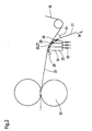
- Figure 1 shows a cross section of an exemplary embodiment a press assembly according to the first aspect of the invention.
- the fibrous web 1 runs through on both sides with a press felt 4.5 a press nip formed by two press rolls 2, 3. While the lower one Press roll 3 is cylindrical, the upper press roll 2 a flexible roll shell, which forms an extended press nip runs over a pressure shoe with a concave pressure surface. Naturally is a reversal of this press roll arrangement, that is upper cylindrical press roll 3 also possible.
- Press felts 4, 5 take this from the fibrous web 1 in the press nip pressed water. That via the press felts 4, 5 to the press rolls 2, 3 Any water that enters is thrown off by these after the press nip and taken up by suitable, known water collecting device 12.
- the fibrous web 1 runs together with both Press felts 4, 5 via a suction guide roller 6 of the lower press felt 5.
- This guide roller 6 has a perforated roller shell, the interior is connected to a vacuum source. This negative pressure works through the lower press felt 5 onto the fibrous web 1 and thus reinforced the adhesion of the fibrous web 1 to the lower press felt 5.
- Suction box 7 has a convex curve towards the lower press felt 5 Contact area.
- the delimitation of that associated with a vacuum source Interior of the suction box 7 opposite the lower press felt 5 is by the formation of several, transverse to the web running direction 8th extending suction slots 9 guaranteed in the contact surface.
- the negative pressure of the suction box 7 increases Adhesion of the entire fibrous web 1 to the lower press felt 5, so that already in the area of the first suction slot 9 of the suction box 7 the upper one Press felt 4 can be guided away from the fibrous web 1.
- the fibrous web 1 is then attached to a belt 10, for example a Hand over dryer fabric to a subsequent dryer section of the paper machine, which is supported by a suction guide roller 11.
- Figure 2 shows a schematic cross section of an exemplary Embodiment of a suction element 23 according to the second aspect the invention.
- the fibrous web 21 runs together with a belt on both sides 22, 30 an extended press nip formed by two press rollers 32. This serves to dewater the fibrous web 21, the belts 22, 30 designed as water-absorbing and air-permeable press felts are.
- the press nip is part of a press section of a paper machine for manufacture the fibrous web 21.
- the fibrous web 21 is removed from the press nip by both belts 22, 30 led to the suction element 23.
- the middle area of the suction element 23 is that, with respect to the suction element 23 outer band 30 from the fibrous web 21 led away.
- the inner band 22 guides the fibrous web 21 to a subsequent unit, the fibrous web 21 for example from a press felt of a subsequent press nip or one Dryer screen of a following dryer section can be taken over.
- the suction element 23 has a contact area curved in the shape of a sector of a circle 24 over which the inner band 22 slides.
- the radius of curvature this convex curvature is approximately 1 m.
- the suction element 23 has three suction zones 27, each of which has a suction opening 25 in the form of a suction slot running transversely to the web running direction 26 are formed in the contact surface 24.
- the suction openings 25 are each connected to a vacuum source via a suction chamber, the level of vacuum of each suction chamber 34 independent is controllable via a valve 33.
- the negative pressure emanating from the suction openings 25 can thus be applied to the local requirements are adjusted and minimized in height what not only saves energy, but also reduces the noise of the air flow.
- first suction opening 25 or suction zone 27 serves the Adhesion of the fibrous web 21 to the inner band 22 to increase through the second suction zone 27 a lifting of the fibrous web 21, in particular of its edges, from the inner band 22 during the removal of the outer band 30 can be prevented. Therefore requires the second suction zones 27 an increased negative pressure.
- the last suction zone 27 in the direction of web travel 26 is only intended to again Strengthen the adhesion of the fibrous web 21 to the inner band 22 and requires it therefore usually a lower negative pressure.
- the opening angle is 31 between Fibrous web 21 and the outer band 30 about 20 °.
- the contact surface 24 of the suction element 23 is essentially of Ledges 29 extending transversely to the web running direction 26 are formed. This Last 29 are adapted to the tape run and limit the individual Suction openings 25, that is, the suction slots.
- the strips 29 have a ceramic layer on the surface guiding the strip 22.
Landscapes
- Paper (AREA)
- Massaging Devices (AREA)
- Press Drives And Press Lines (AREA)
Applications Claiming Priority (4)
| Application Number | Priority Date | Filing Date | Title |
|---|---|---|---|
| DE10116364 | 2001-04-02 | ||
| DE20106685U DE20106685U1 (de) | 2001-04-02 | 2001-04-02 | Pressanordnung |
| DE20106685U | 2001-04-02 | ||
| DE2001116364 DE10116364A1 (de) | 2001-04-02 | 2001-04-02 | Saugelement |
Publications (3)
| Publication Number | Publication Date |
|---|---|
| EP1247894A2 true EP1247894A2 (fr) | 2002-10-09 |
| EP1247894A3 EP1247894A3 (fr) | 2003-01-02 |
| EP1247894B1 EP1247894B1 (fr) | 2006-05-17 |
Family
ID=26008983
Family Applications (1)
| Application Number | Title | Priority Date | Filing Date |
|---|---|---|---|
| EP02007027A Expired - Lifetime EP1247894B1 (fr) | 2001-04-02 | 2002-03-27 | Presse et caisse d'aspiration |
Country Status (3)
| Country | Link |
|---|---|
| EP (1) | EP1247894B1 (fr) |
| AT (1) | ATE326576T1 (fr) |
| DE (1) | DE50206776D1 (fr) |
Cited By (2)
| Publication number | Priority date | Publication date | Assignee | Title |
|---|---|---|---|---|
| EP1505206A1 (fr) * | 2003-08-07 | 2005-02-09 | Voith Paper Patent GmbH | Souffleur ou aspirateur pour machine à papier |
| EP1884589A1 (fr) * | 2006-08-04 | 2008-02-06 | Voith Patent GmbH | Dispositif d'aspiration stable, utilisation et machine destinée à la fabrication de bandes de matière fibreuse dotées d'un tel dispositif d'aspiration |
Family Cites Families (4)
| Publication number | Priority date | Publication date | Assignee | Title |
|---|---|---|---|---|
| CA1285411C (fr) * | 1986-06-19 | 1991-07-02 | Gerald E. Eldridge | Dispositif coucheur fixe sur machine a papier |
| DE4002304A1 (de) * | 1990-01-26 | 1991-08-14 | Escher Wyss Gmbh | Former in einer papiermaschine |
| US5328569A (en) * | 1992-06-26 | 1994-07-12 | Beloit Technologies, Inc. | Curved suction box apparatus in a papermaking machine press section |
| FI105706B (fi) * | 1999-04-29 | 2000-09-29 | Valmet Corp | Sovitelma paperi- tai kartonkikoneen rainan kuumennuslaitteen yhteydessä |
-
2002
- 2002-03-27 EP EP02007027A patent/EP1247894B1/fr not_active Expired - Lifetime
- 2002-03-27 AT AT02007027T patent/ATE326576T1/de active
- 2002-03-27 DE DE50206776T patent/DE50206776D1/de not_active Expired - Lifetime
Cited By (2)
| Publication number | Priority date | Publication date | Assignee | Title |
|---|---|---|---|---|
| EP1505206A1 (fr) * | 2003-08-07 | 2005-02-09 | Voith Paper Patent GmbH | Souffleur ou aspirateur pour machine à papier |
| EP1884589A1 (fr) * | 2006-08-04 | 2008-02-06 | Voith Patent GmbH | Dispositif d'aspiration stable, utilisation et machine destinée à la fabrication de bandes de matière fibreuse dotées d'un tel dispositif d'aspiration |
Also Published As
| Publication number | Publication date |
|---|---|
| DE50206776D1 (de) | 2006-06-22 |
| EP1247894B1 (fr) | 2006-05-17 |
| EP1247894A3 (fr) | 2003-01-02 |
| ATE326576T1 (de) | 2006-06-15 |
Similar Documents
| Publication | Publication Date | Title |
|---|---|---|
| DE3328162A1 (de) | Papiermaschine | |
| DE19983540B4 (de) | Verfahren und Vorrichtung bei einer Papiermaschine zum Übertragen einer Bahn von einer Bahnbildungspartie zu einer Pressenpartie | |
| EP0468005B1 (fr) | Dispositif de transfert d'une bande de la zone de pressage vers la zone de sechage d'une machine a papier | |
| EP0949375B9 (fr) | Arrangement pour transférer une bande fibreuse | |
| DE102008043294A1 (de) | Verfahren und Vorrichtung zum Überführen der Papierbahn von einem Stützgewebe | |
| DE102011087094A1 (de) | Verfahren zur Überführung einer Materialbahn von einer Trockenanordnung zu einer nachgeordneten Funktionseinheit und Trockenvorrichtung | |
| EP0735182B1 (fr) | Section de presse | |
| EP1048780B1 (fr) | Section de pressage | |
| DE4035985B4 (de) | Absaugverfahren und Absaugvorrichtung in einer Papiermaschine | |
| EP3622112A1 (fr) | Dispositif et procédé de fabrication d'une bande de matière fibreuse | |
| EP1247894A2 (fr) | Presse et caisse d'aspiration | |
| EP0954634B1 (fr) | Systeme de presse | |
| DE3222428A1 (de) | Doppelsieb-papiermaschine | |
| DE102007021879A1 (de) | Pressenanordnung und Maschine zur Herstellung einer Faserstoffbahn | |
| DE10116364A1 (de) | Saugelement | |
| DE102017110032A1 (de) | Vorrichtung und Verfahren zur Herstellung einer Faserstoffbahn | |
| DE4335024C2 (de) | Pressenpartie einer Papiermaschine und Überführeinrichtung | |
| DE112009000676T5 (de) | Faserbahnmaschinenkonzept, Faserbahnmaschine und Verfahren zum Herstellen einer Faserbahn | |
| DE102017111869A1 (de) | Vorrichtung und Verfahren zur Herstellung einer Faserstoffbahn | |
| EP1281807A2 (fr) | Machine pour la fabrication d'une bande fibreuse | |
| DE20122815U1 (de) | Saugelement | |
| EP1777340B1 (fr) | Agencement de presse | |
| DE10333139A1 (de) | Pressenpartie | |
| DE20106685U1 (de) | Pressanordnung | |
| DE4315887C2 (de) | Zweizug-Trockenpartie |
Legal Events
| Date | Code | Title | Description |
|---|---|---|---|
| PUAI | Public reference made under article 153(3) epc to a published international application that has entered the european phase |
Free format text: ORIGINAL CODE: 0009012 |
|
| 17P | Request for examination filed |
Effective date: 20020327 |
|
| AK | Designated contracting states |
Kind code of ref document: A2 Designated state(s): AT BE CH CY DE DK ES FI FR GB GR IE IT LI LU MC NL PT SE TR |
|
| AX | Request for extension of the european patent |
Free format text: AL;LT;LV;MK;RO;SI |
|
| PUAL | Search report despatched |
Free format text: ORIGINAL CODE: 0009013 |
|
| AK | Designated contracting states |
Kind code of ref document: A3 Designated state(s): AT BE CH CY DE DK ES FI FR GB GR IE IT LI LU MC NL PT SE TR |
|
| AX | Request for extension of the european patent |
Free format text: AL;LT;LV;MK;RO;SI |
|
| AKX | Designation fees paid |
Designated state(s): AT DE FI IT SE |
|
| 17Q | First examination report despatched |
Effective date: 20040803 |
|
| GRAP | Despatch of communication of intention to grant a patent |
Free format text: ORIGINAL CODE: EPIDOSNIGR1 |
|
| GRAS | Grant fee paid |
Free format text: ORIGINAL CODE: EPIDOSNIGR3 |
|
| GRAA | (expected) grant |
Free format text: ORIGINAL CODE: 0009210 |
|
| AK | Designated contracting states |
Kind code of ref document: B1 Designated state(s): AT DE FI IT SE |
|
| PG25 | Lapsed in a contracting state [announced via postgrant information from national office to epo] |
Ref country code: IT Free format text: LAPSE BECAUSE OF FAILURE TO SUBMIT A TRANSLATION OF THE DESCRIPTION OR TO PAY THE FEE WITHIN THE PRESCRIBED TIME-LIMIT;WARNING: LAPSES OF ITALIAN PATENTS WITH EFFECTIVE DATE BEFORE 2007 MAY HAVE OCCURRED AT ANY TIME BEFORE 2007. THE CORRECT EFFECTIVE DATE MAY BE DIFFERENT FROM THE ONE RECORDED. Effective date: 20060517 |
|
| REF | Corresponds to: |
Ref document number: 50206776 Country of ref document: DE Date of ref document: 20060622 Kind code of ref document: P |
|
| REG | Reference to a national code |
Ref country code: SE Ref legal event code: TRGR |
|
| RAP2 | Party data changed (patent owner data changed or rights of a patent transferred) |
Owner name: VOITH PATENT GMBH |
|
| PLBE | No opposition filed within time limit |
Free format text: ORIGINAL CODE: 0009261 |
|
| STAA | Information on the status of an ep patent application or granted ep patent |
Free format text: STATUS: NO OPPOSITION FILED WITHIN TIME LIMIT |
|
| 26N | No opposition filed |
Effective date: 20070220 |
|
| PGFP | Annual fee paid to national office [announced via postgrant information from national office to epo] |
Ref country code: IT Payment date: 20090321 Year of fee payment: 8 Ref country code: SE Payment date: 20090312 Year of fee payment: 8 |
|
| EUG | Se: european patent has lapsed | ||
| PG25 | Lapsed in a contracting state [announced via postgrant information from national office to epo] |
Ref country code: IT Free format text: LAPSE BECAUSE OF NON-PAYMENT OF DUE FEES Effective date: 20100327 |
|
| PG25 | Lapsed in a contracting state [announced via postgrant information from national office to epo] |
Ref country code: SE Free format text: LAPSE BECAUSE OF NON-PAYMENT OF DUE FEES Effective date: 20100328 |
|
| PGFP | Annual fee paid to national office [announced via postgrant information from national office to epo] |
Ref country code: DE Payment date: 20200320 Year of fee payment: 19 Ref country code: FI Payment date: 20200320 Year of fee payment: 19 Ref country code: AT Payment date: 20200320 Year of fee payment: 19 |
|
| REG | Reference to a national code |
Ref country code: DE Ref legal event code: R119 Ref document number: 50206776 Country of ref document: DE |
|
| REG | Reference to a national code |
Ref country code: FI Ref legal event code: MAE |
|
| PG25 | Lapsed in a contracting state [announced via postgrant information from national office to epo] |
Ref country code: FI Free format text: LAPSE BECAUSE OF NON-PAYMENT OF DUE FEES Effective date: 20210327 |
|
| REG | Reference to a national code |
Ref country code: AT Ref legal event code: MM01 Ref document number: 326576 Country of ref document: AT Kind code of ref document: T Effective date: 20210327 |
|
| PG25 | Lapsed in a contracting state [announced via postgrant information from national office to epo] |
Ref country code: DE Free format text: LAPSE BECAUSE OF NON-PAYMENT OF DUE FEES Effective date: 20211001 Ref country code: AT Free format text: LAPSE BECAUSE OF NON-PAYMENT OF DUE FEES Effective date: 20210327 |