EP1247905A2 - Durchgang durch Leitplanken von Fahrbahnen - Google Patents
Durchgang durch Leitplanken von Fahrbahnen Download PDFInfo
- Publication number
- EP1247905A2 EP1247905A2 EP02005619A EP02005619A EP1247905A2 EP 1247905 A2 EP1247905 A2 EP 1247905A2 EP 02005619 A EP02005619 A EP 02005619A EP 02005619 A EP02005619 A EP 02005619A EP 1247905 A2 EP1247905 A2 EP 1247905A2
- Authority
- EP
- European Patent Office
- Prior art keywords
- barrier
- transition
- elements
- barrier transition
- longitudinal elements
- Prior art date
- Legal status (The legal status is an assumption and is not a legal conclusion. Google has not performed a legal analysis and makes no representation as to the accuracy of the status listed.)
- Granted
Links
- 230000004888 barrier function Effects 0.000 title claims abstract description 91
- 230000007704 transition Effects 0.000 claims abstract description 49
- 230000008878 coupling Effects 0.000 claims abstract description 11
- 238000010168 coupling process Methods 0.000 claims abstract description 11
- 238000005859 coupling reaction Methods 0.000 claims abstract description 11
- 230000001681 protective effect Effects 0.000 claims description 10
- 230000000712 assembly Effects 0.000 claims description 6
- 238000000429 assembly Methods 0.000 claims description 6
- 239000002184 metal Substances 0.000 claims description 6
- 239000004567 concrete Substances 0.000 claims description 5
- 230000003116 impacting effect Effects 0.000 claims description 4
- 239000000463 material Substances 0.000 claims description 4
- 238000004873 anchoring Methods 0.000 claims description 3
- 229910000831 Steel Inorganic materials 0.000 claims 1
- 230000002146 bilateral effect Effects 0.000 claims 1
- 239000010959 steel Substances 0.000 claims 1
- 238000004381 surface treatment Methods 0.000 claims 1
- 238000010276 construction Methods 0.000 description 5
- 238000012423 maintenance Methods 0.000 description 4
- 239000000203 mixture Substances 0.000 description 2
- 206010039203 Road traffic accident Diseases 0.000 description 1
- 230000002860 competitive effect Effects 0.000 description 1
- 230000002939 deleterious effect Effects 0.000 description 1
- 238000005516 engineering process Methods 0.000 description 1
- 230000007246 mechanism Effects 0.000 description 1
- 239000007769 metal material Substances 0.000 description 1
- 238000000034 method Methods 0.000 description 1
- 238000012986 modification Methods 0.000 description 1
- 230000004048 modification Effects 0.000 description 1
- 239000011150 reinforced concrete Substances 0.000 description 1
- 230000002269 spontaneous effect Effects 0.000 description 1
Images


Classifications
-
- E—FIXED CONSTRUCTIONS
- E01—CONSTRUCTION OF ROADS, RAILWAYS, OR BRIDGES
- E01F—ADDITIONAL WORK, SUCH AS EQUIPPING ROADS OR THE CONSTRUCTION OF PLATFORMS, HELICOPTER LANDING STAGES, SIGNS, SNOW FENCES, OR THE LIKE
- E01F15/00—Safety arrangements for slowing, redirecting or stopping errant vehicles, e.g. guard posts or bollards; Arrangements for reducing damage to roadside structures due to vehicular impact
- E01F15/02—Continuous barriers extending along roads or between traffic lanes
- E01F15/12—Continuous barriers extending along roads or between traffic lanes and having means for providing occasional passage, e.g. for emergency vehicles
Definitions
- the present invention relates to a barrier transition for removably closing road gaps and other passage areas through safety barriers.
- safety barriers can be made of a concrete mix, usually a reinforced concrete mix or, more frequently, a metal material, depending on light and heavy vehicle containment characteristics, and on personal safety standards, defined by national and European rules.
- the above protective systems are interrupted, at preset distances, by paved areas to allow transiting vehicles to switch off the carriageway, when conditions are required.
- traffic divider gaps The above mentioned areas are usually called “traffic divider gaps”, and have an average span from 20 to 40 m.
- the frequency with which the mentioned road gaps occur through the safety barrier depends on environment conditions, maintenance requirements, provided outlets or the like and, usually, corresponds to a rather small spacing, i.e. about a gap each two road kilometers.
- said road gaps actually represent a discontinuity through the side protective system designed for preventing transiting vehicles from stepping over the traffic divider, i.e. the safety barrier.
- Disassemblable metal conventional barriers are commercially available, which, however, do not allow to provide an easy and quick opening of the barrier since, for disassembling them, it would be necessary to remove a comparatively high number of barrier coupling elements.
- the mentioned coupling elements being subjected to atmospheric and polluting agents, would render much more difficult a snap operating intervention.
- a cable safety system which has been specifically designed to overcome the above problems is that disclosed in the-Italian Patent No. 1,270,041 and in WO 00/23658 (PCT) to Snoline.
- PCT WO 00/23658
- the aim of the present invention is to solve the above mentioned problems, by providing a barrier transition for removably closing road gaps, adapted to resist, in a completely safe condition, against impacts, as required by international rules for light and average weight vehicles, such as motor vehicles and busses, and which, in the meanwhile, can be either completely or partially removed, in a short time without requiring either specifically designed complex tools or skilled operators.
- a main object of the present invention is to provide such a barrier transition which, owing to its specifically designed constructional features, is very reliable and safe in operation.
- Yet ano.ther object of the present invention is to provide such a barrier transition which can be easily made starting from easily available elements and materials and which, moreover, is very competitive from a mere economic standpoint.
- a barrier transition for removably closing road gaps, characterized in that said barrier transition comprises suitably contoured protective longitudinal elements arranged symmetrically to a road gap closure line, said protective elements being coupled to one another so as to provide a longitudinally rigid barrier having impact force transmitting end portions.
- Said protective elements have advantageously a length equal to that of standard safety metal barriers, i.e. usually of 4 m, and a conventional double or triple corrugation cross-section, and an optional vertically extending multiple pattern.
- the protective elements are coupled in opposite pairs, by rigid connection means, such as screws engaged in holes provided near their end portions, and the element pairs are coupled by special blocks which, on a side, are rigidly clamped by screws to the holes of said elements and, on the other side, support either one or two vertical hinge assemblies.
- Said hinge assemblies of strong construction, connect the system to allow it to transmit through said protective elements the stresses from an impacting vehicle, thereby providing a comparatively high flexural stiffness, to in turn reduce the maximum dynamic camber.
- the system substantially operates as a flexible barrier, which is exclusively stressed by tension and strained through a resilient range.
- the pin of the hinge assembly can be easily removed to quickly either partially or fully open the transition barrier (i.e. to remove one or more elements thereof), for allowing traffic to pass therethrough.
- Each longitudinal protective element is coupled to two vertically extending feet, arranged near its end portions and supporting it on the ground thereon it can freely slide.
- some or all said feet can comprise a plurality of wheels the height of which can be adjusted by a suitable raising or lifting mechanism coupled to said feet or to said longitudinal protective elements, to allow said wheels to contact the ground, in an extended position thereof, only as the road gap is opened.
- the wheels can moreover comprise a brake for preventing spontaneous movements on an inclined ground.
- transition fitting of any suitable shape designed to provide a safe connection to the fixed barrier are coupled, said fittings comprising the same panels as said fixed metal barrier having a double or triple corrugation construction, or different modified panels for concrete barriers, in each case provided in a suitable number and arrangement of the holes for coupling and transmitting the impact force to be dissipated by the extended fixed barrier, which, usually, has a length of the order of at least few hundred meters, but which, most probably, continuously extends up to the following road gap with a length of at least two kilometers.
- the existing barrier pertains to a less class and, accordingly, is too weak to absorb the impact force, then it would be anyhow possible to discharge to the ground said impact force, by coupling the transition end elements to a strong pole ground driven or coupled to a suitable foundation adding optional dissipating elements, for providing protection against a local side impact.
- the system can also comprise intermediate binding elements, including further removable ground driven poles for reducing the overall system working length and, accordingly, its dynamic deformation.
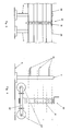
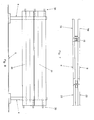
- the barrier transition for removably closing road gaps which has been generally indicated by the reference number 1, comprises longitudinal elements 20, made by coupling two barrier sections, and connected to one another by a hinge assembly 30, the removable pin 31 of which constitutes a disengagement element for opening the road gap. at one or more points.
- each element 20 is supported on the ground by two supporting feet 4 which can freely slide on the ground 5.
- said transition barrier can optionally comprise, either fully or partially, a lifting and sliding system 60, arranged near the feet 4 and comprising an adjustable lifting device 61, so designed as to turn about a vertical axis passing through a hub 62, and further including one or more wheels 63 for only contacting the ground as the road gap is opened.
- the terminal or end elements 8 are conventionally bolted to an existing fixed barrier 90, which can be either metal barrier 91 or a concrete barrier 92.
- terminal elements 8 are suitably modified at their end portions for coupling to a strong ground driven pole 10.
- the end portion of the barrier terminal can be constructed, by any prior method, so as to absorb impacts.
- a barrier transition has been provided which is designed to absorb angled impacts from vehicles, meeting, for example, the European standard EN 1317, and which can be essentially dynamically deformed so as to guide an impacting vehicle to its carriageway again.
- the barrier has a stiffened construction and operates in an elastic range, in order to achieve small side dynamic deformation (camber), 'thereby increasing the safety level of the transition.
- connection with respect to the fixed barrier is such as to provide a gradual deformation of the fixed barrier, thereby preventing any dangerous hard points from occurring.
- the existing barrier can be easily modified by only two maintenance operators who can use an optional service vehicle and related tooling.
- the same operators can disengage either one or more element connections, lower the optionally provided wheels, for facilitating the sliding thereof, and quickly open the system as a book either from a part or from the other, or from both parts.
- the corrugated panels are arranged from the ground at a maximum height of 600 to 1,200 mm and preferably from 800 to 1,100 mm.
- the panels can have any desired contour and moment of inertia, even with barriers of closed circular or polygonal cross-section.
- the longitudinal elements can be colored or decorated with patterns, to allow the closure region to be clearly seen.
- the used materials, as well as the contingent size and shapes can be any, depending on requirements.
Landscapes
- Engineering & Computer Science (AREA)
- Architecture (AREA)
- Civil Engineering (AREA)
- Structural Engineering (AREA)
- Refuge Islands, Traffic Blockers, Or Guard Fence (AREA)
- Road Paving Structures (AREA)
- Road Signs Or Road Markings (AREA)
Applications Claiming Priority (2)
| Application Number | Priority Date | Filing Date | Title |
|---|---|---|---|
| ITMI010521 | 2001-03-12 | ||
| IT2001MI000521A ITMI20010521A1 (it) | 2001-03-12 | 2001-03-12 | Transizione tra barriere di sicurezza per la chiusura facilmente amovibile |
Publications (3)
| Publication Number | Publication Date |
|---|---|
| EP1247905A2 true EP1247905A2 (de) | 2002-10-09 |
| EP1247905A3 EP1247905A3 (de) | 2005-11-02 |
| EP1247905B1 EP1247905B1 (de) | 2011-02-16 |
Family
ID=11447239
Family Applications (1)
| Application Number | Title | Priority Date | Filing Date |
|---|---|---|---|
| EP02005619A Expired - Lifetime EP1247905B1 (de) | 2001-03-12 | 2002-03-12 | Durchgang durch Leitplanken von Fahrbahnen |
Country Status (5)
| Country | Link |
|---|---|
| US (1) | US6712545B2 (de) |
| EP (1) | EP1247905B1 (de) |
| AT (1) | ATE498742T1 (de) |
| DE (1) | DE60239172D1 (de) |
| IT (1) | ITMI20010521A1 (de) |
Cited By (1)
| Publication number | Priority date | Publication date | Assignee | Title |
|---|---|---|---|---|
| US8647012B2 (en) | 2010-05-05 | 2014-02-11 | Energy Absorption Systems, Inc. | Gate for barrier system and methods for the assembly and use thereof |
Families Citing this family (11)
| Publication number | Priority date | Publication date | Assignee | Title |
|---|---|---|---|---|
| NL1020420C2 (nl) * | 2002-04-18 | 2003-10-21 | Laura Metaal Eygelshoven B V | Barrierelement. |
| US7104720B2 (en) * | 2003-11-19 | 2006-09-12 | Cyro Industries | Traffic noise barrier system |
| US7546900B2 (en) * | 2004-02-12 | 2009-06-16 | Evonik Cyro Llc | Panel assembly for traffic noise barrier wall |
| GB0503269D0 (en) * | 2005-02-17 | 2005-03-23 | Gerrard Marcus | Impact resisting post |
| US8206056B2 (en) | 2006-06-12 | 2012-06-26 | Patriot Barrier Systems, Llc | Barrier system |
| US7942602B2 (en) * | 2006-06-12 | 2011-05-17 | Protectus, Llc | Barrier system |
| US11198980B2 (en) * | 2017-12-18 | 2021-12-14 | Neusch Innovations, Lp | Passive anti-ram vehicle barrier |
| US12037756B2 (en) | 2015-04-22 | 2024-07-16 | Neusch Innovations, Lp | Post and beam vehicle barrier |
| CA2936510C (en) | 2016-07-19 | 2022-08-30 | Ben Powell | A transition barrier for connecting a permanent barrier to a temporary barrier |
| CN106710235A (zh) * | 2016-12-09 | 2017-05-24 | 河海大学 | 一种基于限载桥梁的车辆超重测试报警系统 |
| US10767325B2 (en) | 2018-01-05 | 2020-09-08 | Superior Transparent Noise Barriers LLC | Impact absorbing traffic noise barrier system |
Citations (1)
| Publication number | Priority date | Publication date | Assignee | Title |
|---|---|---|---|---|
| WO2000023658A1 (en) | 1998-10-16 | 2000-04-27 | Snoline S.P.A. | Improved removable barrier construction |
Family Cites Families (13)
| Publication number | Priority date | Publication date | Assignee | Title |
|---|---|---|---|---|
| FR2701499B1 (fr) * | 1993-02-12 | 1995-07-28 | Cofiroute | Element mobile et amovible de separateur de voies, permettant de creer une ouverture dans la rambarde situee entre les deux voies d'une autoroute, et notamment dans un muret en beton. |
| DE4333577A1 (de) * | 1993-10-01 | 1995-04-06 | Sps Schutzplanken Gmbh | Wiederverwendbare passive Schutzeinrichtung zum Aufsetzen auf Verkehrswege |
| IT1270041B (it) * | 1994-04-18 | 1997-04-28 | Snoline Spa | Struttura di barriera per la chiusura amovibile di varchi stradali |
| US5531540A (en) * | 1995-01-13 | 1996-07-02 | Yew Corporation | Reinforcement system for highway barriers |
| IT1281410B1 (it) * | 1995-08-11 | 1998-02-18 | Stori Leopoldo Gasparetto | Barriera metallica di sicurezza per by-pass stradali |
| FR2741093B1 (fr) * | 1995-11-14 | 1998-02-06 | Studia | Separateur continu mobile |
| US5685665A (en) * | 1996-05-09 | 1997-11-11 | Lembo; M. Carl | Roadway barrier and method of installation |
| US6293727B1 (en) * | 1997-06-05 | 2001-09-25 | Exodyne Technologies, Inc. | Energy absorbing system for fixed roadside hazards |
| US6059491A (en) * | 1997-11-14 | 2000-05-09 | Striefel; Richard R. | Portable barrier |
| SE513070C2 (sv) * | 1998-02-10 | 2000-07-03 | Gunnar Englund Byggare Ab | Skyddsbarriär avsedd att placeras mellan skilda körbanor hos en väg |
| US6164865A (en) * | 1998-09-14 | 2000-12-26 | Mccallum; Gerald L. | Interlocking barrier system with multiple securing mechanisms |
| FR2795106B1 (fr) * | 1999-06-18 | 2001-09-07 | Colas Sa | Dispositif d'interruption de terre-plein central |
| WO2003028111A1 (en) * | 2001-09-25 | 2003-04-03 | Sony Corporation | Nonvolatile semiconductor memory device and its manufacturing method |
-
2001
- 2001-03-12 IT IT2001MI000521A patent/ITMI20010521A1/it unknown
-
2002
- 2002-03-11 US US10/095,798 patent/US6712545B2/en not_active Expired - Lifetime
- 2002-03-12 DE DE60239172T patent/DE60239172D1/de not_active Expired - Lifetime
- 2002-03-12 EP EP02005619A patent/EP1247905B1/de not_active Expired - Lifetime
- 2002-03-12 AT AT02005619T patent/ATE498742T1/de not_active IP Right Cessation
Patent Citations (1)
| Publication number | Priority date | Publication date | Assignee | Title |
|---|---|---|---|---|
| WO2000023658A1 (en) | 1998-10-16 | 2000-04-27 | Snoline S.P.A. | Improved removable barrier construction |
Cited By (1)
| Publication number | Priority date | Publication date | Assignee | Title |
|---|---|---|---|---|
| US8647012B2 (en) | 2010-05-05 | 2014-02-11 | Energy Absorption Systems, Inc. | Gate for barrier system and methods for the assembly and use thereof |
Also Published As
| Publication number | Publication date |
|---|---|
| ATE498742T1 (de) | 2011-03-15 |
| US6712545B2 (en) | 2004-03-30 |
| EP1247905A3 (de) | 2005-11-02 |
| ITMI20010521A1 (it) | 2002-09-12 |
| US20020127056A1 (en) | 2002-09-12 |
| DE60239172D1 (de) | 2011-03-31 |
| EP1247905B1 (de) | 2011-02-16 |
Similar Documents
| Publication | Publication Date | Title |
|---|---|---|
| US5947452A (en) | Energy absorbing crash cushion | |
| US5547310A (en) | Barrier construction for removably closing road passages | |
| EP1247905B1 (de) | Durchgang durch Leitplanken von Fahrbahnen | |
| EP1540086B1 (de) | Aufgeweitetes Energieabsorptionssystem | |
| CA2583791C (en) | Combined guardrail and cable safety system | |
| US7059590B2 (en) | Impact assembly for an energy absorbing device | |
| US20070215849A1 (en) | Yielding post guardrail safety system incorporating thrie beam guardrail elements | |
| AU5562099A (en) | Energy absorbing system for fixed roadside hazards | |
| US20060193688A1 (en) | Flared Energy Absorbing System and Method | |
| AU764084B2 (en) | Improved removable barrier construction | |
| KR200293171Y1 (ko) | 레일감속장치를 이용한 충격흡수형 도로 안전시설물 | |
| US20070063178A1 (en) | Guardrail flange protector | |
| US20070063177A1 (en) | Yielding post guardrail safety system | |
| MXPA06006590A (es) | Sistema de seguridad de atenuacion de energia. | |
| CN214459938U (zh) | 一种公路用可防冲撞的公路护板 | |
| CN111364396B (zh) | 一种可移动高速公路隔离带 | |
| MXPA01004889A (en) | Improved removable barrier construction | |
| KR101213077B1 (ko) | 굴절연결식 저형고 이동형 배리어 | |
| KR20120116894A (ko) | 굴절연결식 저형고 이동형 배리어 | |
| WO2007035694A2 (en) | Yielding post guardrail safety system | |
| DE20005907U1 (de) | Selbstbremsender Sicherungsanhänger als Schutzschild für Arbeitstrupps auf Schnellstrassen etc. |
Legal Events
| Date | Code | Title | Description |
|---|---|---|---|
| PUAI | Public reference made under article 153(3) epc to a published international application that has entered the european phase |
Free format text: ORIGINAL CODE: 0009012 |
|
| AK | Designated contracting states |
Kind code of ref document: A2 Designated state(s): AT BE CH CY DE DK ES FI FR GB GR IE IT LI LU MC NL PT SE TR |
|
| AX | Request for extension of the european patent |
Free format text: AL;LT;LV;MK;RO;SI |
|
| PUAL | Search report despatched |
Free format text: ORIGINAL CODE: 0009013 |
|
| AK | Designated contracting states |
Kind code of ref document: A3 Designated state(s): AT BE CH CY DE DK ES FI FR GB GR IE IT LI LU MC NL PT SE TR |
|
| AX | Request for extension of the european patent |
Extension state: AL LT LV MK RO SI |
|
| RIC1 | Information provided on ipc code assigned before grant |
Ipc: 7E 01F 15/12 A Ipc: 7E 01F 15/00 B |
|
| 17P | Request for examination filed |
Effective date: 20060125 |
|
| AKX | Designation fees paid |
Designated state(s): AT BE CH CY DE DK ES FI FR GB GR IE IT LI LU MC NL PT SE TR |
|
| GRAP | Despatch of communication of intention to grant a patent |
Free format text: ORIGINAL CODE: EPIDOSNIGR1 |
|
| GRAS | Grant fee paid |
Free format text: ORIGINAL CODE: EPIDOSNIGR3 |
|
| GRAA | (expected) grant |
Free format text: ORIGINAL CODE: 0009210 |
|
| AK | Designated contracting states |
Kind code of ref document: B1 Designated state(s): AT BE CH CY DE DK ES FI FR GB GR IE IT LI LU MC NL PT SE TR |
|
| REG | Reference to a national code |
Ref country code: GB Ref legal event code: FG4D |
|
| REG | Reference to a national code |
Ref country code: CH Ref legal event code: EP |
|
| REG | Reference to a national code |
Ref country code: IE Ref legal event code: FG4D |
|
| REF | Corresponds to: |
Ref document number: 60239172 Country of ref document: DE Date of ref document: 20110331 Kind code of ref document: P |
|
| REG | Reference to a national code |
Ref country code: DE Ref legal event code: R096 Ref document number: 60239172 Country of ref document: DE Effective date: 20110331 |
|
| PGFP | Annual fee paid to national office [announced via postgrant information from national office to epo] |
Ref country code: IE Payment date: 20110329 Year of fee payment: 10 |
|
| REG | Reference to a national code |
Ref country code: NL Ref legal event code: VDEP Effective date: 20110216 |
|
| PG25 | Lapsed in a contracting state [announced via postgrant information from national office to epo] |
Ref country code: GR Free format text: LAPSE BECAUSE OF FAILURE TO SUBMIT A TRANSLATION OF THE DESCRIPTION OR TO PAY THE FEE WITHIN THE PRESCRIBED TIME-LIMIT Effective date: 20110517 Ref country code: PT Free format text: LAPSE BECAUSE OF FAILURE TO SUBMIT A TRANSLATION OF THE DESCRIPTION OR TO PAY THE FEE WITHIN THE PRESCRIBED TIME-LIMIT Effective date: 20110616 Ref country code: ES Free format text: LAPSE BECAUSE OF FAILURE TO SUBMIT A TRANSLATION OF THE DESCRIPTION OR TO PAY THE FEE WITHIN THE PRESCRIBED TIME-LIMIT Effective date: 20110527 Ref country code: SE Free format text: LAPSE BECAUSE OF FAILURE TO SUBMIT A TRANSLATION OF THE DESCRIPTION OR TO PAY THE FEE WITHIN THE PRESCRIBED TIME-LIMIT Effective date: 20110216 |
|
| PG25 | Lapsed in a contracting state [announced via postgrant information from national office to epo] |
Ref country code: AT Free format text: LAPSE BECAUSE OF FAILURE TO SUBMIT A TRANSLATION OF THE DESCRIPTION OR TO PAY THE FEE WITHIN THE PRESCRIBED TIME-LIMIT Effective date: 20110216 Ref country code: CY Free format text: LAPSE BECAUSE OF FAILURE TO SUBMIT A TRANSLATION OF THE DESCRIPTION OR TO PAY THE FEE WITHIN THE PRESCRIBED TIME-LIMIT Effective date: 20110216 Ref country code: NL Free format text: LAPSE BECAUSE OF FAILURE TO SUBMIT A TRANSLATION OF THE DESCRIPTION OR TO PAY THE FEE WITHIN THE PRESCRIBED TIME-LIMIT Effective date: 20110216 Ref country code: FI Free format text: LAPSE BECAUSE OF FAILURE TO SUBMIT A TRANSLATION OF THE DESCRIPTION OR TO PAY THE FEE WITHIN THE PRESCRIBED TIME-LIMIT Effective date: 20110216 Ref country code: BE Free format text: LAPSE BECAUSE OF FAILURE TO SUBMIT A TRANSLATION OF THE DESCRIPTION OR TO PAY THE FEE WITHIN THE PRESCRIBED TIME-LIMIT Effective date: 20110216 |
|
| PG25 | Lapsed in a contracting state [announced via postgrant information from national office to epo] |
Ref country code: MC Free format text: LAPSE BECAUSE OF NON-PAYMENT OF DUE FEES Effective date: 20110331 Ref country code: DK Free format text: LAPSE BECAUSE OF FAILURE TO SUBMIT A TRANSLATION OF THE DESCRIPTION OR TO PAY THE FEE WITHIN THE PRESCRIBED TIME-LIMIT Effective date: 20110216 |
|
| REG | Reference to a national code |
Ref country code: CH Ref legal event code: PL |
|
| PLBE | No opposition filed within time limit |
Free format text: ORIGINAL CODE: 0009261 |
|
| REG | Reference to a national code |
Ref country code: FR Ref legal event code: ST Effective date: 20111130 |
|
| STAA | Information on the status of an ep patent application or granted ep patent |
Free format text: STATUS: NO OPPOSITION FILED WITHIN TIME LIMIT |
|
| 26N | No opposition filed |
Effective date: 20111117 |
|
| PG25 | Lapsed in a contracting state [announced via postgrant information from national office to epo] |
Ref country code: DE Free format text: LAPSE BECAUSE OF NON-PAYMENT OF DUE FEES Effective date: 20111001 Ref country code: CH Free format text: LAPSE BECAUSE OF NON-PAYMENT OF DUE FEES Effective date: 20110331 Ref country code: LI Free format text: LAPSE BECAUSE OF NON-PAYMENT OF DUE FEES Effective date: 20110331 Ref country code: FR Free format text: LAPSE BECAUSE OF NON-PAYMENT OF DUE FEES Effective date: 20110418 |
|
| REG | Reference to a national code |
Ref country code: DE Ref legal event code: R119 Ref document number: 60239172 Country of ref document: DE Effective date: 20111001 |
|
| REG | Reference to a national code |
Ref country code: IE Ref legal event code: MM4A |
|
| PG25 | Lapsed in a contracting state [announced via postgrant information from national office to epo] |
Ref country code: IE Free format text: LAPSE BECAUSE OF NON-PAYMENT OF DUE FEES Effective date: 20120312 |
|
| PG25 | Lapsed in a contracting state [announced via postgrant information from national office to epo] |
Ref country code: LU Free format text: LAPSE BECAUSE OF NON-PAYMENT OF DUE FEES Effective date: 20110312 |
|
| PG25 | Lapsed in a contracting state [announced via postgrant information from national office to epo] |
Ref country code: TR Free format text: LAPSE BECAUSE OF FAILURE TO SUBMIT A TRANSLATION OF THE DESCRIPTION OR TO PAY THE FEE WITHIN THE PRESCRIBED TIME-LIMIT Effective date: 20110216 |
|
| PGFP | Annual fee paid to national office [announced via postgrant information from national office to epo] |
Ref country code: IT Payment date: 20210329 Year of fee payment: 20 |
|
| PGFP | Annual fee paid to national office [announced via postgrant information from national office to epo] |
Ref country code: GB Payment date: 20210329 Year of fee payment: 20 |
|
| REG | Reference to a national code |
Ref country code: GB Ref legal event code: PE20 Expiry date: 20220311 |
|
| PG25 | Lapsed in a contracting state [announced via postgrant information from national office to epo] |
Ref country code: GB Free format text: LAPSE BECAUSE OF EXPIRATION OF PROTECTION Effective date: 20220311 |