EP1247983A1 - Pompe à piston pour systèmes hydrauliques - Google Patents
Pompe à piston pour systèmes hydrauliques Download PDFInfo
- Publication number
- EP1247983A1 EP1247983A1 EP01108795A EP01108795A EP1247983A1 EP 1247983 A1 EP1247983 A1 EP 1247983A1 EP 01108795 A EP01108795 A EP 01108795A EP 01108795 A EP01108795 A EP 01108795A EP 1247983 A1 EP1247983 A1 EP 1247983A1
- Authority
- EP
- European Patent Office
- Prior art keywords
- piston
- pump
- pressure
- pressure control
- check valve
- Prior art date
- Legal status (The legal status is an assumption and is not a legal conclusion. Google has not performed a legal analysis and makes no representation as to the accuracy of the status listed.)
- Granted
Links
- 238000002485 combustion reaction Methods 0.000 claims abstract description 12
- 239000000314 lubricant Substances 0.000 claims description 16
- 239000007788 liquid Substances 0.000 claims description 7
- 239000012530 fluid Substances 0.000 abstract description 10
- 239000010687 lubricating oil Substances 0.000 abstract 1
- 230000000717 retained effect Effects 0.000 abstract 1
- 230000006835 compression Effects 0.000 description 6
- 238000007906 compression Methods 0.000 description 6
- 238000006073 displacement reaction Methods 0.000 description 3
- 239000000446 fuel Substances 0.000 description 1
- 238000009434 installation Methods 0.000 description 1
- 239000000463 material Substances 0.000 description 1
- 230000010363 phase shift Effects 0.000 description 1
Images
Classifications
-
- F—MECHANICAL ENGINEERING; LIGHTING; HEATING; WEAPONS; BLASTING
- F04—POSITIVE - DISPLACEMENT MACHINES FOR LIQUIDS; PUMPS FOR LIQUIDS OR ELASTIC FLUIDS
- F04B—POSITIVE-DISPLACEMENT MACHINES FOR LIQUIDS; PUMPS
- F04B49/00—Control, e.g. of pump delivery, or pump pressure of, or safety measures for, machines, pumps, or pumping installations, not otherwise provided for, or of interest apart from, groups F04B1/00 - F04B47/00
- F04B49/16—Control, e.g. of pump delivery, or pump pressure of, or safety measures for, machines, pumps, or pumping installations, not otherwise provided for, or of interest apart from, groups F04B1/00 - F04B47/00 by adjusting the capacity of dead spaces of working chambers
Definitions
- the invention relates to a piston pump containing one Delivery piston, a pressure relief piston, a return spring, one Pressure control spring and two check valves, preferably suitable for this sufficient hydraulic pressure to operate a variable To ensure valve control in reciprocating internal combustion engines.
- a variable valve control for reciprocating internal combustion engines is known from EP 1 046 793.
- the existing lubricant pump Lubricant flow generated is used at the end of the camshaft adjustment device located between the drive wheel and the camshaft actuate, which in turn causes a phase shift of the camshaft.
- the adjustment devices mentioned are usually supplied by Bores in the camshaft, with the control of the lubricant flow generally done by solenoid valves.
- This known device has the disadvantage that at low Speeds of the reciprocating piston internal combustion engine, the amount of lubricant sufficient, but the lubricant pressure is usually too low to Actuating devices or the actuation is too slow.
- This known disadvantage has so far been compensated for by the fact that a Lubricant pump with increased delivery capacity is installed. This leads to however, very high power consumption of the pump at higher speeds the reciprocating internal combustion engine, which is undesirable, however, because it is the Efficiency reduced.
- two-stage or variable pumps used which has sufficient lubricant pressure at low speeds ensure, however, a not so high power consumption at high Have speeds. However, these pumps are very expensive.
- a pump of the type mentioned at the outset is known from EP 0 976 926. she serves a liquid medium such. B. to promote fuel and / or pressure to increase.
- a cam drives one directly or by means of a push rod Piston on, which can move up and down in a cylindrical bore.
- the piston moves upwards, the fluid flows through the Output channel off while simultaneously through a liquid check valve reaches the second side of the piston.
- the downward movement of the piston lets the liquid through while the first check valve closes flow a second check valve into the cylinder.
- a disadvantage of the type of pump described is that it is often very high Liquid pressures can be achieved in the above application are also a hindrance.
- the object of the present invention is a Booster pump to improve so that it is approximately constant fluid pressure for the supply of the Guaranteed camshaft adjustment devices and at the same time the Disadvantages of the known solutions, high costs or high Power consumption, avoids, with a small footprint.
- the cylinder head of a reciprocating piston internal combustion engine contains at least one Camshaft provided with a known camshaft adjusting device is.
- the cylinder head contains a Housing in which the individual parts of the booster pump are housed are.
- This housing can be an integral part of the cylinder head or can be fitted as a separate part.
- Transfer piston in a known manner directly or by means of a plunger already existing cams of the engine valve control or advantageous from an additional cam located on the camshaft is driven.
- the transfer piston is designed as a hollow part with a fluid drainage and transverse at the cam end Pressure compensation hole. The transfer piston is closed on the cam side and abuts the camshaft while the opposite end is open.
- the open end of the transfer piston is closed by the Pressure control piston against the pressure control piston spring a circlip embedded in a groove in the transfer piston is pressed.
- Other components of the pump are also a compression spring, which in known way leads the transfer piston non-positively on the cam and one or two check valves. This opens in an advantageous way Design of the pressure spring held check valve during the Suction strokes to the inlet duct integrated into the housing during this second check valve on the side when the desired one is reached Delivery pressure releases liquid into the pressure channel.
- An advantageous embodiment of the present invention is that all parts belonging to the booster pump pre-assembled in one insert be, so that a simple assembly of the pump is possible.
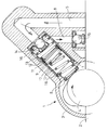
- the housing 3 contains a fluid inlet channel 5, which in a known manner during the operation of a reciprocating piston internal combustion engine with lubricant is acted upon, a fluid drainage channel or delivery channel 6 and one Bore 7, the individual parts of the booster pump or a sleeve 17th (containing the booster pump shown here).
- a transfer piston 8 is in the bore 7 or, as shown here, in the sleeve 17 mounted displaceably, with a likewise in the transfer piston 8 displaceably mounted pressure control piston 9 and a Pressure control spring 10, both held by a locking ring 11, arranged are.
- the pressure control spring 10, shown here, can also be any other type from the energy store that fulfills the function.
- the transfer piston 8 is in turn by a disc 12 by a second Compression spring 13 pressed against the cam of the camshaft 4, so that a constant frictional contact between the transfer piston and cam is guaranteed.
- the spring strength of the compression spring should be as small as possible to keep the required drive power for the pump low.
- the compression spring 13 also holds a check valve 14 in position.
- the check valve 14 serves the lubricant in one Displacement 16 let in while the check valve 15 as Exhaust valve is provided.
- the Transfer piston 8 (containing the pressure control spring 10 and Pressure control piston 9 secured by the circlip 11), the disc 12, the Compression spring 13 and the inlet check valve 14 mounted in a sleeve 17 and secured by a second locking ring 18, the sleeve 17 on the Camshaft side for receiving the transfer piston 8 is open and on the Lubricant inlet side a sufficiently large bore to fill the Pump through the inlet check valve 14 has.
- the outlet pressure should have a certain desired value do not exceed. This value is determined by the stiffness of the pressure control spring and the area of the pressure control piston. Now becomes the one you want Output pressure reached during the cam stroke, the Pressure control spring compressed and no further pressure increase takes place instead of.
- the desired pressure for the Camshaft adjustment device may still be on additional pressure relief valve (not shown here) either in inlet channel 5 or to be provided in the delivery channel 6.
- the invention thus shows a device for increasing the pressure in fluids which low material consumption and extremely low installation effort in almost all common housing of the type mentioned above can be brought in to the Pressure supply to the camshaft adjustment device as required increase.
Landscapes
- Engineering & Computer Science (AREA)
- Mechanical Engineering (AREA)
- General Engineering & Computer Science (AREA)
- Valve Device For Special Equipments (AREA)
- Lubrication Of Internal Combustion Engines (AREA)
- Details Of Reciprocating Pumps (AREA)
- Reciprocating Pumps (AREA)
- Fuel-Injection Apparatus (AREA)
Priority Applications (3)
| Application Number | Priority Date | Filing Date | Title |
|---|---|---|---|
| DE50108826T DE50108826D1 (de) | 2001-04-07 | 2001-04-07 | Kolbenpumpe für Hydrauliksysteme |
| EP01108795A EP1247983B1 (fr) | 2001-04-07 | 2001-04-07 | Pompe à piston pour systèmes hydrauliques |
| US10/063,169 US6676389B2 (en) | 2001-04-07 | 2002-03-27 | Piston pump for increasing pressure, comprising a transfer piston and a pressure-control piston |
Applications Claiming Priority (1)
| Application Number | Priority Date | Filing Date | Title |
|---|---|---|---|
| EP01108795A EP1247983B1 (fr) | 2001-04-07 | 2001-04-07 | Pompe à piston pour systèmes hydrauliques |
Publications (2)
| Publication Number | Publication Date |
|---|---|
| EP1247983A1 true EP1247983A1 (fr) | 2002-10-09 |
| EP1247983B1 EP1247983B1 (fr) | 2006-02-01 |
Family
ID=8177088
Family Applications (1)
| Application Number | Title | Priority Date | Filing Date |
|---|---|---|---|
| EP01108795A Expired - Lifetime EP1247983B1 (fr) | 2001-04-07 | 2001-04-07 | Pompe à piston pour systèmes hydrauliques |
Country Status (3)
| Country | Link |
|---|---|
| US (1) | US6676389B2 (fr) |
| EP (1) | EP1247983B1 (fr) |
| DE (1) | DE50108826D1 (fr) |
Cited By (1)
| Publication number | Priority date | Publication date | Assignee | Title |
|---|---|---|---|---|
| DE10354599A1 (de) * | 2003-11-21 | 2005-06-16 | Zf Friedrichshafen Ag | Radialkolbenpumpe |
Families Citing this family (6)
| Publication number | Priority date | Publication date | Assignee | Title |
|---|---|---|---|---|
| US7314353B2 (en) * | 2004-10-08 | 2008-01-01 | Urschel Laboratories, Inc. | Pump assembly for transporting a cooling fluid |
| US20090272366A1 (en) * | 2008-04-30 | 2009-11-05 | Caterpillar Inc. | Internal combustion engine set up method and fuel pump having installation assist mechanism |
| DE102010041310A1 (de) * | 2010-09-24 | 2012-03-29 | Robert Bosch Gmbh | Pumpe und Verfahren zu deren Herstellung |
| DE102013016030A1 (de) * | 2013-09-26 | 2015-03-26 | Hydac System Gmbh | Fördereinrichtung |
| US11033943B2 (en) * | 2017-09-13 | 2021-06-15 | Ford Motor Company | Mechanical applicator for use in stamping die process to apply thermo-chromatic ink to aluminum heat treated panels |
| GB2622016B (en) * | 2022-08-30 | 2025-04-02 | Phinia Delphi Luxembourg Sarl | Lubricant dosing device for gaseous fuel engine |
Citations (3)
| Publication number | Priority date | Publication date | Assignee | Title |
|---|---|---|---|---|
| FR2157546A5 (fr) * | 1971-10-18 | 1973-06-01 | Kloeckner Humboldt Deutz Ag | |
| FR2210722A1 (fr) * | 1973-11-26 | 1974-07-12 | Poclain Sa | |
| DE19820902A1 (de) * | 1998-05-09 | 1999-11-11 | Bosch Gmbh Robert | Kolbenpumpe |
Family Cites Families (6)
| Publication number | Priority date | Publication date | Assignee | Title |
|---|---|---|---|---|
| USRE28880E (en) * | 1967-07-21 | 1976-06-29 | Colorflo Limited | Printing machines feed mechanism |
| EP1046793A3 (fr) | 1999-04-21 | 2002-08-21 | Ford Global Technologies, Inc. | Dispositif de calage de soupape variable et méthode |
| DE19918122A1 (de) * | 1999-04-22 | 2000-11-23 | Bosch Gmbh Robert | Kolbenpumpe |
| JP3850598B2 (ja) * | 1999-10-07 | 2006-11-29 | 株式会社日立製作所 | 内燃機関のベーン式バルブタイミング制御装置 |
| US20020056427A1 (en) * | 1999-12-21 | 2002-05-16 | Chun Liang Lee | Cam timing system |
| JP4203703B2 (ja) * | 2000-06-14 | 2009-01-07 | アイシン精機株式会社 | 弁開閉時期制御装置 |
-
2001
- 2001-04-07 EP EP01108795A patent/EP1247983B1/fr not_active Expired - Lifetime
- 2001-04-07 DE DE50108826T patent/DE50108826D1/de not_active Expired - Lifetime
-
2002
- 2002-03-27 US US10/063,169 patent/US6676389B2/en not_active Expired - Lifetime
Patent Citations (3)
| Publication number | Priority date | Publication date | Assignee | Title |
|---|---|---|---|---|
| FR2157546A5 (fr) * | 1971-10-18 | 1973-06-01 | Kloeckner Humboldt Deutz Ag | |
| FR2210722A1 (fr) * | 1973-11-26 | 1974-07-12 | Poclain Sa | |
| DE19820902A1 (de) * | 1998-05-09 | 1999-11-11 | Bosch Gmbh Robert | Kolbenpumpe |
Cited By (1)
| Publication number | Priority date | Publication date | Assignee | Title |
|---|---|---|---|---|
| DE10354599A1 (de) * | 2003-11-21 | 2005-06-16 | Zf Friedrichshafen Ag | Radialkolbenpumpe |
Also Published As
| Publication number | Publication date |
|---|---|
| EP1247983B1 (fr) | 2006-02-01 |
| DE50108826D1 (de) | 2006-04-13 |
| US6676389B2 (en) | 2004-01-13 |
| US20020146337A1 (en) | 2002-10-10 |
Similar Documents
| Publication | Publication Date | Title |
|---|---|---|
| DE69909985T2 (de) | Hydraulisch betätigtes system mit verdrängerpumpe mit veränderlicher durchflussmenge und festem hub | |
| DE69929296T2 (de) | Hochdruckkraftstoffpumpe mit veränderlicher Druckflussmenge | |
| EP0927305B1 (fr) | Pompe a pistons | |
| DE10118754B4 (de) | Hochdruckpumpe | |
| DE19827926A1 (de) | Kraftstoffpumpe | |
| DE4126640A1 (de) | Pumpenanordnung mit pumpen-hauptstufe und vorgeschalteter vorfoerderpumpe | |
| DE60318363T2 (de) | Hydraulisches Ventilbetätigungssystem | |
| DE4138447C2 (de) | Motorbremse für eine mehrzylindrige Brennkraftmaschine | |
| WO2010055100A1 (fr) | Unité pompe pour une pompe à haute pression | |
| DE60301312T2 (de) | Treibstoffpumpenanordnung | |
| EP1247983B1 (fr) | Pompe à piston pour systèmes hydrauliques | |
| DE3048887A1 (de) | Steuerbarer ventiltrieb, insbesondere fuer die gaswechselventile einer hubkolben-brennkraftmaschine | |
| AT521256A4 (de) | Hydraulisches Steuerventil für eine längenverstellbare Pleuelstange mit geteilter Drainage | |
| WO1992008051A1 (fr) | Pompe a pistons, notamment pompe a pistons radiaux | |
| EP0609233A1 (fr) | Organe de reglage hydraulique. | |
| EP0757173A2 (fr) | Système d'injection de combustible | |
| AT521269B1 (de) | Hydraulisches Steuerventil für eine längenverstellbare Pleuelstange mit zwei Steuerdruckräumen | |
| DE2918867A1 (de) | Kraftstoffeinspritzpumpe fuer brennkraftmaschinen | |
| EP1798415B1 (fr) | Pompe à haute pression | |
| AT521159B1 (de) | Hydraulisches Steuerventil für eine längenverstellbare Pleuelstange mit einem stirnseitigen Steuerkolben | |
| AT521675B1 (de) | Hydraulisches Steuerventil für eine längenverstellbare Pleuelstange mit zwei stirnseitigen Steuerkolben | |
| DE4109472A1 (de) | Kraftstoffeinspritzpumpe | |
| WO1993013301A1 (fr) | Dispositif de commande hydraulique | |
| WO2007118535A1 (fr) | Commande de soupape | |
| AT521268B1 (de) | Längenverstellbare Pleuelstange mit hydraulischer Steuereinrichtung |
Legal Events
| Date | Code | Title | Description |
|---|---|---|---|
| PUAI | Public reference made under article 153(3) epc to a published international application that has entered the european phase |
Free format text: ORIGINAL CODE: 0009012 |
|
| AK | Designated contracting states |
Kind code of ref document: A1 Designated state(s): AT BE CH CY DE DK ES FI FR GB GR IE IT LI LU MC NL PT SE TR |
|
| AX | Request for extension of the european patent |
Free format text: AL;LT;LV;MK;RO;SI |
|
| 17P | Request for examination filed |
Effective date: 20030409 |
|
| AKX | Designation fees paid |
Designated state(s): DE FR GB |
|
| 17Q | First examination report despatched |
Effective date: 20040923 |
|
| RAP1 | Party data changed (applicant data changed or rights of an application transferred) |
Owner name: FORD GLOBAL TECHNOLOGIES, LLC |
|
| GRAP | Despatch of communication of intention to grant a patent |
Free format text: ORIGINAL CODE: EPIDOSNIGR1 |
|
| GRAS | Grant fee paid |
Free format text: ORIGINAL CODE: EPIDOSNIGR3 |
|
| GRAA | (expected) grant |
Free format text: ORIGINAL CODE: 0009210 |
|
| AK | Designated contracting states |
Kind code of ref document: B1 Designated state(s): DE FR GB |
|
| REG | Reference to a national code |
Ref country code: GB Ref legal event code: FG4D Free format text: NOT ENGLISH |
|
| REF | Corresponds to: |
Ref document number: 50108826 Country of ref document: DE Date of ref document: 20060413 Kind code of ref document: P |
|
| RAP2 | Party data changed (patent owner data changed or rights of a patent transferred) |
Owner name: FORD GLOBAL TECHNOLOGIES, LLC. |
|
| GBT | Gb: translation of ep patent filed (gb section 77(6)(a)/1977) |
Effective date: 20060719 |
|
| ET | Fr: translation filed | ||
| PLBE | No opposition filed within time limit |
Free format text: ORIGINAL CODE: 0009261 |
|
| STAA | Information on the status of an ep patent application or granted ep patent |
Free format text: STATUS: NO OPPOSITION FILED WITHIN TIME LIMIT |
|
| 26N | No opposition filed |
Effective date: 20061103 |
|
| REG | Reference to a national code |
Ref country code: FR Ref legal event code: PLFP Year of fee payment: 15 |
|
| PGFP | Annual fee paid to national office [announced via postgrant information from national office to epo] |
Ref country code: GB Payment date: 20150325 Year of fee payment: 15 |
|
| PGFP | Annual fee paid to national office [announced via postgrant information from national office to epo] |
Ref country code: DE Payment date: 20150429 Year of fee payment: 15 |
|
| PGFP | Annual fee paid to national office [announced via postgrant information from national office to epo] |
Ref country code: FR Payment date: 20150325 Year of fee payment: 15 |
|
| REG | Reference to a national code |
Ref country code: DE Ref legal event code: R119 Ref document number: 50108826 Country of ref document: DE |
|
| GBPC | Gb: european patent ceased through non-payment of renewal fee |
Effective date: 20160407 |
|
| REG | Reference to a national code |
Ref country code: FR Ref legal event code: ST Effective date: 20161230 |
|
| PG25 | Lapsed in a contracting state [announced via postgrant information from national office to epo] |
Ref country code: FR Free format text: LAPSE BECAUSE OF NON-PAYMENT OF DUE FEES Effective date: 20160502 Ref country code: GB Free format text: LAPSE BECAUSE OF NON-PAYMENT OF DUE FEES Effective date: 20160407 Ref country code: DE Free format text: LAPSE BECAUSE OF NON-PAYMENT OF DUE FEES Effective date: 20161101 |